DE102009055397A1 - Ceramic insulator for use in spark plug in direct injection engine, has UV-protection layer absorbing UV-radiation and comprising thickness that ranges from forty to sixty micrometers, where insulator is designed based on aluminum oxide - Google Patents
Ceramic insulator for use in spark plug in direct injection engine, has UV-protection layer absorbing UV-radiation and comprising thickness that ranges from forty to sixty micrometers, where insulator is designed based on aluminum oxide Download PDFInfo
- Publication number
- DE102009055397A1 DE102009055397A1 DE200910055397 DE102009055397A DE102009055397A1 DE 102009055397 A1 DE102009055397 A1 DE 102009055397A1 DE 200910055397 DE200910055397 DE 200910055397 DE 102009055397 A DE102009055397 A DE 102009055397A DE 102009055397 A1 DE102009055397 A1 DE 102009055397A1
- Authority
- DE
- Germany
- Prior art keywords
- insulator
- ceramic
- protective layer
- radiation
- spark plug
- Prior art date
- Legal status (The legal status is an assumption and is not a legal conclusion. Google has not performed a legal analysis and makes no representation as to the accuracy of the status listed.)
- Withdrawn
Links
Images
Classifications
-
- H—ELECTRICITY
- H01—ELECTRIC ELEMENTS
- H01T—SPARK GAPS; OVERVOLTAGE ARRESTERS USING SPARK GAPS; SPARKING PLUGS; CORONA DEVICES; GENERATING IONS TO BE INTRODUCED INTO NON-ENCLOSED GASES
- H01T13/00—Sparking plugs
- H01T13/20—Sparking plugs characterised by features of the electrodes or insulation
-
- C—CHEMISTRY; METALLURGY
- C04—CEMENTS; CONCRETE; ARTIFICIAL STONE; CERAMICS; REFRACTORIES
- C04B—LIME, MAGNESIA; SLAG; CEMENTS; COMPOSITIONS THEREOF, e.g. MORTARS, CONCRETE OR LIKE BUILDING MATERIALS; ARTIFICIAL STONE; CERAMICS; REFRACTORIES; TREATMENT OF NATURAL STONE
- C04B35/00—Shaped ceramic products characterised by their composition; Ceramics compositions; Processing powders of inorganic compounds preparatory to the manufacturing of ceramic products
- C04B35/01—Shaped ceramic products characterised by their composition; Ceramics compositions; Processing powders of inorganic compounds preparatory to the manufacturing of ceramic products based on oxide ceramics
- C04B35/10—Shaped ceramic products characterised by their composition; Ceramics compositions; Processing powders of inorganic compounds preparatory to the manufacturing of ceramic products based on oxide ceramics based on aluminium oxide
- C04B35/111—Fine ceramics
-
- C—CHEMISTRY; METALLURGY
- C04—CEMENTS; CONCRETE; ARTIFICIAL STONE; CERAMICS; REFRACTORIES
- C04B—LIME, MAGNESIA; SLAG; CEMENTS; COMPOSITIONS THEREOF, e.g. MORTARS, CONCRETE OR LIKE BUILDING MATERIALS; ARTIFICIAL STONE; CERAMICS; REFRACTORIES; TREATMENT OF NATURAL STONE
- C04B41/00—After-treatment of mortars, concrete, artificial stone or ceramics; Treatment of natural stone
- C04B41/009—After-treatment of mortars, concrete, artificial stone or ceramics; Treatment of natural stone characterised by the material treated
-
- C—CHEMISTRY; METALLURGY
- C04—CEMENTS; CONCRETE; ARTIFICIAL STONE; CERAMICS; REFRACTORIES
- C04B—LIME, MAGNESIA; SLAG; CEMENTS; COMPOSITIONS THEREOF, e.g. MORTARS, CONCRETE OR LIKE BUILDING MATERIALS; ARTIFICIAL STONE; CERAMICS; REFRACTORIES; TREATMENT OF NATURAL STONE
- C04B41/00—After-treatment of mortars, concrete, artificial stone or ceramics; Treatment of natural stone
- C04B41/45—Coating or impregnating, e.g. injection in masonry, partial coating of green or fired ceramics, organic coating compositions for adhering together two concrete elements
- C04B41/50—Coating or impregnating, e.g. injection in masonry, partial coating of green or fired ceramics, organic coating compositions for adhering together two concrete elements with inorganic materials
- C04B41/5025—Coating or impregnating, e.g. injection in masonry, partial coating of green or fired ceramics, organic coating compositions for adhering together two concrete elements with inorganic materials with ceramic materials
- C04B41/5041—Titanium oxide or titanates
-
- C—CHEMISTRY; METALLURGY
- C04—CEMENTS; CONCRETE; ARTIFICIAL STONE; CERAMICS; REFRACTORIES
- C04B—LIME, MAGNESIA; SLAG; CEMENTS; COMPOSITIONS THEREOF, e.g. MORTARS, CONCRETE OR LIKE BUILDING MATERIALS; ARTIFICIAL STONE; CERAMICS; REFRACTORIES; TREATMENT OF NATURAL STONE
- C04B41/00—After-treatment of mortars, concrete, artificial stone or ceramics; Treatment of natural stone
- C04B41/45—Coating or impregnating, e.g. injection in masonry, partial coating of green or fired ceramics, organic coating compositions for adhering together two concrete elements
- C04B41/50—Coating or impregnating, e.g. injection in masonry, partial coating of green or fired ceramics, organic coating compositions for adhering together two concrete elements with inorganic materials
- C04B41/5025—Coating or impregnating, e.g. injection in masonry, partial coating of green or fired ceramics, organic coating compositions for adhering together two concrete elements with inorganic materials with ceramic materials
- C04B41/5049—Zinc or bismuth oxides
-
- H—ELECTRICITY
- H01—ELECTRIC ELEMENTS
- H01B—CABLES; CONDUCTORS; INSULATORS; SELECTION OF MATERIALS FOR THEIR CONDUCTIVE, INSULATING OR DIELECTRIC PROPERTIES
- H01B3/00—Insulators or insulating bodies characterised by the insulating materials; Selection of materials for their insulating or dielectric properties
- H01B3/02—Insulators or insulating bodies characterised by the insulating materials; Selection of materials for their insulating or dielectric properties mainly consisting of inorganic substances
- H01B3/12—Insulators or insulating bodies characterised by the insulating materials; Selection of materials for their insulating or dielectric properties mainly consisting of inorganic substances ceramics
-
- H—ELECTRICITY
- H01—ELECTRIC ELEMENTS
- H01T—SPARK GAPS; OVERVOLTAGE ARRESTERS USING SPARK GAPS; SPARKING PLUGS; CORONA DEVICES; GENERATING IONS TO BE INTRODUCED INTO NON-ENCLOSED GASES
- H01T13/00—Sparking plugs
- H01T13/20—Sparking plugs characterised by features of the electrodes or insulation
- H01T13/38—Selection of materials for insulation
-
- H—ELECTRICITY
- H01—ELECTRIC ELEMENTS
- H01T—SPARK GAPS; OVERVOLTAGE ARRESTERS USING SPARK GAPS; SPARKING PLUGS; CORONA DEVICES; GENERATING IONS TO BE INTRODUCED INTO NON-ENCLOSED GASES
- H01T21/00—Apparatus or processes specially adapted for the manufacture or maintenance of spark gaps or sparking plugs
- H01T21/02—Apparatus or processes specially adapted for the manufacture or maintenance of spark gaps or sparking plugs of sparking plugs
-
- C—CHEMISTRY; METALLURGY
- C04—CEMENTS; CONCRETE; ARTIFICIAL STONE; CERAMICS; REFRACTORIES
- C04B—LIME, MAGNESIA; SLAG; CEMENTS; COMPOSITIONS THEREOF, e.g. MORTARS, CONCRETE OR LIKE BUILDING MATERIALS; ARTIFICIAL STONE; CERAMICS; REFRACTORIES; TREATMENT OF NATURAL STONE
- C04B2235/00—Aspects relating to ceramic starting mixtures or sintered ceramic products
- C04B2235/02—Composition of constituents of the starting material or of secondary phases of the final product
- C04B2235/30—Constituents and secondary phases not being of a fibrous nature
- C04B2235/32—Metal oxides, mixed metal oxides, or oxide-forming salts thereof, e.g. carbonates, nitrates, (oxy)hydroxides, chlorides
- C04B2235/3231—Refractory metal oxides, their mixed metal oxides, or oxide-forming salts thereof
- C04B2235/3232—Titanium oxides or titanates, e.g. rutile or anatase
-
- C—CHEMISTRY; METALLURGY
- C04—CEMENTS; CONCRETE; ARTIFICIAL STONE; CERAMICS; REFRACTORIES
- C04B—LIME, MAGNESIA; SLAG; CEMENTS; COMPOSITIONS THEREOF, e.g. MORTARS, CONCRETE OR LIKE BUILDING MATERIALS; ARTIFICIAL STONE; CERAMICS; REFRACTORIES; TREATMENT OF NATURAL STONE
- C04B2235/00—Aspects relating to ceramic starting mixtures or sintered ceramic products
- C04B2235/02—Composition of constituents of the starting material or of secondary phases of the final product
- C04B2235/30—Constituents and secondary phases not being of a fibrous nature
- C04B2235/32—Metal oxides, mixed metal oxides, or oxide-forming salts thereof, e.g. carbonates, nitrates, (oxy)hydroxides, chlorides
- C04B2235/3284—Zinc oxides, zincates, cadmium oxides, cadmiates, mercury oxides, mercurates or oxide forming salts thereof
-
- C—CHEMISTRY; METALLURGY
- C04—CEMENTS; CONCRETE; ARTIFICIAL STONE; CERAMICS; REFRACTORIES
- C04B—LIME, MAGNESIA; SLAG; CEMENTS; COMPOSITIONS THEREOF, e.g. MORTARS, CONCRETE OR LIKE BUILDING MATERIALS; ARTIFICIAL STONE; CERAMICS; REFRACTORIES; TREATMENT OF NATURAL STONE
- C04B2235/00—Aspects relating to ceramic starting mixtures or sintered ceramic products
- C04B2235/65—Aspects relating to heat treatments of ceramic bodies such as green ceramics or pre-sintered ceramics, e.g. burning, sintering or melting processes
- C04B2235/656—Aspects relating to heat treatments of ceramic bodies such as green ceramics or pre-sintered ceramics, e.g. burning, sintering or melting processes characterised by specific heating conditions during heat treatment
Abstract
Description
Stand der TechnikState of the art
Die vorliegende Erfindung betrifft einen keramischen Isolator, insbesondere basierend auf Aluminiumoxid, eine Zündkerze für eine Verbrennungskraftmaschine, umfassend den Isolator, und ein Verfahren zur Herstellung des Isolators.The present invention relates to a ceramic insulator, in particular based on alumina, a spark plug for an internal combustion engine, comprising the insulator, and a method for producing the insulator.
Der Stand der Technik kennt Keramiken, basierend auf Aluminiumoxid mit sehr guten isolierenden Eigenschaften und hoher Spannungsfestigkeit. Für den Einsatz solcher Isolatoren, beispielsweise in einer Zündkerze, wird Aluminiumoxid (Al2O3) mit Sinterhilfsmitteln versehen. Diese Sinterhilfsmittel setzen sich beispielsweise aus den drei Komponenten Magnesiumoxid (MgO), Kalziumoxid (CaO) und Siliziumoxid (SiO2) zusammen. Das Sinterhilfsmittel bildet eine schmelzflüssige Phase bei relativ niedrigen Temperaturen und verbessert dadurch die Sintereigenschaften des Materials.The prior art knows ceramics based on alumina with very good insulating properties and high dielectric strength. For the use of such insulators, for example in a spark plug, alumina (Al 2 O 3 ) is provided with sintering aids. These sintering aids are composed, for example, of the three components magnesium oxide (MgO), calcium oxide (CaO) and silicon oxide (SiO 2 ). The sintering aid forms a molten phase at relatively low temperatures, thereby improving the sintering properties of the material.
Offenbarung der ErfindungDisclosure of the invention
Der erfindungsgemäße keramische Isolator mit den Merkmalen gemäß Anspruch 1 weist eine deutlich verbesserte elektrische Durchschlagsfestigkeit auf. Insbesondere bei Anwendung des erfindungsgemäßen Isolators in einer Zündkerze ist es möglich, dass die Zündkerze kleiner konstruiert wird, wobei die Zündspannung unverändert verbleibt oder angehoben werden kann. Solche kleinbauenden Zündkerzen mit erhöhter Zündspannung finden insbesondere in modernen Verbrennungsmaschinen Anwendung, da hier beispielsweise bei direkt einspritzenden Motoren die Zündkerze sehr nahe an der Einspritzdüse platziert werden muss. Im Rahmen der Erfindung wurde festgestellt, dass im geschichteten Dielektrikum, d. h., bei einer Anordnung Elektrode/Luft/Keramik/Elektrode oder Elektrode/Luft/Keramik/Luft/Elektrode (wie sie in einer Zündkerze vorliegt), bei einem elektrischen Durchschlag in der Regel eine Teilentladung und unter Umständen auch ein Gleitfunke entsteht. Der Gleitfunke emittiert u. a. Strahlung im ultravioletten Bereich. Aluminiumoxid ist transparent für ultraviolette Strahlung. Dies bedeutet, dass die Strahlung in den Isolator vordringen kann und in den vorhandenen Poren das Gas ionisiert. Die geladenen Teilchen werden im elektrischen Feld zwischen den zwei Elektroden beschleunigt und können beim Auftreffen auf die Porenwandung die Kristallstruktur in der Keramik schädigen und folglich den elektrischen Durchbruch initiieren. Es wird dabei allgemein beobachtet, dass die Durchschlagsfestigkeit im geschichteten Dilektrikum wesentlich geringer ausfällt als im Falle einer Direktkontaktierung. Deshalb wird erfindungsgemäß der keramische Isolator vor der ionisierenden UV-Strahlung geschützt. Dadurch wird das Potential der Durchschlagsfestigkeit besser ausgenutzt und im besten Fall auf das Niveau der Direktkontaktierung angehoben. All diese Vorteile werden erreicht durch einen keramischen Isolator, insbesondere basierend auf Aluminiumoxid (Al2O3), umfassend ein zur Absorption von UV-Strahlung ausgebildetes Mittel, wobei das Mittel ein keramisches Material ist. Das keramische Material hat, z. B. gegenüber metallischen Schichten, den entscheidenden Vorteil, dass das keramische Material viel beständiger ist. Dies ist insbesondere bei der Verwendung des Isolators an einer Zündkerze bei den extremen Bedingungen eines Brennraumes von Interesse.The ceramic insulator according to the invention with the features according to
Die Unteransprüche zeigen bevorzugte Weiterbildungen der Erfindung.The dependent claims show preferred developments of the invention.
Vorteilhafterweise ist das Mittel zur Absorption von UV-Strahlung ein zur Absorption von UV-Strahlung ausgebildetes keramisches Additiv und/oder eine keramische UV-Schutzschicht. Das keramische Additiv im Isolatorbasismaterial bzw. die keramische UV-Schutzschicht absorbiert die UV-Strahlung, welche insbesondere durch die Gleitfunken entsteht.Advantageously, the means for absorbing UV radiation is a ceramic additive formed for absorbing UV radiation and / or a ceramic UV protective layer. The ceramic additive in the insulator base material or the ceramic UV protective layer absorbs the UV radiation, which is produced in particular by the sliding sparks.
Ferner ist vorteilhafterweise eine leitende Schutzschicht auf dem Isolator vorgesehen. Dadurch ist es möglich, dass die Teilentladung, welche vor dem elektrischen Durchschlag entsteht, zerstreut wird.Furthermore, a conductive protective layer is advantageously provided on the insulator. This makes it possible that the partial discharge, which arises before the electrical breakdown, is scattered.
Bevorzugt ist vorgesehen, dass das Additiv auf zumindest einem Teil der Oberfläche des Isolators konzentriert ist und somit die UV-Schutzschicht bildet. Diese UV-Schutzschicht absorbiert die UV-Strahlung noch bevor sie in das Innere des Isolators eindringen kann. Dadurch wird verhindert, dass Gas in den Poren des Isolators ionisiert wird und geladene Teilchen im elektrischen Feld beschleunigt werden.It is preferably provided that the additive is concentrated on at least part of the surface of the insulator and thus forms the UV protective layer. This UV protection layer absorbs the UV radiation even before it can penetrate into the interior of the insulator. This prevents gas from being ionized in the pores of the insulator and accelerating charged particles in the electric field.
In einer weiteren bevorzugten Ausgestaltung ist vorgesehen, dass das Additiv auf zumindest einem Teil der Oberfläche des Isolators konzentriert und/oder das Additiv im Isolator verteilt ist, um die UV-Transparenz des Isolators zu reduzieren. Bei der Herstellung des Isolators kann beispielsweise vor dem Sinterprozess das Basismaterial Aluminiumoxid mit dem Additiv in Pulverform vermischt werden. Nach einem Sinterprozess liegt dann das Additiv annähernd gleichmäßig verteilt im Isolator vor. Zusätzlich dazu oder alternativ wird das Additiv auf zumindest einem Teil der Oberfläche des Isolators konzentriert und bildet somit die oberflächliche UV-Schutzschicht.In a further preferred embodiment, it is provided that the additive is concentrated on at least part of the surface of the insulator and / or the additive is distributed in the insulator in order to reduce the UV transparency of the insulator. In the production of the insulator, for example, before the sintering process, the base material alumina can be mixed with the additive in powder form. After a sintering process, the additive is approximately evenly distributed in the insulator. Additionally or alternatively, the additive is concentrated on at least a portion of the surface of the insulator and thus forms the surface UV protective layer.
Ferner von Vorteil ist es, dass das Mittel zur Absorption der UV-Strahlung ein Metalloxid umfasst. Bevorzugterweise kommt hier Titanoxid (TiO2) und/oder Zinkoxid (ZnO) zur Anwendung. Diese beiden Materialien absorbieren wirkungsvoll die UV-Strahlung und können durch geeignete Dotierungen leitende Eigenschaften aufweisen. Darüber hinaus sind beide Oxide sehr stabil bei Brennraumbedingungen. Somit ist mit Titanoxid oder Zinkoxid jede der beschriebenen Möglichkeiten zur Erhöhung der elektrischen Durchschlagsfestigkeit des Isolators möglich. Erstens kann vor dem Sinterprozess das Oxid im Aluminiumoxid verteilt werden. Zweitens kann das Oxid auf zumindest einem Teil der Oberfläche des Isolators konzentriert werden und somit die UV-Schutzschicht bilden. Drittens kann das Oxid dotiert werden und somit die leitende Schutzschicht auf zumindest einem Teil der Oberfläche des Isolators bilden.It is also advantageous that the means for absorbing the UV radiation comprises a metal oxide. Preferably, titanium oxide (TiO 2 ) and / or zinc oxide (ZnO) is used here. These two materials effectively absorb the UV radiation and can be made by suitable doping have conductive properties. In addition, both oxides are very stable at combustion chamber conditions. Thus, any of the possibilities described for increasing the electrical breakdown strength of the insulator is possible with titanium oxide or zinc oxide. First, before the sintering process, the oxide can be distributed in the alumina. Second, the oxide can be concentrated on at least part of the surface of the insulator and thus form the UV protection layer. Third, the oxide may be doped and thus form the conductive protective layer on at least a portion of the surface of the insulator.
Vorteilhafterweise weist die leitende Schutzschicht und/oder die UV-Schutzschicht eine Schichtdicke von 1 μm bis 100 μm, insbesondere von 20 μm bis 80 μm, insbesondere von 40 μm bis 60 μm auf.Advantageously, the conductive protective layer and / or the UV protective layer has a layer thickness of 1 .mu.m to 100 .mu.m, in particular from 20 .mu.m to 80 .mu.m, in particular from 40 .mu.m to 60 .mu.m.
Bevorzugt ist ein Absorptionskoeffizient des keramischen Mittels zur Absorption von UV-Strahlung mindestens um den Faktor 1000, insbesondere um den Faktor 106, größer als der Absorptionskoeffizient von Aluminiumoxid (Al2O3). Somit ist bevorzugt ein Absorptionskoeffizient des Additivs mindestens um den Faktor 1000, insbesondere um den Faktor 106, größer als der Absorptionskoeffizient von Aluminiumoxid (Al2O3). Ferner bevorzugt ist ein Absorptionskoeffizient des Materials der UV-Schutzschicht mindestens um den Faktor 1000, insbesondere um den Faktor 106, größer als der Absorptionskoeffizient von Aluminiumoxid (Al2O3). Vorteilhafterweise ist die UV-Schutzschicht so ausgebildet, dass mindestens 90%, insbesondere mindestens 99%, der UV-Strahlung absorbiert werden.Preferably, an absorption coefficient of the ceramic agent for absorbing UV radiation is at least a factor of 1000, in particular by a factor of 10 6 , greater than the absorption coefficient of aluminum oxide (Al 2 O 3 ). Thus, an absorption coefficient of the additive is at least a factor of 1000, in particular by a factor of 10 6 , greater than the absorption coefficient of aluminum oxide (Al 2 O 3 ). Furthermore, an absorption coefficient of the material of the UV protective layer is at least a factor of 1000, in particular by a factor of 10 6 , greater than the absorption coefficient of aluminum oxide (Al 2 O 3 ). Advantageously, the UV protective layer is formed so that at least 90%, in particular at least 99%, of the UV radiation are absorbed.
Die Erfindung umfasst des Weiteren eine Zündkerze für eine Verbrennungskraftmaschine, umfassend einen soeben beschriebenen Isolator. Dabei wird bevorzugt in einem Bereich einer dielektrischen Schichtung von Elektrode/Luft/Isolator/Elektrode oder Elektrode/Luft/Isolator/Luft/Elektrode die keramische UV-Schutzschicht am Luft/Isolator-Übergang ausgebildet. Dadurch ist es möglich, noch kleinere Zündkerzen zu konstruieren, wobei die Zündspannung unverändert bleiben kann oder sogar angehoben werden kann. Dies ermöglicht die Verkleinerung moderner Verbrennungskraftmaschinen und insbesondere die sehr nahe Anordnung der Zündkerze an beispielsweise einer Einspritzung.The invention further comprises a spark plug for an internal combustion engine comprising an insulator just described. In this case, the ceramic UV protective layer at the air / insulator transition is preferably formed in a region of a dielectric stratification of electrode / air / insulator / electrode or electrode / air / insulator / air / electrode. This makes it possible to construct even smaller spark plugs, wherein the ignition voltage can remain unchanged or even can be raised. This allows the reduction of modern internal combustion engines and in particular the very close arrangement of the spark plug, for example, an injection.
In bevorzugter Ausbildung der Zündkerze ist vorgesehen, dass in einem sich zum Brennraum öffnenden Spalt zwischen dem Isolator und einem Gehäuse der Zündkerze, eine leitende Schutzschicht und die UV-Schutzschicht am Isolator ausgebildet sind. Vorteilhafterweise ist dabei die UV-Schutzschicht brennraumnäher als die leitende Schutzschicht ausgebildet. Beide Schutzschichten sind bevorzugt ringförmig über den kompletten Außenumfang des Isolators ausgebildet.In a preferred embodiment of the spark plug it is provided that in a gap opening between the insulator and a housing of the spark plug, a conductive protective layer and the UV protective layer are formed on the insulator. Advantageously, the UV protective layer is closer to the combustion chamber than the conductive protective layer. Both protective layers are preferably formed annular over the entire outer circumference of the insulator.
Des Weiteren umfasst die Erfindung ein Verfahren zur Herstellung eines keramischen Isolators, basierend auf Aluminiumoxid (Al2O3), wobei eine UV-Schutzschicht aus Keramik, insbesondere aus Titanoxid (TiO2), auf zumindest einem Teil der Oberfläche des Isolators zusammen mit der Basis aus Aluminiumoxid (Al2O3) gesintert wird. Aufgrund der vorteilhaften Eigenschaften von Titanoxid kann die Schutzschicht aus diesem Oxid direkt mit dem Seriensinterprozess des Aluminiumoxides eingebrannt werden. Dabei bildet sich an einer Grenzfläche zwischen der Schicht aus Titanoxid und dem Aluminiumoxid eine Reaktionszone aus. Die im Rahmen des erfindungsgemäßen keramischen Isolators beschriebenen Ausgestaltungen finden selbstverständlich auch im Rahmen des erfindungsgemäßen Verfahrens zur Herstellung des Isolators mit Titanoxid vorteilhafte Anwendung. Bevorzugt wird zwischen 1480°C und 1680°C, insbesondere zwischen 1560°C und 1600°C, gesintert.Furthermore, the invention comprises a method for producing a ceramic insulator based on aluminum oxide (Al 2 O 3 ), wherein a UV protective layer of ceramic, in particular of titanium oxide (TiO 2 ), on at least a part of the surface of the insulator together with the Base of alumina (Al 2 O 3 ) is sintered. Due to the advantageous properties of titanium oxide, the protective layer of this oxide can be baked directly with the series sintering process of the aluminum oxide. In this case, a reaction zone is formed at an interface between the layer of titanium oxide and the aluminum oxide. The embodiments described in the context of the ceramic insulator according to the invention are of course also in the context of the inventive method for producing the insulator with titanium oxide advantageous application. Preference is given between 1480 ° C and 1680 ° C, in particular between 1560 ° C and 1600 ° C, sintered.
Ferner umfasst die Erfindung ein Verfahren zur Herstellung eines keramischen Isolators, basieren auf Aluminiumoxid (Al2O3), wobei zuerst die Basis aus Aluminiumoxid (Al2O3) gesintert wird und anschließend eine UV-Schutzschicht aus Zinkoxid (ZnO) auf zumindest einem Teil der Oberfläche des Isolators eingebrannt wird. Das Zinkoxid wird aufgrund seiner niedrigen Verdampfungstemperatur bevorzugt in einem zusätzlichen Brennvorgang mit einer Temperatur < 1300°C eingebrannt. Die im Zusammenhang mit dem erfindungsgemäßen keramischen Isolator beschriebenen vorteilhaften Ausgestaltungen finden auch entsprechend vorteilhafte Anwendung auf das Verfahren zur Herstellung des keramischen Isolators mit Zinkoxid. Bevorzugt wird die Basis aus Aluminiumoxid (Al2O3) zwischen 1530°C und 1730°C, insbesondere zwischen 1610°C und 1650°C, gesintert, und das Zinkoxid (ZnO) wird mit kleiner 1300°C eingebrannt.Furthermore, the invention comprises a method for producing a ceramic insulator, based on alumina (Al 2 O 3 ), wherein first the base of alumina (Al 2 O 3 ) is sintered and then a UV protective layer of zinc oxide (ZnO) on at least one Part of the surface of the insulator is burned. The zinc oxide is preferably burned in an additional firing operation with a temperature <1300 ° C due to its low evaporation temperature. The advantageous embodiments described in connection with the ceramic insulator according to the invention also find correspondingly advantageous application to the method for producing the ceramic insulator with zinc oxide. Preferably, the base of alumina (Al 2 O 3 ) between 1530 ° C and 1730 ° C, in particular between 1610 ° C and 1650 ° C, sintered, and the zinc oxide (ZnO) is baked at less than 1300 ° C.
In bevorzugter Ausführung umfasst der Anteil des Titanoxides am Aluminiumoxid 0,01 bis 2 wt-%, insbesondere 0,01 bis 1 wt-%, insbesondere 0,4 bis 0,8 wt-%. Vorteilhafterweise umfasst der Anteil des Zinkoxides am Aluminiumoxid 0,01 bis 2 wt-%, insbesondere 0,01 bis 1 wt-%, insbesondere 0,01 bis 0,5 wt-%.In a preferred embodiment, the proportion of titanium oxide on the aluminum oxide comprises 0.01 to 2 wt%, in particular 0.01 to 1 wt%, in particular 0.4 to 0.8 wt%. Advantageously, the proportion of zinc oxide on the alumina 0.01 to 2 wt%, in particular 0.01 to 1 wt%, in particular 0.01 to 0.5 wt%.
Gemäß einem weiteren alternativen Verfahren zur Herstellung wird Aluminiumoxid mit einem keramischen Additiv zur Absorption von UV-Strahlung vermischt und dann der keramische Isolator hergestellt. Dieses Gemisch aus Aluminiumoxid und keramischen Additiv kann auch als Basismaterial für die beiden oben beschriebenen Verfahren verwendet werden.According to another alternative method of preparation, alumina is mixed with a ceramic additive to absorb UV radiation and then the ceramic insulator is made. This mixture of alumina and ceramic additive can also be used as a base material for the two methods described above.
Kurze Beschreibung der ZeichnungShort description of the drawing
Nachfolgend wird ein Ausführungsbeispiel der Erfindung unter Bezugnahme auf die begleitende Zeichnung im Detail beschrieben. In der Zeichnung zeigen:Hereinafter, an embodiment of the invention will be described in detail with reference to the accompanying drawings. In the drawing show:
Ausführungsform der ErfindungEmbodiment of the invention
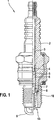
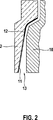
An der brennraumnahen Seite der Zündkerze
Anhand dieses Ausführungsbeispiels wurde gezeigt, wo die keramische UV-Schutzschicht
Claims (11)
Priority Applications (3)
| Application Number | Priority Date | Filing Date | Title |
|---|---|---|---|
| DE200910055397 DE102009055397A1 (en) | 2009-12-30 | 2009-12-30 | Ceramic insulator for use in spark plug in direct injection engine, has UV-protection layer absorbing UV-radiation and comprising thickness that ranges from forty to sixty micrometers, where insulator is designed based on aluminum oxide |
| JP2010290336A JP2011138771A (en) | 2009-12-30 | 2010-12-27 | Ceramic insulator, especially, ceramic insulator using aluminum oxide as base, and its manufacturing method |
| CN201010621982.8A CN102185256B (en) | 2009-12-30 | 2010-12-29 | Especially based on ceramics insulator and the manufacture method thereof of aluminum oxide |
Applications Claiming Priority (1)
| Application Number | Priority Date | Filing Date | Title |
|---|---|---|---|
| DE200910055397 DE102009055397A1 (en) | 2009-12-30 | 2009-12-30 | Ceramic insulator for use in spark plug in direct injection engine, has UV-protection layer absorbing UV-radiation and comprising thickness that ranges from forty to sixty micrometers, where insulator is designed based on aluminum oxide |
Publications (1)
| Publication Number | Publication Date |
|---|---|
| DE102009055397A1 true DE102009055397A1 (en) | 2011-07-07 |
Family
ID=44312465
Family Applications (1)
| Application Number | Title | Priority Date | Filing Date |
|---|---|---|---|
| DE200910055397 Withdrawn DE102009055397A1 (en) | 2009-12-30 | 2009-12-30 | Ceramic insulator for use in spark plug in direct injection engine, has UV-protection layer absorbing UV-radiation and comprising thickness that ranges from forty to sixty micrometers, where insulator is designed based on aluminum oxide |
Country Status (3)
| Country | Link |
|---|---|
| JP (1) | JP2011138771A (en) |
| CN (1) | CN102185256B (en) |
| DE (1) | DE102009055397A1 (en) |
Cited By (3)
| Publication number | Priority date | Publication date | Assignee | Title |
|---|---|---|---|---|
| WO2014131705A1 (en) * | 2013-03-01 | 2014-09-04 | Robert Bosch Gmbh | Spark plug |
| WO2016123310A1 (en) | 2015-01-29 | 2016-08-04 | Fram Group IP, LLC | Spark plug insulator having an anti-fouling coating and methods for minimizing fouling |
| US10707653B2 (en) | 2018-10-11 | 2020-07-07 | Federal-Mogul Ignition Llc | Spark plug |
Families Citing this family (2)
| Publication number | Priority date | Publication date | Assignee | Title |
|---|---|---|---|---|
| JP6631201B2 (en) | 2014-12-08 | 2020-01-15 | 株式会社デンソー | Ignition device and method for producing superhydrophilic film used therein |
| CN107248698B (en) * | 2017-06-29 | 2019-01-01 | 宋天顺 | A kind of resistor type spark plug |
Family Cites Families (7)
| Publication number | Priority date | Publication date | Assignee | Title |
|---|---|---|---|---|
| JP2857639B2 (en) * | 1988-02-19 | 1999-02-17 | 日本特殊陶業株式会社 | High alumina insulator for spark plug |
| JP3447102B2 (en) * | 1994-03-17 | 2003-09-16 | 東燃ゼネラル石油株式会社 | Method for producing transparent UV-absorbing ceramic film |
| BR9904840A (en) * | 1998-02-27 | 2000-07-25 | Ngk Spark Plug Co | Spark plug, alumina insulator for spark plug and its manufacturing method |
| BR9902148A (en) * | 1998-05-22 | 1999-12-28 | Ngk Spark Plug Co | Spark plug and its manufacturing method. |
| JP2007042656A (en) * | 1998-05-22 | 2007-02-15 | Ngk Spark Plug Co Ltd | Spark plug and its manufacturing method |
| JP4474724B2 (en) * | 1999-05-24 | 2010-06-09 | 株式会社デンソー | Lead-free glaze and spark plug |
| DE102005062115A1 (en) * | 2005-12-23 | 2007-06-28 | Robert Bosch Gmbh | Glow, ignition or heating element for combustion and/or heating devices, especially glow plugs, spark plugs or heaters has highly stable corrosion protection layer comprising mixture of SiO2 and other material |
-
2009
- 2009-12-30 DE DE200910055397 patent/DE102009055397A1/en not_active Withdrawn
-
2010
- 2010-12-27 JP JP2010290336A patent/JP2011138771A/en active Pending
- 2010-12-29 CN CN201010621982.8A patent/CN102185256B/en not_active Expired - Fee Related
Cited By (5)
| Publication number | Priority date | Publication date | Assignee | Title |
|---|---|---|---|---|
| WO2014131705A1 (en) * | 2013-03-01 | 2014-09-04 | Robert Bosch Gmbh | Spark plug |
| US9819155B2 (en) | 2013-03-01 | 2017-11-14 | Robert Bosch Gmbh | Spark plug |
| WO2016123310A1 (en) | 2015-01-29 | 2016-08-04 | Fram Group IP, LLC | Spark plug insulator having an anti-fouling coating and methods for minimizing fouling |
| EP3251186A4 (en) * | 2015-01-29 | 2018-08-22 | FRAM Group IP LLC | Spark plug insulator having an anti-fouling coating and methods for minimizing fouling |
| US10707653B2 (en) | 2018-10-11 | 2020-07-07 | Federal-Mogul Ignition Llc | Spark plug |
Also Published As
| Publication number | Publication date |
|---|---|
| CN102185256A (en) | 2011-09-14 |
| JP2011138771A (en) | 2011-07-14 |
| CN102185256B (en) | 2015-11-25 |
Similar Documents
| Publication | Publication Date | Title |
|---|---|---|
| DE102014106313B4 (en) | Spark plug and spark plug insulator | |
| DE102009055397A1 (en) | Ceramic insulator for use in spark plug in direct injection engine, has UV-protection layer absorbing UV-radiation and comprising thickness that ranges from forty to sixty micrometers, where insulator is designed based on aluminum oxide | |
| DE102018115386B4 (en) | spark plug | |
| DE3616668A1 (en) | SPARK PLUG WITH GLIDING RANGE | |
| DE2520787A1 (en) | SPARK PLUG WITH BUILT-IN RESISTOR | |
| DE2854071A1 (en) | SPARK PLUG ISOLATOR | |
| DE102019126626A1 (en) | spark plug | |
| DE102015112014B4 (en) | Alumina sintered body and spark plug | |
| EP3192138A1 (en) | Ceramic spark plug insulator, spark plug, and use of a glaze on a spark plug insulator | |
| DE10349077A1 (en) | Cylinder head and spark plug | |
| DE102018210480B4 (en) | spark plug | |
| EP1875570A1 (en) | Electrode for a spark plug | |
| EP1053579A1 (en) | Spark plug for an internal combustion engine | |
| DE102013226667B4 (en) | Spark plug with seal made of a non-conductive material | |
| DE3149676A1 (en) | IGNITION DEVICE | |
| EP1544457A1 (en) | Device for igniting an air-fuel mixture in a combustion engine | |
| EP2118973B1 (en) | Spark plug and insulator composed of high-purity aluminium oxide ceramic | |
| DE102022124348A1 (en) | SPARK PLUG AND METHOD OF PRODUCTION | |
| WO1987001876A1 (en) | Spark plug with surface discharge section | |
| DE102014110432A1 (en) | Method for igniting a fuel-air mixture, ignition system and glow plug | |
| WO1997010632A1 (en) | Sparking plug and process for its production | |
| DE10360191A1 (en) | Ignition apparatus for air-fuel mixture in internal combustion engine, has ignition pin which partially consists rotationally symmetric outside partial pin and inside partial pin having electroconductivity higher than outside partial pin | |
| DE2109415C3 (en) | High voltage spark plugs and processes for their manufacture | |
| DE102007053807A1 (en) | Heater plug for starting self-igniting internal combustion engine, has glow plug including shell that is manufactured from ceramic material, and core made of material with dielectric strength of twenty kilovolt/millimeter | |
| DE102018117212A1 (en) | Spark plug with polymer sealing ring |
Legal Events
| Date | Code | Title | Description |
|---|---|---|---|
| R012 | Request for examination validly filed | ||
| R119 | Application deemed withdrawn, or ip right lapsed, due to non-payment of renewal fee |