DE102008063243A1 - Device for manufacturing thin layer solar cell modules, particularly for manufacturing longitudinal contacting, comprises working head and longitudinal contacting which is arranged on substrate, where working head and substrate are moved - Google Patents
Device for manufacturing thin layer solar cell modules, particularly for manufacturing longitudinal contacting, comprises working head and longitudinal contacting which is arranged on substrate, where working head and substrate are moved Download PDFInfo
- Publication number
- DE102008063243A1 DE102008063243A1 DE102008063243A DE102008063243A DE102008063243A1 DE 102008063243 A1 DE102008063243 A1 DE 102008063243A1 DE 102008063243 A DE102008063243 A DE 102008063243A DE 102008063243 A DE102008063243 A DE 102008063243A DE 102008063243 A1 DE102008063243 A1 DE 102008063243A1
- Authority
- DE
- Germany
- Prior art keywords
- substrate
- working head
- dispensing
- adhesive
- applying
- Prior art date
- Legal status (The legal status is an assumption and is not a legal conclusion. Google has not performed a legal analysis and makes no representation as to the accuracy of the status listed.)
- Ceased
Links
Classifications
-
- H—ELECTRICITY
- H10—SEMICONDUCTOR DEVICES; ELECTRIC SOLID-STATE DEVICES NOT OTHERWISE PROVIDED FOR
- H10F—INORGANIC SEMICONDUCTOR DEVICES SENSITIVE TO INFRARED RADIATION, LIGHT, ELECTROMAGNETIC RADIATION OF SHORTER WAVELENGTH OR CORPUSCULAR RADIATION
- H10F71/00—Manufacture or treatment of devices covered by this subclass
- H10F71/137—Batch treatment of the devices
- H10F71/1375—Apparatus for automatic interconnection of photovoltaic cells in a module
-
- Y—GENERAL TAGGING OF NEW TECHNOLOGICAL DEVELOPMENTS; GENERAL TAGGING OF CROSS-SECTIONAL TECHNOLOGIES SPANNING OVER SEVERAL SECTIONS OF THE IPC; TECHNICAL SUBJECTS COVERED BY FORMER USPC CROSS-REFERENCE ART COLLECTIONS [XRACs] AND DIGESTS
- Y02—TECHNOLOGIES OR APPLICATIONS FOR MITIGATION OR ADAPTATION AGAINST CLIMATE CHANGE
- Y02E—REDUCTION OF GREENHOUSE GAS [GHG] EMISSIONS, RELATED TO ENERGY GENERATION, TRANSMISSION OR DISTRIBUTION
- Y02E10/00—Energy generation through renewable energy sources
- Y02E10/50—Photovoltaic [PV] energy
Landscapes
- Coating Apparatus (AREA)
Abstract
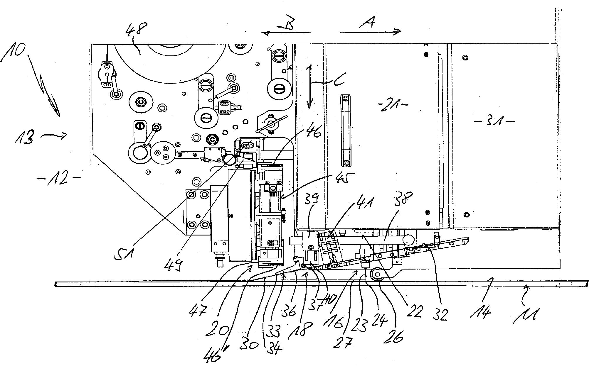
Eine Einrichtung (10) zur Herstellung der Längskontaktierung der auf einem Substrat (11) angeordneten und elektrisch in Reihe zu verschaltenden Dünnschicht-Solarzellen, ist mit einem Arbeitskopf (13) versehen, wobei Substrat (11) und/oder Arbeitskopf (13) verfahrbar sind bzw. ist. Eine derartige Einrichtung soll in platzsparender Weise aufgebaut sein und zeitreduzierte Arbeitsschritte ermöglichen. Hierzu ist vorgesehen, dass der Arbeitskopf (13) sowohl mit einer Vorrichtung (16) zum Abgeben und Auftragen eines Klebers als auch mit einer Vorrichtung (18) zum Abgeben und Aufbringen eines metallischen Bandes (30) sowie mit einer Vorrichtung (20) zum Spenden und Aufdrücken von Klebepads (46) versehen ist.A device (10) for producing the longitudinal contact of the thin-film solar cells arranged on a substrate (11) and electrically connected in series is provided with a working head (13), wherein substrate (11) and / or working head (13) are movable or is. Such a device should be constructed in a space-saving manner and allow time-reduced steps. For this purpose, it is provided that the working head (13) both with a device (16) for dispensing and applying an adhesive as well as with a device (18) for dispensing and applying a metallic strip (30) and with a device (20) for dispensing and pressing adhesive pads (46) is provided.
Description
Die vorliegende Erfindung bezieht sich auf eine Einrichtung zum Herstellen von Dünnschicht-Solarzellen-Modulen nach dem Oberbegriff des Anspruchs 1.The The present invention relates to a device for manufacturing of thin-film solar cell modules according to the preamble of claim 1.
Die Herstellung eines Dünnschicht-Solarzellen-Moduls umfasst eine Vielzahl von Bearbeitungsschritten unter anderem bei der elektrischen Verschaltung. Hierzu sind bisher verschiedene Bearbeitungsstationen vorgesehen, die das Dünnschicht-Solarzellen-Modul nacheinander durchlaufen muss. Dies ist nicht zuletzt aufgrund der Wege zwischen den einzelnen Stationen relativ zeitaufwändig. Außerdem ist der Raumbedarf erheblich.The Production of a thin-film solar cell module includes a variety of processing steps among others the electrical connection. For this purpose, so far different processing stations provided the thin-film solar cell module must go through one after the other. This is not least because of Paths between the individual stations are relatively time-consuming. Besides that is the space requirement considerably.
Aufgabe der vorliegenden Erfindung ist es, eine Einrichtung zum Herstellen von Dünnschicht-Solarzellen-Modulen der eingangs genannten Art zu schaffen, die in platzsparender Weise aufgebaut ist und zeitreduzierte Arbeitsschritte ermöglicht.task It is the object of the present invention to provide a device for manufacturing of thin-film solar cell modules of the type mentioned above, in a space-saving manner is constructed and allows time-reduced steps.
Zur Lösung dieser Aufgabe sind bei einer Einrichtung zum Herstellen von Dünnschicht-Solarzellen-Modulen der eingangs genannten Art die im Anspruch 1 angegebenen Merkmale vorgesehen.to solution This object is achieved in a device for producing thin-film solar cell modules of the type mentioned in the features specified in claim 1 intended.
Durch die erfindungsgemäßen Maßnahmen ist es möglich, beispielsweise die Längskontaktierung der auf einem Substrat angeordneten und elektrisch in Reihe zu verschaltenden Dünnschicht-Solarzellen in einer einzigen Station vorzunehmen, was nicht nur in platzsparender sondern auch in zeiteinsparender Weise erfolgen kann. Mit Hilfe dieses Kombinationsarbeitskopfes ist es möglich, auf die Dünnschicht-Solarzellen sowohl die Kleberraupe als auch darauf das metallische Band als auch zur positionsgenauen Fixierung des metallischen Bandes auf dieses Klebepads aufzubringen, worauf das so präparierte Substrat einer Station zur Aushärtung des Klebers zugeführt wird.By the measures according to the invention it is possible for example, the longitudinal contact arranged on a substrate and electrically connected in series Thin film solar cells in a single station, not only in space-saving but can also be done in a time-saving manner. With help This combination working head, it is possible on the thin-film solar cells both the glue bead as well as on the metallic band as well Positionally accurate fixation of the metallic strip on this adhesive pads to apply what it was prepared for Substrate of a curing station supplied to the adhesive becomes.
In vorteilhafter Weise sind die Merkmale gemäß Anspruch 2 vorgesehen, was zu einer weiteren Zeiteinsparung führt.In Advantageously, the features are provided according to claim 2, which leads to a further time saving.
Vorteilhafte Ausgestaltungen der Vorrichtung zum Abgeben und Auftragen eines Klebers ergeben sich aus den Merkmalen des Anspruchs 3 und/oder denen des Anspruchs 4 sowie gegebenenfalls denen des Anspruchs 5.advantageous Embodiments of the device for dispensing and applying a Adhesives result from the features of claim 3 and / or those of claim 4 and optionally those of claim 5.
Mit den Merkmalen nach Anspruch 6 ist eine vorteilhafte Konstruktion der Vorrichtung zum Abgeben und Aufbringen eines metallischen Bandes erreicht. Dabei kann es zweckmäßig sein, die Merkmale nach Anspruch 7 und/oder diejenigen nach Anspruch 8 vorzusehen.With The features of claim 6 is an advantageous construction the device for dispensing and applying a metallic strip reached. It may be appropriate the features of claim 7 and / or those of claim 8 provided.
In vorteilhafter Weise ist die Vorrichtung zum Spenden und Aufdrücken von Klebepads mit den Merkmalen nach Anspruch ausgestattet.In Advantageously, the device for dispensing and pressing of Adhesive pads equipped with the features according to claim.
Zur zeitlich unmittelbar aufeinanderfolgenden abschnittsweisen Fixierung des metallischen Bandes mittels Klebepads sind die Merkmale nach Anspruch 10 vorgesehen.to temporally immediately consecutive section fixation the metallic band by means of adhesive pads are the features of claim 10 provided.
Eine weitere konstruktiv vorteilhafte Ausgestaltung der Vorrichtung zum Spenden und Aufdrücken von Klebepads ergibt sich aus den Merkmalen des Anspruchs 11.A Another structurally advantageous embodiment of the device for Donate and press of adhesive pads results from the features of claim 11.
Weitere Einzelheiten der Erfindung sind der folgenden Beschreibung zu entnehmen, in der die Erfindung anhand des in der Zeichnung dargestellten Ausführungsbeispieles näher beschrieben und erläutert ist.Further Details of the invention can be taken from the following description, in the invention with reference to the embodiment shown in the drawing described in more detail and explained is.
Die einzige Figur zeigt in schematischer Seitenansicht eine Einrichtung zur Herstellung der Längskontaktierung von auf einem Substrat angeordneten und elektrisch in Reihe zu verschaltenden Dünnschicht-Solarzellen gemäß einem bevorzugten Ausführungsbeispiel vorliegender Erfindung.The single figure shows a schematic side view of a device for producing the longitudinal contact of thin-film solar cells arranged on a substrate and to be electrically connected in series according to one preferred embodiment present invention.
Die
in der Zeichnung dargestellte Einrichtung
Der
Arbeitskopf
Die
Vorrichtung
In
Bewegungsrichtung A nachlaufend ist die Vorrichtung
In
Zuführrichtung
D des Bandes
In
Bewegungsrichtung A der Vorrichtung
Zunächst wird
mittels der Vorrichtung
Nach
auf diese Weise erfolgter Längskontaktierung
des Moduls in zwei Reihen, was entweder gleichzeitig durch parallele
Vorrichtungen oder nacheinander durch seitliches Verschieben des
Arbeitskopfes
Claims (11)
Priority Applications (1)
| Application Number | Priority Date | Filing Date | Title |
|---|---|---|---|
| DE102008063243A DE102008063243A1 (en) | 2008-12-16 | 2008-12-16 | Device for manufacturing thin layer solar cell modules, particularly for manufacturing longitudinal contacting, comprises working head and longitudinal contacting which is arranged on substrate, where working head and substrate are moved |
Applications Claiming Priority (1)
| Application Number | Priority Date | Filing Date | Title |
|---|---|---|---|
| DE102008063243A DE102008063243A1 (en) | 2008-12-16 | 2008-12-16 | Device for manufacturing thin layer solar cell modules, particularly for manufacturing longitudinal contacting, comprises working head and longitudinal contacting which is arranged on substrate, where working head and substrate are moved |
Publications (1)
| Publication Number | Publication Date |
|---|---|
| DE102008063243A1 true DE102008063243A1 (en) | 2010-07-01 |
Family
ID=42220766
Family Applications (1)
| Application Number | Title | Priority Date | Filing Date |
|---|---|---|---|
| DE102008063243A Ceased DE102008063243A1 (en) | 2008-12-16 | 2008-12-16 | Device for manufacturing thin layer solar cell modules, particularly for manufacturing longitudinal contacting, comprises working head and longitudinal contacting which is arranged on substrate, where working head and substrate are moved |
Country Status (1)
| Country | Link |
|---|---|
| DE (1) | DE102008063243A1 (en) |
Cited By (1)
| Publication number | Priority date | Publication date | Assignee | Title |
|---|---|---|---|---|
| WO2024079036A1 (en) * | 2022-10-13 | 2024-04-18 | M10 Solar Equipment GmbH | Method and device for applying adhesive to solar elements, method for producing solar modules and solar module manufacturing device |
Citations (1)
| Publication number | Priority date | Publication date | Assignee | Title |
|---|---|---|---|---|
| DE102007016386A1 (en) * | 2007-04-03 | 2008-10-09 | Aci-Ecotec Gmbh & Co.Kg | Photovoltaic cells contacting method, involves bonding insulating tape to cells, fixing metallic contact bands by adhesive tape pieces, where contact bands are electrically conductively connected with metal bands in contact positions |
-
2008
- 2008-12-16 DE DE102008063243A patent/DE102008063243A1/en not_active Ceased
Patent Citations (1)
| Publication number | Priority date | Publication date | Assignee | Title |
|---|---|---|---|---|
| DE102007016386A1 (en) * | 2007-04-03 | 2008-10-09 | Aci-Ecotec Gmbh & Co.Kg | Photovoltaic cells contacting method, involves bonding insulating tape to cells, fixing metallic contact bands by adhesive tape pieces, where contact bands are electrically conductively connected with metal bands in contact positions |
Cited By (1)
| Publication number | Priority date | Publication date | Assignee | Title |
|---|---|---|---|---|
| WO2024079036A1 (en) * | 2022-10-13 | 2024-04-18 | M10 Solar Equipment GmbH | Method and device for applying adhesive to solar elements, method for producing solar modules and solar module manufacturing device |
Similar Documents
| Publication | Publication Date | Title |
|---|---|---|
| DE102012108161A1 (en) | Method for joining metal strips | |
| EP2806986B1 (en) | Method and device for joining two metal strip ends | |
| DE102007016386A1 (en) | Photovoltaic cells contacting method, involves bonding insulating tape to cells, fixing metallic contact bands by adhesive tape pieces, where contact bands are electrically conductively connected with metal bands in contact positions | |
| EP0220415B1 (en) | Apparatus for cutting sheets | |
| EP1353420A1 (en) | Crimping device | |
| DE3781150T2 (en) | BROCHURE OR SIMILAR, METHOD AND DEVICE FOR PRODUCING THE SAME. | |
| DE2425101B2 (en) | Method and device for producing electrical contact elements | |
| EP2948382B1 (en) | Dispensing apparatus for dispensing a liquid on a substrate | |
| DE3224670C2 (en) | ||
| CH447001A (en) | Device for closing containers by means of a cover film | |
| DE2128767A1 (en) | Tool for straightening metal strips and for shaping elements | |
| DE102008063243A1 (en) | Device for manufacturing thin layer solar cell modules, particularly for manufacturing longitudinal contacting, comprises working head and longitudinal contacting which is arranged on substrate, where working head and substrate are moved | |
| DE2048079C3 (en) | Method and device for cold welding (solid-state welding) of two workpieces | |
| DE3528642A1 (en) | METHOD AND ARRANGEMENT FOR IMPRESSING CHANNELS WITH A SMALL CROSS-SECTION INTO THE SURFACE OF A WORKPIECE | |
| WO2009000682A1 (en) | Device for pressing against semiconductor chips | |
| DE60212956T2 (en) | AUXILIARY DEVICE AND METHOD FOR APPLYING TAPE | |
| DE102011076900A1 (en) | Method for moving electrical conductive cell contact tapes to e.g. photovoltaic thin layer solar cell modules, involves cutting-off tapes in initial position of head unit, so that renewed release of tapes is carried-out over moving length | |
| DE2321316A1 (en) | GUIDE RAIL FOR A MOTOR CHAIN SAW AND METHOD FOR MANUFACTURING IT | |
| DE8005406U1 (en) | DEVICE FOR APPLYING A COLOR STRIP PATTERN | |
| DE10322628B4 (en) | Method for producing a suction surface on an intended for the SMD mounting technology electrical component, in particular a coil, and apparatus for performing the method | |
| DE102008062877A1 (en) | Method for applying and aligning metallic bands, particularly electrically connecting contact strip in photovoltaic thin film solar cell modules, involves releasing metallic band over certain initial length | |
| DE19756958A1 (en) | Device for gluing block backs | |
| DE2711482A1 (en) | PLATE FOR HEAT SEALING MACHINES OR THE SAME | |
| DE3406301A1 (en) | Process for producing a mattress blank and system for carrying out the process | |
| DE1511870C (en) | Device for transferring heat-seal labels, which are detachably arranged on a carrier tape, to objects |
Legal Events
| Date | Code | Title | Description |
|---|---|---|---|
| OM8 | Search report available as to paragraph 43 lit. 1 sentence 1 patent law | ||
| OP8 | Request for examination as to paragraph 44 patent law | ||
| R081 | Change of applicant/patentee |
Owner name: ACI ECOTEC GMBH, DE Free format text: FORMER OWNER: ACI-ECOTEC GMBH & CO. KG, 78658 ZIMMERN, DE Effective date: 20110513 Owner name: ACI ECOTEC GMBH, DE Free format text: FORMER OWNER: ACI ECO TEC GMBH, 78658 ZIMMERN, DE Effective date: 20110701 |
|
| R082 | Change of representative |
Representative=s name: DREISS PATENTANWAELTE PARTG MBB, DE Effective date: 20110701 Representative=s name: DREISS PATENTANWAELTE PARTNERSCHAFT, DE Effective date: 20110701 Representative=s name: DREISS PATENTANWAELTE, DE Effective date: 20110701 Representative=s name: DREISS PATENTANWAELTE, 70188 STUTTGART, DE |
|
| R082 | Change of representative |
Representative=s name: DREISS PATENTANWAELTE PARTG MBB, DE Representative=s name: DREISS PATENTANWAELTE PARTNERSCHAFT, DE Representative=s name: DREISS PATENTANWAELTE, DE Representative=s name: DREISS PATENTANWAELTE, 70188 STUTTGART, DE |
|
| R082 | Change of representative |
Representative=s name: DREISS PATENTANWAELTE PARTG MBB, DE Representative=s name: DREISS PATENTANWAELTE PARTNERSCHAFT, DE Representative=s name: DREISS PATENTANWAELTE, DE Representative=s name: DREISS PATENTANWAELTE, 70188 STUTTGART, DE |
|
| R002 | Refusal decision in examination/registration proceedings | ||
| R003 | Refusal decision now final |
Effective date: 20140103 |