DE102008009862B4 - Refrigerator with a arranged outside the refrigerator lighting device - Google Patents
Refrigerator with a arranged outside the refrigerator lighting device Download PDFInfo
- Publication number
- DE102008009862B4 DE102008009862B4 DE102008009862.0A DE102008009862A DE102008009862B4 DE 102008009862 B4 DE102008009862 B4 DE 102008009862B4 DE 102008009862 A DE102008009862 A DE 102008009862A DE 102008009862 B4 DE102008009862 B4 DE 102008009862B4
- Authority
- DE
- Germany
- Prior art keywords
- light
- prisms
- lighting device
- emitting diodes
- refrigerator
- Prior art date
- Legal status (The legal status is an assumption and is not a legal conclusion. Google has not performed a legal analysis and makes no representation as to the accuracy of the status listed.)
- Expired - Fee Related
Links
Images
Classifications
-
- F—MECHANICAL ENGINEERING; LIGHTING; HEATING; WEAPONS; BLASTING
- F25—REFRIGERATION OR COOLING; COMBINED HEATING AND REFRIGERATION SYSTEMS; HEAT PUMP SYSTEMS; MANUFACTURE OR STORAGE OF ICE; LIQUEFACTION SOLIDIFICATION OF GASES
- F25D—REFRIGERATORS; COLD ROOMS; ICE-BOXES; COOLING OR FREEZING APPARATUS NOT OTHERWISE PROVIDED FOR
- F25D27/00—Lighting arrangements
-
- F—MECHANICAL ENGINEERING; LIGHTING; HEATING; WEAPONS; BLASTING
- F21—LIGHTING
- F21V—FUNCTIONAL FEATURES OR DETAILS OF LIGHTING DEVICES OR SYSTEMS THEREOF; STRUCTURAL COMBINATIONS OF LIGHTING DEVICES WITH OTHER ARTICLES, NOT OTHERWISE PROVIDED FOR
- F21V5/00—Refractors for light sources
- F21V5/02—Refractors for light sources of prismatic shape
-
- F—MECHANICAL ENGINEERING; LIGHTING; HEATING; WEAPONS; BLASTING
- F21—LIGHTING
- F21W—INDEXING SCHEME ASSOCIATED WITH SUBCLASSES F21K, F21L, F21S and F21V, RELATING TO USES OR APPLICATIONS OF LIGHTING DEVICES OR SYSTEMS
- F21W2131/00—Use or application of lighting devices or systems not provided for in codes F21W2102/00-F21W2121/00
- F21W2131/30—Lighting for domestic or personal use
- F21W2131/305—Lighting for domestic or personal use for refrigerators
-
- F—MECHANICAL ENGINEERING; LIGHTING; HEATING; WEAPONS; BLASTING
- F21—LIGHTING
- F21Y—INDEXING SCHEME ASSOCIATED WITH SUBCLASSES F21K, F21L, F21S and F21V, RELATING TO THE FORM OR THE KIND OF THE LIGHT SOURCES OR OF THE COLOUR OF THE LIGHT EMITTED
- F21Y2115/00—Light-generating elements of semiconductor light sources
- F21Y2115/10—Light-emitting diodes [LED]
Landscapes
- Engineering & Computer Science (AREA)
- General Engineering & Computer Science (AREA)
- Chemical & Material Sciences (AREA)
- Combustion & Propulsion (AREA)
- Physics & Mathematics (AREA)
- Mechanical Engineering (AREA)
- Thermal Sciences (AREA)
- Devices That Are Associated With Refrigeration Equipment (AREA)
- Arrangement Of Elements, Cooling, Sealing, Or The Like Of Lighting Devices (AREA)
Abstract
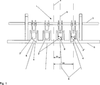
Kühlgerät mit einer außerhalb des Kühlraumes (10) angeordneten Beleuchtungseinrichtung (1), die im Bereich eines oberen horizontal ausgerichteten Wandabschnitts (12) des Kühlraumes (10) angeordnet ist wobei das von einer Lichtquelle ausgestrahlte Licht die Zugangsöffnung zum Kühlraum (10) und/oder ein ausgezogenes Schubfach (14) mit im wesentlichen vertikal nach unten gerichteten Lichtstrahlen (15) beleuchtet, dadurch gekennzeichnet, dass die Beleuchtungseinrichtung (1) eine Gruppe von nebeneinander angeordneten Leuchtdioden als Lichtquelle umfasst, denen in Abstrahlrichtung ein Lichtleitelement mit einer optischen Struktur zugeordnet ist, die derart ausgebildet ist, dass die Lichtstrahlung einen fächerartig nach unten erweiternden Strahlenverlauf bildet. wobei die Beleuchtungseinrichtung (1) mindestens eine erste Gruppe von Leuchtdioden (2') mit jeweils zugeordneten Prismen (4) umfasst, deren Lichteinkopplungsflächen (8) in einer gedachten Ebene liegen, die mit der Längsachse (9) der Prismen (4) einen Winkel α einschließen sowie mindestens eine zweite Gruppe von Leuchtdioden (2'') mit jeweils zugeordneten Prismen (4), deren Lichteinkopplungsflächen (8) unter einem vom Winkel α abweichenden Winkel β zur Längsachse (9) angeordnet sind, wobei die Lichteinkopplungsflächen (8) der Prismen (4) der ersten und zweiten Gruppe jeweils spiegelsymmetrisch zueinander angeordnet sind.Cooling device with an outside of the cooling chamber (10) arranged lighting device (1) which is arranged in the region of an upper horizontally oriented wall portion (12) of the cooling space (10) wherein the light emitted from a light source, the access opening to the cooling space (10) and / or an extended drawer (14) illuminated with substantially vertically downwardly directed light beams (15), characterized in that the illumination device (1) comprises a group of light emitting diodes arranged side by side as the light source, which is assigned in the emission direction, a light guide with an optical structure, which is formed such that the light radiation forms a fan-like downward expanding beam path. wherein the illumination device (1) comprises at least one first group of light-emitting diodes (2 ') each having associated prisms (4) whose light coupling surfaces (8) lie in an imaginary plane which forms an angle with the longitudinal axis (9) of the prisms (4) α and at least one second group of light-emitting diodes (2 '') each having associated prisms (4) whose light coupling surfaces (8) are arranged at an angle α different from the angle β to the longitudinal axis (9), wherein the light coupling surfaces (8) of Prisms (4) of the first and second group are each arranged in mirror symmetry to each other.
Description
Die Erfindung betrifft ein Kühlgerät mit einer außerhalb des Kühlraumes angeordneten Beleuchtungseinrichtung, die im Bereich eines oberen horizontal ausgerichteten Wandabschnitts des Kühlraumes angeordnet ist wobei das von einer Lichtquelle ausgestrahlte Licht die Zugangsöffnung zum Kühlraum und/oder ein ausgezogenes Schubfach mit im Wesentlichen vertikal nach unten gerichteten Lichtstrahlen beleuchtet und wobei die Beleuchtungseinrichtung eine Gruppe von Leuchtdioden umfasst, deren Lichtstrahlen einen fächerartig nach unten erweiterten Strahlenverlauf bildet.The invention relates to a cooling device with an illumination device arranged outside the cooling chamber, which is arranged in the region of an upper horizontally oriented wall section of the cooling space, wherein the light emitted by a light source is the access opening to the cooling space and / or an extended drawer with essentially vertically downward directed light rays illuminated and wherein the illumination device comprises a group of light-emitting diodes whose light beams forms a fan-like downwardly extended beam path.
Ein derartiges Kühlgerät ist beispielsweise aus der
Weiter ist aus der
Die Beleuchtungseinrichtung gemäß der
Ferner ist aus der
Aus der
Aus der
Eine derartige Beleuchtungseinrichtung ist aufgrund ihrer Geometrie nicht für den Einbau im Bereich der Bedienblende eines Kühlgerätes zur Ausleuchtung der Zugangsöffnung des Kühlraumes oder eines ausgezogenen Gefriergutauszugs geeingnet.Due to its geometry, such a lighting device is not suitable for installation in the area of the control panel of a refrigerator for illuminating the access opening of the cold room or a pulled-out frozen goods extension.
Der Erfindung stellt sich somit das Problem, ein Kühlgerät mit einer platzsparend außerhalb des Kühlraumes anzuordnenden Beleuchtungseinrichtung zu gestalten, mit der der Bereich der Zugangsöffnung und/oder ein Gefriergutauszug optimal beleuchtet werden kann.The invention thus raises the problem of designing a refrigerator with a space-saving to be arranged outside the refrigerator lighting device with which the area of the access opening and / or a frozen goods can be optimally illuminated.
Erfindungsgemäß wird dieses Problem durch ein Kühlgerät mit den Merkmalen des Patentanspruchs 1 gelöst. Vorteilhafte Ausgestaltungen und Weiterbildungen der Erfindung ergeben sich aus den nachfolgenden Unteransprüchen.According to the invention, this problem is solved by a cooling device having the features of
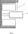
Die mit der Erfindung erreichbaren Vorteile bestehen neben der optimalen Beleuchtung/Ausleuchtung der Zugangsöffnung über annähernd die gesamte Kühlraumbreite bzw. Gefriergutauszugsbreite in der besonders platzsparenden Anordnung der Beleuchtungseinrichtung außerhalb des Kühlraumes vorzugsweise im Bereich der Steuer- und Bedieneinheit des Kühlgerätes. Als Lichtquelle kommen vorzugsweise LEDs zum Einsatz, die wartungsfrei und besonders platzsparend anzuordnen sind und eine geringe Wärmeentwicklung haben. Durch die Ausbildung der Beleuchtungseinrichtung mit einem Lichtleiteelement mit einer optischen Struktur kann die Lichtstrahlung einen fächerartig nach unten erweiterten Strahlenverlauf bilden. Vorzugsweise weist die Beleuchtungseinrichtung in einer Ausführungsform der Erfindung eine erste und eine zweite Gruppe von Leuchtdioden mit Lichtleitern auf, deren Lichteinkapplungsstellen unterschiedlich geneigte Flächen aufweisen, wodurch das Licht fächerartig über die Kühlraumbreite ausgestrahlt wird. Die Neigungswinkel der Lichteinstrittsflächen sind vorzugsweise unterschiedlich ausgebildet, so dass der Strahlenbereich der ersten Gruppe annähernd senkrecht ausgerichtete Lichtstrahlen erzeugt und der Strahlenbereich der zweiten Gruppe den seitlichen Randbereich der Kühlraumöffnung anstrahlt.The achievable with the present invention consist in addition to the optimal lighting / illumination of the access opening over approximately the entire refrigerator width or Gefriergutauszugsbreite in the particularly space-saving arrangement of the lighting device outside the refrigerator preferably in the control and operating unit of the refrigerator. The light source preferably LEDs are used, which are maintenance-free and particularly space-saving to arrange and have a low heat. By forming the illumination device with a light guiding element having an optical structure, the light radiation can fan out below form extended beam path. Preferably, in one embodiment of the invention, the illumination device comprises a first and a second group of light-emitting diodes with light guide surfaces having differently inclined surfaces, whereby the light is radiated fan-shaped over the cooling chamber width. The angles of inclination of the light entry surfaces are preferably designed differently, so that the radiation area of the first group generates approximately perpendicularly aligned light beams and the radiation area of the second group illuminates the lateral edge area of the cooling chamber opening.
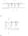
Bei der Erfindung sind die Lichteintrittsflächen der Lichtleiter einer Gruppe spiegelsymmetrisch zueinander angeordnet. Vorteilhaft weitergebildet sind sie in unterschiedlichen Abständen x1 und x2 zur Symmetrieachse der Beleuchtungseinrichtung angeordnet, wobei die Abstände x1 bzw. x2 die jeweilige Fächerbreite der Lichtstrahlung bestimmt.In the invention, the light entry surfaces of the light guides of a group are arranged mirror-symmetrically to one another. Advantageously developed they are arranged at different distances x1 and x2 to the axis of symmetry of the illumination device, wherein the distances x1 and x2 determines the respective fan width of the light radiation.
In einem zweiten Ausführungsbeispiel der Erfindung weist die Beleuchtungseinrichtung eine Streuscheibe mit einer Vielzahl nebeneinander angeordneter Prismen unterschiedlicher Neigungswinkel auf, wodurch die Lichtstrahlung ebenfalls fächerartig nach unten aufweitend über die Kühlraumbreite abgelenkt wird.In a second embodiment of the invention, the illumination device has a diffusing screen with a multiplicity of adjacently arranged prisms of different angles of inclination, as a result of which the light radiation is likewise deflected in a fan-like manner downward widening over the cooling chamber width.
In einer weiteren vorteilhaften Ausbildung der Erfindung sind mindestens zwei Beleuchtungseinrichtungen auf Abstand zueinander im Bereich des oberen horizontal ausgerichteten Wandabschnitts des Kühlraumes angeordnet. Die Beleuchtungseinrichtungen sind symmetrisch zueinander angeordnet, wodurch die Zugangsöffnung noch homogener beleuchtet wird. Ein weiterer vorteilhafter Lichteffekt wird durch Überlagerung der fächerförmigen Strahlen der beiden Beleuchtungseinrichtungen erreicht.In a further advantageous embodiment of the invention, at least two lighting devices are arranged at a distance from each other in the region of the upper horizontally oriented wall portion of the cooling space. The lighting devices are arranged symmetrically to each other, whereby the access opening is illuminated even more homogeneous. Another advantageous light effect is achieved by superposition of the fan-shaped beams of the two lighting devices.
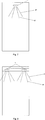
Ein Ausführungsbeispiel der Erfindung ist in den Zeichnungen rein schematisch dargestellt und wird nachfolgend näher beschrieben. Es zeigtAn embodiment of the invention is shown purely schematically in the drawings and will be described in more detail below. It shows
In der
Claims (5)
Priority Applications (3)
| Application Number | Priority Date | Filing Date | Title |
|---|---|---|---|
| DE102008009862.0A DE102008009862B4 (en) | 2008-02-19 | 2008-02-19 | Refrigerator with a arranged outside the refrigerator lighting device |
| PCT/EP2009/001013 WO2009103458A2 (en) | 2008-02-19 | 2009-02-13 | Cooling device having a lighting device disposed outside the cooling chamber |
| EP09713366A EP2255138A2 (en) | 2008-02-19 | 2009-02-13 | Cooling device having a lighting device disposed outside the cooling chamber |
Applications Claiming Priority (1)
| Application Number | Priority Date | Filing Date | Title |
|---|---|---|---|
| DE102008009862.0A DE102008009862B4 (en) | 2008-02-19 | 2008-02-19 | Refrigerator with a arranged outside the refrigerator lighting device |
Publications (2)
| Publication Number | Publication Date |
|---|---|
| DE102008009862A1 DE102008009862A1 (en) | 2009-09-10 |
| DE102008009862B4 true DE102008009862B4 (en) | 2015-12-17 |
Family
ID=40935995
Family Applications (1)
| Application Number | Title | Priority Date | Filing Date |
|---|---|---|---|
| DE102008009862.0A Expired - Fee Related DE102008009862B4 (en) | 2008-02-19 | 2008-02-19 | Refrigerator with a arranged outside the refrigerator lighting device |
Country Status (3)
| Country | Link |
|---|---|
| EP (1) | EP2255138A2 (en) |
| DE (1) | DE102008009862B4 (en) |
| WO (1) | WO2009103458A2 (en) |
Families Citing this family (6)
| Publication number | Priority date | Publication date | Assignee | Title |
|---|---|---|---|---|
| AT509563B1 (en) * | 2010-03-01 | 2015-10-15 | Hierzer Andreas | LIGHT WITH LIGHTING ELEMENTS |
| EP2394557B1 (en) * | 2010-03-18 | 2013-05-08 | Miele & Cie. KG | Dishwasher with a lighting system |
| EP2587201B1 (en) * | 2010-06-28 | 2017-03-08 | Hefei Midea Rongshida Refrigerator Co., Ltd. | Lighting device for drawer type refrigerator |
| DE102015004825A1 (en) * | 2014-12-30 | 2016-06-30 | Liebherr-Hausgeräte Lienz Gmbh | Fridge and / or freezer |
| DE102017130793A1 (en) * | 2017-11-20 | 2019-05-23 | Liebherr-Hausgeräte Ochsenhausen GmbH | Fridge and / or freezer |
| ES2961137T3 (en) * | 2020-02-21 | 2024-03-08 | Liebherr Hausgeraete Ochsenhausen Gmbh | Refrigerator and/or freezer with special lighting of the interior space |
Citations (9)
| Publication number | Priority date | Publication date | Assignee | Title |
|---|---|---|---|---|
| DE3238152C1 (en) * | 1982-10-14 | 1986-12-04 | Bosch-Siemens Hausgeräte GmbH, 7000 Stuttgart | Refrigerator, in particular fridge or freezer |
| DE29715157U1 (en) * | 1997-08-23 | 1998-01-15 | Fischer, Fritz-Udo, 56244 Ötzingen | Infrared-free and ultraviolet-free, white light diffusely radiating work lamp |
| DE69515293T2 (en) * | 1994-03-16 | 2000-09-21 | Itab Industri Ab, Joenkoeping | LIGHTING DEVICE |
| DE20204102U1 (en) * | 2002-03-13 | 2002-07-04 | Patent-Treuhand-Gesellschaft für elektrische Glühlampen mbH, 81543 München | Luminaire with light guide and multiple light sources |
| DE69715312T2 (en) * | 1996-06-14 | 2003-04-17 | Aktiebolaget Electrolux, Stockholm | Fridge or freezer with lighting system |
| DE10210161B4 (en) * | 2002-03-07 | 2004-01-08 | Miele & Cie. Kg | Beverage maker, especially coffee maker |
| EP1617133A2 (en) * | 2004-07-16 | 2006-01-18 | Osram Sylvania Inc. | Light emitting diode disc optic with heat sink housing |
| DE202005011279U1 (en) * | 2005-05-04 | 2006-09-07 | Liebherr-Hausgeräte Ochsenhausen GmbH | Fridge/freezer appliance for lighting a freezer space has an appliance carcass with cooling and refrigerating chambers and fridge/freezer doors for sealing the freezer space |
| WO2008087028A2 (en) * | 2007-01-19 | 2008-07-24 | Liebherr-Hausgeräte Ochsenhausen GmbH | Refrigerator and/or freezer |
Family Cites Families (3)
| Publication number | Priority date | Publication date | Assignee | Title |
|---|---|---|---|---|
| SE511216C2 (en) * | 1997-12-30 | 1999-08-23 | Itab Neon Ab | Lighting device with LEDs |
| TW457732B (en) * | 1999-08-27 | 2001-10-01 | Lumileds Lighting Bv | Luminaire, optical element and method of illuminating an object |
| JP4360945B2 (en) * | 2004-03-10 | 2009-11-11 | シチズン電子株式会社 | Lighting device |
-
2008
- 2008-02-19 DE DE102008009862.0A patent/DE102008009862B4/en not_active Expired - Fee Related
-
2009
- 2009-02-13 WO PCT/EP2009/001013 patent/WO2009103458A2/en not_active Ceased
- 2009-02-13 EP EP09713366A patent/EP2255138A2/en not_active Withdrawn
Patent Citations (9)
| Publication number | Priority date | Publication date | Assignee | Title |
|---|---|---|---|---|
| DE3238152C1 (en) * | 1982-10-14 | 1986-12-04 | Bosch-Siemens Hausgeräte GmbH, 7000 Stuttgart | Refrigerator, in particular fridge or freezer |
| DE69515293T2 (en) * | 1994-03-16 | 2000-09-21 | Itab Industri Ab, Joenkoeping | LIGHTING DEVICE |
| DE69715312T2 (en) * | 1996-06-14 | 2003-04-17 | Aktiebolaget Electrolux, Stockholm | Fridge or freezer with lighting system |
| DE29715157U1 (en) * | 1997-08-23 | 1998-01-15 | Fischer, Fritz-Udo, 56244 Ötzingen | Infrared-free and ultraviolet-free, white light diffusely radiating work lamp |
| DE10210161B4 (en) * | 2002-03-07 | 2004-01-08 | Miele & Cie. Kg | Beverage maker, especially coffee maker |
| DE20204102U1 (en) * | 2002-03-13 | 2002-07-04 | Patent-Treuhand-Gesellschaft für elektrische Glühlampen mbH, 81543 München | Luminaire with light guide and multiple light sources |
| EP1617133A2 (en) * | 2004-07-16 | 2006-01-18 | Osram Sylvania Inc. | Light emitting diode disc optic with heat sink housing |
| DE202005011279U1 (en) * | 2005-05-04 | 2006-09-07 | Liebherr-Hausgeräte Ochsenhausen GmbH | Fridge/freezer appliance for lighting a freezer space has an appliance carcass with cooling and refrigerating chambers and fridge/freezer doors for sealing the freezer space |
| WO2008087028A2 (en) * | 2007-01-19 | 2008-07-24 | Liebherr-Hausgeräte Ochsenhausen GmbH | Refrigerator and/or freezer |
Also Published As
| Publication number | Publication date |
|---|---|
| WO2009103458A2 (en) | 2009-08-27 |
| EP2255138A2 (en) | 2010-12-01 |
| WO2009103458A3 (en) | 2009-11-12 |
| DE102008009862A1 (en) | 2009-09-10 |
Similar Documents
| Publication | Publication Date | Title |
|---|---|---|
| DE102008009862B4 (en) | Refrigerator with a arranged outside the refrigerator lighting device | |
| EP2109746B1 (en) | Refrigerator and/or freezer | |
| EP0971186B1 (en) | Interior lighting for refrigerator | |
| EP3080533B1 (en) | Domestic refrigeration device having illumination device with an optical waveguide | |
| WO2015086699A1 (en) | Domestic refrigeration device having an interior lighting arrangement | |
| DE102016203180A1 (en) | Domestic appliance with a light for illuminating a recessed grip of a door | |
| EP1537357B1 (en) | Fitted kitchen element | |
| DE102009046032A1 (en) | Refrigeration appliance with interior lighting | |
| DE102013005988A1 (en) | Electric home appliance with lighted interior | |
| DE10116742A1 (en) | Reflector lamp, in particular floor, ceiling or wall recessed reflector lamp | |
| DE102017006424B4 (en) | Lighting device for installation in a wall surface of a household electrical appliance | |
| EP2815193A1 (en) | Refrigeration appliance with indirect cooling chamber illumination | |
| DE102018002685B4 (en) | Shelf with lighting function for a household refrigerator | |
| AT12664U1 (en) | LIGHTING DEVICE FOR A COOLING FURNITURE | |
| EP2396614A2 (en) | Refrigerator with internal lighting | |
| DE102008041626A1 (en) | Refrigeration appliance with interior lighting | |
| DE102013004042A1 (en) | Electric home appliance with lighted interior | |
| DE102009027890A1 (en) | Household appliance with adjustable interior light | |
| DE202005010781U1 (en) | A method for distributing illumination inside a domestic refrigerator chamber has a light source and reflector outside the chamber and a light distribution tube in the chamber avoiding heat generation and moisture damage | |
| EP3446033A1 (en) | Cabinet light for the illumination of a cabinet interior | |
| EP4036503A1 (en) | Lighting for a refrigerator and/or freezer | |
| DE29908819U1 (en) | Presentation arrangement for at least one object | |
| DE102009028783A1 (en) | Household appliance with adjustable interior light | |
| DE102014218511A1 (en) | Household refrigeration appliance with an interior lighting | |
| DE102004010634A1 (en) | Storage container used as a glove compartment in a motor vehicle comprises a wall having a region formed by a light guide with an incident light surface facing an illuminating element |
Legal Events
| Date | Code | Title | Description |
|---|---|---|---|
| OP8 | Request for examination as to paragraph 44 patent law | ||
| 8120 | Willingness to grant licences paragraph 23 | ||
| R016 | Response to examination communication | ||
| R018 | Grant decision by examination section/examining division | ||
| R020 | Patent grant now final | ||
| R119 | Application deemed withdrawn, or ip right lapsed, due to non-payment of renewal fee |