DE102007050662A1 - Method and device for calibrating or diagnosing a motor vehicle brake system with a clocked pump - Google Patents
Method and device for calibrating or diagnosing a motor vehicle brake system with a clocked pump Download PDFInfo
- Publication number
- DE102007050662A1 DE102007050662A1 DE102007050662A DE102007050662A DE102007050662A1 DE 102007050662 A1 DE102007050662 A1 DE 102007050662A1 DE 102007050662 A DE102007050662 A DE 102007050662A DE 102007050662 A DE102007050662 A DE 102007050662A DE 102007050662 A1 DE102007050662 A1 DE 102007050662A1
- Authority
- DE
- Germany
- Prior art keywords
- pump
- parameter
- operating
- pulse
- voltage
- Prior art date
- Legal status (The legal status is an assumption and is not a legal conclusion. Google has not performed a legal analysis and makes no representation as to the accuracy of the status listed.)
- Withdrawn
Links
- 238000000034 method Methods 0.000 title claims abstract description 44
- 238000005315 distribution function Methods 0.000 claims description 14
- 238000005259 measurement Methods 0.000 claims description 10
- 238000005086 pumping Methods 0.000 claims description 2
- 230000003068 static effect Effects 0.000 claims 1
- 238000003745 diagnosis Methods 0.000 abstract description 3
- 230000006870 function Effects 0.000 description 12
- 239000012530 fluid Substances 0.000 description 7
- 238000012360 testing method Methods 0.000 description 7
- 238000004519 manufacturing process Methods 0.000 description 5
- 230000032683 aging Effects 0.000 description 4
- 230000006399 behavior Effects 0.000 description 4
- 238000011161 development Methods 0.000 description 4
- 230000018109 developmental process Effects 0.000 description 4
- 238000012935 Averaging Methods 0.000 description 3
- 230000007423 decrease Effects 0.000 description 3
- 238000009434 installation Methods 0.000 description 3
- 238000004364 calculation method Methods 0.000 description 2
- 238000010586 diagram Methods 0.000 description 2
- 238000011089 mechanical engineering Methods 0.000 description 2
- 238000010972 statistical evaluation Methods 0.000 description 2
- 230000002123 temporal effect Effects 0.000 description 2
- BUHVIAUBTBOHAG-FOYDDCNASA-N (2r,3r,4s,5r)-2-[6-[[2-(3,5-dimethoxyphenyl)-2-(2-methylphenyl)ethyl]amino]purin-9-yl]-5-(hydroxymethyl)oxolane-3,4-diol Chemical compound COC1=CC(OC)=CC(C(CNC=2C=3N=CN(C=3N=CN=2)[C@H]2[C@@H]([C@H](O)[C@@H](CO)O2)O)C=2C(=CC=CC=2)C)=C1 BUHVIAUBTBOHAG-FOYDDCNASA-N 0.000 description 1
- 230000005540 biological transmission Effects 0.000 description 1
- 230000000903 blocking effect Effects 0.000 description 1
- 230000003247 decreasing effect Effects 0.000 description 1
- 230000001419 dependent effect Effects 0.000 description 1
- 238000005516 engineering process Methods 0.000 description 1
- 238000011156 evaluation Methods 0.000 description 1
- 238000001914 filtration Methods 0.000 description 1
- 239000002655 kraft paper Substances 0.000 description 1
- 238000012423 maintenance Methods 0.000 description 1
- 230000000737 periodic effect Effects 0.000 description 1
- 238000012545 processing Methods 0.000 description 1
- 230000002035 prolonged effect Effects 0.000 description 1
- 238000012552 review Methods 0.000 description 1
- 238000001228 spectrum Methods 0.000 description 1
- 230000035882 stress Effects 0.000 description 1
- 239000000126 substance Substances 0.000 description 1
- 238000012549 training Methods 0.000 description 1
- 238000012546 transfer Methods 0.000 description 1
- 230000001960 triggered effect Effects 0.000 description 1
Classifications
-
- B—PERFORMING OPERATIONS; TRANSPORTING
- B60—VEHICLES IN GENERAL
- B60T—VEHICLE BRAKE CONTROL SYSTEMS OR PARTS THEREOF; BRAKE CONTROL SYSTEMS OR PARTS THEREOF, IN GENERAL; ARRANGEMENT OF BRAKING ELEMENTS ON VEHICLES IN GENERAL; PORTABLE DEVICES FOR PREVENTING UNWANTED MOVEMENT OF VEHICLES; VEHICLE MODIFICATIONS TO FACILITATE COOLING OF BRAKES
- B60T8/00—Arrangements for adjusting wheel-braking force to meet varying vehicular or ground-surface conditions, e.g. limiting or varying distribution of braking force
- B60T8/32—Arrangements for adjusting wheel-braking force to meet varying vehicular or ground-surface conditions, e.g. limiting or varying distribution of braking force responsive to a speed condition, e.g. acceleration or deceleration
- B60T8/34—Arrangements for adjusting wheel-braking force to meet varying vehicular or ground-surface conditions, e.g. limiting or varying distribution of braking force responsive to a speed condition, e.g. acceleration or deceleration having a fluid pressure regulator responsive to a speed condition
- B60T8/40—Arrangements for adjusting wheel-braking force to meet varying vehicular or ground-surface conditions, e.g. limiting or varying distribution of braking force responsive to a speed condition, e.g. acceleration or deceleration having a fluid pressure regulator responsive to a speed condition comprising an additional fluid circuit including fluid pressurising means for modifying the pressure of the braking fluid, e.g. including wheel driven pumps for detecting a speed condition, or pumps which are controlled by means independent of the braking system
- B60T8/404—Control of the pump unit
- B60T8/4059—Control of the pump unit involving the rate of delivery
Abstract
Description
Die Erfindung bezieht sich auf ein Verfahren und auf eine Vorrichtung zur Kalibrierung oder Diagnose einer Kraftfahrzeugbremsanlage mit einer getaktet betriebenen Pumpe.The The invention relates to a method and a device for calibration or diagnosis of a motor vehicle brake system with a clocked operated pump.
Eine
derartige Kraftfahrzeugbremsanlage ist üblicherweise mit
zwei Zweiwegeventilen versehen, über deren wechselseitiges
Schalten ein Blockieren der Räder eines Kraftfahrzeuges
vermieden wird. Die Ansteuerung der Zweiwegeventile erfolgt üblicherweise
mittels einer als so genannter Mikrocontroller ausgebildeten Steuereinheit.
Details zur Funktion einer Kraftfahrzeugbremsanlage sind beispielsweise dem
Fachbuch von
Aus
der
Für die Ermittlung des Vordrucks im Betrieb der Pumpe wird eine entsprechend ermittelte Kennlinie in einem Datenspeicher einer die Kraftfahrzeugbremsanlage steuernden Steuereinheit hinterlegt. Nach dem anhand der Kennlinie errechneten Vordruck werden die beiden Zweiwegeventile angesteuert.For the determination of the admission pressure during operation of the pump will be made accordingly determined characteristic in a data memory of a motor vehicle brake system controlling control unit deposited. After the basis of the characteristic Calculated form, the two two-way valves are controlled.
Die Durchführung des Verfahrens wird aber dadurch erschwert, dass die Kennlinie für jede einzelne Pumpe und jede einzelne Bremsanlage infolge von Fertigungstoleranzen unterschiedlich ausfällt. Mit zunehmender Betriebsdauer der Pumpe kommen Alterungs- und Verschleißerscheinungen, beispielsweise am Drehlager des Pumpenläufers, hinzu, die die Betriebscharakteristik des Bremssystems beeinflussen.The Implementation of the procedure is made more difficult by that's the characteristic for every single pump and every one Brake system varies due to manufacturing tolerances differently. With increasing operating time of the pump causes signs of aging and wear, For example, on the pivot bearing of the pump rotor, in addition, the Operating characteristics of the brake system influence.
Aufgabe der Erfindung ist es daher, ein einfach durchführbares und gleichzeitig präzises Verfahren zur Kalibrierung oder Diagnose eines Kraftfahrzeugbremssystems mit einer getaktet betriebenen Pumpe anzugeben. Diese Aufgabe wird erfindungsgemäß gelöst durch die Merkmale des Anspruchs 1.task The invention is therefore an easy to carry out and at the same time precise procedure for calibration or Diagnosis of a motor vehicle brake system with a clocked pump specify. This object is achieved according to the invention by the features of claim 1.
Hierzu wird zunächst für eine Referenzpumpe zumindest ein Parameter, der die elektromotorische Kraft des Referenzpumpenmotors repräsentiert, unter definierten Vorgaben wiederholt (also mehrfach nacheinander) ermittelt. Aus den für die Referenzpumpe ermittelten Werten des Parameters wird eine statistische Kenngröße abgeleitet. Als Referenzpumpe wird hierbei insbesondere eine Pumpe herangezogen, mit der in der Entwicklungsphase der Bremsanlage im Rahmen eines Prototyps des Fahrzeugbremssystems Referenzmessungen durchgeführt werden. Der betrachtete Parameter wird insbesondere aus der an der Referenzpumpe abfallenden Motorspannung ermittelt. Bei den definierten Vorgaben handelt es sich um ein Set von Testbedingungen, die z. B. den Einbau der Pumpe in einem speziellen Typ einer Kraftfahrzeugbremsanlage, die Temperatur oder die chemische Zusammensetzung der Bremsflüssigkeit betreffen. Eine weitere Vorgabe ist, dass der Parameter in lastfreiem Zustand der Bremsanlage, also bei unbetätigtem Bremspedal ermittelt wird.For this is at least for a reference pump at least a parameter representing the electromotive force of the reference pump motor represented, repeated under defined specifications (ie several times one after the other). From the for the reference pump determined values of the parameter becomes a statistical characteristic derived. As a reference pump here in particular a pump is used, with the in the development phase of the brake system as part of a Prototype of the vehicle brake system Reference measurements performed become. The considered parameter is used in particular from the Reference pump sloping motor voltage determined. In the defined Specifications are a set of test conditions, such as B. the installation of the pump in a special type of motor vehicle brake system, the temperature or the chemical composition of the brake fluid affect. Another requirement is that the parameter be in no-load Condition of the brake system, ie when the brake pedal is de-energized is determined.
In einem weiteren Verfahrensschritt wird derselbe Parameter unter entsprechenden – insbesondere soweit möglich denselben – Vorgaben für eine Betriebspumpe ermittelt. Als Betriebspumpe wird die zu kalibrierende Pumpe bezeichnet, die Bestandteil einer zum Einbau in einem Kraftfahrzeug vorgesehenen oder bereits in das Fahrzeug eingebauten Kraftfahrzeugbremsanlage ist. Die Betriebspumpe und die zugehörige Brems anlage sind dabei insbesondere typgleich mit der Referenzpumpe bzw. der dieser zugehörigen Bremsanlage. Auch aus den für die Referenzpumpe ermittelten Werten des Parameters wird eine entsprechende statistische Kenngröße abgeleitet.In a further method step, the same parameter under appropriate - in particular as far as possible the same specifications for determines a working pump. The operating pump is the one to be calibrated Pump refers to the part of a for installation in a motor vehicle provided or already installed in the vehicle motor vehicle brake system is. The operating pump and the associated brake system are in particular identical with the reference pump or this associated brake system. Also from the for the Reference pump determined values of the parameter is a corresponding derived statistical characteristic.
Verfahrensgemäß wird aus den für die Referenzpumpe bzw. für die Betriebspumpe abgeleiteten Kenngrößen zumindest eine Verhältniszahl errechnet, die als Maß für eine etwaige Abweichung des Betriebsverhaltens der Betriebspumpe zu dem Betriebsverhalten der Referenzpumpe herangezogen wird.According to the method, at least one ratio is calculated from the characteristic quantities derived for the reference pump or for the operating pump, which is used as a measure of any deviation of the operating behavior of the operating pump from the operating behavior of the reference pump becomes.
Die
Verhältniszahl ist allgemein eine Funktion der für
Referenzpumpe und Betriebspumpe ermittelten Kenngrößen.
Formal:
- • VZ die Verhältniszahl,
- • g eine Funktion,
- • KRP die für die Referenzpumpe abgeleitete Kenngröße, und
- • KBP die für die Referenzpumpe abgeleitete Kenngröße
- • VZ the ratio,
- • g a function
- • K RP is the characteristic derived for the reference pump, and
- • K BP is the characteristic derived for the reference pump
In
vorteilhafter Ausführung des Verfahrens wird die Verhältniszahl
zur Kalibrierung der Betriebspumpe verwendet, indem in Abhängigkeit
von dieser Verhältniszahl eine Kennlinie der Betriebspumpe
an eine entsprechend vorgegebene Kennlinie der Referenzpumpe angepasst
wird. Mit anderen Worten geht die Kennlinie der Betriebspumpe aus
der Kennlinie der Referenzpumpe hervor, indem diese Kennlinie der
Referenzpumpe mit der Verhältniszahl oder mittels einer
von der Verhältniszahl abhängigen Funktion verrechnet
wird. Formal ausgedrückt ist also
- • fBP(P) die Kennlinie der Betriebspumpe,
- • fRP(P) die Kennlinie der Referenzpumpe,
- • P einen die elektromotorische Kraft des jeweiligen Pumpenmotors repräsentierenden Parameter, in Abhängigkeit von welchem die obigen Kennlinien formuliert sind, und
- • h eine vorgegebene Kalibrierungsfunktion
- • f BP (P) the characteristic of the operating pump,
- • f RP (P) the characteristic of the reference pump,
- P is a parameter representing the electromotive force of the respective pump motor, depending on which the above characteristics are formulated, and
- • h is a default calibration function
Die Kennlinie der Referenzpumpe steht jederzeit für die Verrechnung mit der zumindest einen Verhältniszahl zur Verfügung. Sie ist dabei insbesondere in einem Datenspeicher der als Mikrocontroller ausgebildeten Steuereinheit hinterlegt. Die Kalibrierung der Betriebspumpe lässt sich somit jederzeit von Neuem durchführen. In vorteilhafter Anwendung des Verfahrens ist insbesondere vorgesehen, eine erste Kalibrierung vor der Auslieferung des Kraftfahrzeuges durchzuführen.The Characteristic of the reference pump is always available for billing with the at least one ratio available. It is in particular in a data memory designed as a microcontroller Control unit deposited. The calibration of the operating pump leaves thus carry out anew at any time. In an advantageous manner Application of the method is provided in particular, a first calibration before the delivery of the motor vehicle.
Damit lassen sich Fertigungstoleranzen bei der Herstellung der Betriebspumpe und der gesamten Kraftfahrzeugbremsanlage eliminieren, ohne dass die Kennlinie für jede Betriebspumpe einzeln von Grund auf bestimmt werden müsste. Bevorzugt werden in periodischen Abständen weitere Kalibrierungen durchgeführt, beispielsweise im Rahmen einer Wartung des Kraftfahrzeuges in einer Werkstatt. Auf diese Weise lassen sich auch Alterungs- und Verschleißprozesse der Betriebspumpe und der gesamten Kraftfahrzeugbremsanlage eliminieren.In order to can be manufacturing tolerances in the production of the operating pump and eliminate the entire motor vehicle brake system, without the characteristic curve for each operating pump individually from reason to be determined. Preference is given in periodic Intervals further calibrations carried out For example, as part of a maintenance of the motor vehicle in a Workshop. In this way, also aging and wear processes can be eliminate the operating pump and the entire motor vehicle brake system.
In einer vorteilhaften Variante des Verfahrens stellen die Kennlinien einen funktionalen Zusammenhang zwischen dem zumindest einen Parameter und einem Bremsleitungsdruck der Kraftfahrzeugbremse dar. Auf diese Weise lässt sich der Bremsleitungsdruck ohne den Einsatz eines Druckmessumformers angepasst an den Betriebszustand der Betriebspumpe ermitteln. Durch die Anpassung der für die Referenzpumpe gemessenen Kennlinie an die Betriebspumpe ergibt sich eine Erhöhung der Genauigkeit bei der Bestimmung des Bremsleitungsdrucks. Der mittels der Kennlinie berechnete Bremsleitungsdruck ist insbesondere der Druck der sich ausgangsseitig an die Pumpe anschließenden Bremsleitung, also der so genannte Vordruck. Mit genauer Kenntnis dieses Vordrucks lässt sich der Schaltzeitpunkt der beiden Zweiwegeventile mittels der Steuereinheit exakt vorgeben. Auf diese Weise ist ein besonders kontrollierter Bremsvorgang erreichbar. Druckstöße, wie sie bei ungünstigen Schaltzeitpunkten der beiden Zweiwegeventile entstehen können und die die Beherrschbarkeit des Kraftfahrzeuges während des Bremsvorganges beeinträchtigen, sind somit sicher vermieden.In an advantageous variant of the method provide the characteristics a functional relationship between the at least one parameter and a brake pipe pressure of the motor vehicle brake. On this Way, the brake line pressure can be without the use a pressure transmitter adapted to the operating state of the operating pump determine. By adjusting the for the reference pump measured characteristic to the operating pump results in an increase the accuracy in determining the brake pipe pressure. Of the The brake pipe pressure calculated by means of the characteristic is in particular the pressure of the output side connected to the pump Brake line, so the so-called form. With precise knowledge This form can be the switching time of the two-way valves Specify exactly by means of the control unit. This way is a especially controlled braking operation achievable. Pressure surges, as with unfavorable switching times of the two-way valves can arise and the controllability of the motor vehicle during braking, are thus safely avoided.
Alternativ oder zusätzlich kann die Kennlinie als Funktionswert auch eine Durchflussrate und/oder eine Betriebstempera tur der jeweiligen Pumpe in Abhängigkeit des mindestens einen Parameters wiedergeben.alternative or additionally, the characteristic can also be used as a function value a flow rate and / or an operating temperature of the respective one Play the pump as a function of the at least one parameter.
In einer weiteren vorteilhaften Variante des Verfahrens wird die Verhältniszahl zur Diagnose der Betriebspumpe herangezogen, indem überprüft wird, ob die Verhältniszahl innerhalb oder außerhalb eines vorgegebenen Toleranzbereichs liegt. Liegt die Verhältniszahl oder die Kenngröße außerhalb des Toleranzbereiches, so bedeutet dies, dass die Betriebspumpe in ihrem Betriebsverhalten von der Referenzpumpe stark abweicht. Die Betriebspumpe wird in diesem Fall als fehlerhaft erkannt.In Another advantageous variant of the method is the ratio used to diagnose the operating pump by checking will, whether the ratio inside or outside a predetermined tolerance range. Lies the ratio or the parameter outside the tolerance range, So this means that the operating pump in their operating behavior deviates strongly from the reference pump. The operating pump is in this Case recognized as faulty.
Die vorstehend beschriebene Überprüfung findet beispielsweise im Rahmen eines normalen Kalibriervorganges statt. Bei der Kalibrierung der Kraftfahrzeugbremsanlage unmittelbar vor der Inbetriebnahme eines Kraftfahrzeuges lassen sich somit Fehler der Betriebspumpe, beispielsweise Fertigungsfehler oder Einbaufehler, zuverlässig erkennen. Auch lassen sich etwaige starke Alterungs- oder Verschleißerscheinungen der Betriebspumpe nach einem längeren Betrieb des Kraftfahrzeuges detektieren, so dass die Betriebspumpe rechtzeitig instandgesetzt oder ausgetauscht werden kann. Die Überprüfung kann hierzu auch unabhängig von der Pumpenkalibrierung vorgenommen werden.The review described above, for example, in the context of a normal Ka libriervorganges instead. During the calibration of the motor vehicle brake system immediately before the startup of a motor vehicle, faults in the operating pump, for example manufacturing errors or installation errors, can thus be reliably detected. Also, any strong signs of aging or wear of the operating pump can be detected after a prolonged operation of the motor vehicle, so that the operating pump can be repaired or replaced in good time. The check can also be made independently of the pump calibration.
Die statistische Auswertung der für die Referenzpumpe bzw. für die Betriebspumpe ermittelten Parameter erfolgt bevorzugt durch Auftragung der erfassten Parameterwerte in jeweiligen Histogrammen für die Referenzpumpe bzw. für die Betriebspumpe, wobei die zur Berechnung der Verhältniszahl verwendeten statistischen Kenngrößen aus dem jeweiligen Histogramm ermittelt werden. Unter einem Histogramm wird nach folgend eine Häufigkeitsverteilung von über einer vorgegebene Zahl von Betriebstakten auftretenden Messwerten des Parameters verstanden.The statistical evaluation of the for the reference pump or For the operating pump determined parameters is preferred by plotting the recorded parameter values in respective histograms for the reference pump or for the operating pump, wherein the to calculate the ratio used statistical Characteristics determined from the respective histogram become. Below a histogram, a frequency distribution of over a predetermined number of operating cycles occurring measured values the parameter understood.
Als für die elektromotorische Kraft des Pumpenmotors repräsentativer Parameter wird bevorzugt die unmittelbar nach Beendigung eines Ansteuerungspulses der Pumpenspannung an den Motorklemmen anliegende Spannung herangezogen. Diese Spannung wird insbesondere durch den ersten erfassten Spannungswert (nachfolgend als UOff bezeichnet) innerhalb einer auf den Puls folgenden Pulslücke repräsentiert. Zusätzlich oder alternativ wird in einer weiteren zweckmäßigen Ausführung des Verfahrens als Parameter die im zeitlichen Durchschnitt während der Pulslücke anliegende Spannung herangezogen. Diese Spannung wird messtechnisch insbesondere durch den Mittelwert (nachfolgend als UAVER bezeichnet) mehrerer während der Pulslücke erfassten Spannungswerte repräsentiert. Es hat sich gezeigt, dass diese beiden Parameter in hohem Maße spezifisch für jede individuellen Pumpe sind, und einen besonders präzisen Rückschluss auf das Betriebsverhalten dieser Pumpe ermöglichen.As representative of the electromotive force of the pump motor parameter is preferably used immediately after completion of a drive pulse of the pump voltage to the motor terminals voltage. This voltage is represented in particular by the first detected voltage value (referred to below as U Off ) within a pulse gap following the pulse. Additionally or alternatively, in a further expedient embodiment of the method, the voltage applied in the time average during the pulse gap is used as parameter. This voltage is metrologically represented in particular by the mean value (hereinafter referred to as U AVER ) of several detected during the pulse gap voltage values. It has been found that these two parameters are highly specific to each individual pump, and allow a particularly accurate conclusion on the performance of this pump.
Ferner werden optional – zusätzlich oder alternativ zu den obigen Größen – folgende Parameter der Pumpenspannung erhoben und bei der Ermittlung der statistischen Kenngrößen, insbesondere ggf. bei der Erstellung der Histogramme, berücksichtigt:
- • letzter Spannungswert eines Pulses eines Betriebstaktes der jeweiligen Pumpe,
- • erster Spannungswert des Pulses,
- • Differenzwert zwischen dem letzten Spannungswert des Pulses und dem ersten Spannungswert der Pulslücke,
- • niedrigster Spannungswert innerhalb der Pulslücke,
- • Summe bzw. zeitliches Integral der Spannungswerte innerhalb der Pulslücke,
- • Steigung des Spannungsabfalls innerhalb der Pulslücke,
- • Differenz zwischen dem niedrigsten Spannungswert der Pulslücke und dem ersten Spannungswert des nachfolgenden Pulses,
- • Zeit bis zum Abfall der Spannung auf Null.
- Last voltage value of a pulse of an operating cycle of the respective pump,
- First voltage value of the pulse,
- Difference value between the last voltage value of the pulse and the first voltage value of the pulse gap,
- Lowest voltage value within the pulse gap,
- Sum or temporal integral of the voltage values within the pulse gap,
- Slope of the voltage drop within the pulse gap,
- Difference between the lowest voltage value of the pulse gap and the first voltage value of the subsequent pulse,
- • Time until the voltage drops to zero.
Jeder dieser Werte lässt sich einfach erfassen, indem eine Messung der Motorspannung des Pumpenmotors durchgeführt wird und indem diese Messung mit dem bekannten Betriebstakt der Pumpe korreliert wird. Gegebenenfalls wird noch eine einfache algebraische Operation, wie eine Summen- oder Mittelwertbildung oder die Errechnung einer Ausgleichsgeraden, durchgeführt. So lässt sich eine Spannungsmessanordnung in einfacher Weise in Schaltungslogik einer als Mikrocontroller ausgeführten Steuereinheit integrieren.Everyone These values can be easily captured by taking a measurement the motor voltage of the pump motor is performed and by correlating this measurement with the known operating stroke of the pump becomes. If necessary, a simple algebraic operation, as a summation or averaging or the calculation of a Balancing line, performed. That's how it works a voltage measuring arrangement in a simple manner in circuit logic integrate a designed as a microcontroller control unit.
Bevorzugt ist im Rahmen der Vorgaben die Taktung der jeweiligen Pumpe während der Messung fest vorgegeben. Damit ist das Verhältnis der Dauer eines Pulses zur Dauer einer nachfolgenden Pulslücke für die Referenzpumpe und für die Betriebspumpe immer gleich. Die Messwerte für die Referenzpumpe und für die Betriebspumpe kommen daher unter den gleichen Vorgaben für die Ansteuerung des Pumpenmotors zustande. Ausdrücklich sei auch darauf hingewiesen, dass hier auch Vorgaben, bei denen die Taktung während einer Messung in einer definierten Weise mehrmals hintereinander geändert wird, mit umfasst sein sollen. Mit einer derartigen Vorgabe lässt sich die Kennlinie der Betriebspumpe in einem weiteren Rahmen er fassen, als wenn nur mit einer einzigen Taktung gemessen werden würde.Prefers is within the scope of the specifications, the timing of the respective pump during fixed to the measurement. This is the ratio of Duration of a pulse for the duration of a subsequent pulse gap for the reference pump and for the operating pump always the same. The measured values for the reference pump and for The operating pump therefore comes under the same specifications the control of the pump motor concluded. Expressly It should also be noted that here are also guidelines in which the timing during a measurement in a defined Way is changed several times in a row, with covers should be. With such a specification can be the Characteristic of the operating pump in a wider context he summarized as if only one single measure would be used.
In
einer zweckmäßigen Weiterbildung wird der zumindest
eine Parameter auf einen weiteren der oben genannten Parameter normiert.
Formal ist ![]()
- • P(ti) einen ersten Parameter der Motorspannung der jeweiligen Pumpe,
- • P'(ti) einen zweiten Parameter der Motorspannung der jeweiligen Pumpe,
- • ||P(ti)|| den auf den zweiten Parameter normierten ersten Parameter, sowie
- • t1 den Zeitpunkt der Messung, i = 1, ..., n, (n Anzahl der einem Histogramm HRP, HBP zugrunde liegenden Messungen) bezeichnen.
- P (t i ) a first parameter of the motor voltage of the respective pump,
- P '(t i ) a second parameter of the motor voltage of the respective pump,
- • || P (t i ) || the first parameter normalized to the second parameter, as well
- • t 1 denotes the time of measurement, i = 1, ..., n, (n number of measurements based on a histogram H RP , H BP ).
Durch die Normierung des Parameters lassen sich insbesondere Schwankungen des Absolutwertes der Motorspannung ausgleichen, die ansonsten die in der Pulslücke gemessenen Werte beeinflussen würden.By normalizing the parameter can be compensated in particular fluctuations in the absolute value of the motor voltage, the ansons would affect the values measured in the pulse gap.
In zweckmäßiger Ausführung des Verfahrens wird als statistische Kenngröße jeweils der Mittelwert der für die Referenzpumpe bzw. für die Betriebspumpe erfassten Parameterwerte herangezogen.In expedient embodiment of the method is the statistical value in each case the mean for the reference pump or for the operating pump recorded parameter values.
Die Kenngröße, insbesondere also der Mittelwert, kann durch direkte statistische Auswertung der Parameterwerte gewonnen werden. In einer alternativen Ausbildung des Verfahrens, die eine besonders gute numerische Stabilität des Verfahrens insbesondere bei einer geringen Anzahl von Parameterwerten aufweist, wird an jedes Histogramm zunächst eine mathematische Verteilungsfunktion mittels eines numerischen Regressionsverfahrens (Fit) angepasst. Die statistischen Kenngrößen werden in diesem Fall aus der angepassten Verteilungsfunktion gewonnen. Als Verteilungsfunktion wird insbesondere eine Gaußsche Verteilungsfunktion herangezogen.The Characteristic, in particular the mean, can obtained by direct statistical evaluation of the parameter values become. In an alternative training of the procedure, the one particularly good numerical stability of the method in particular with a small number of parameter values is on each histogram is first a mathematical distribution function adjusted by means of a numerical regression method (Fit). The statistical parameters are in this Case gained from the custom distribution function. As a distribution function In particular, a Gaussian distribution function is used.
In
einer zweckmäßigen Weiterbildung werden die Verhältniszahlen
mehrerer Parameter zur Bildung einer Summen-Verhältniszahl
miteinander verrechnet. Bei einer Messgröße, die
von sämtlichen den Verhältniszahlen zugrunde liegenden
Parametern abhängt, lässt sich so eine genauere
Kalibrierung und damit eine besser an die Realität angepasste
Kennlinie für die Betriebspumpe ermitteln. Formal lässt
sich dies schreiben als
- • VZ{Σ} die Summen-Verhältniszahl,
- • g ~ eine Funktion und
- • VZ1, ..., VZN die zur Berechnung herangezogenen N Verhältniszahlen bezeichnen.
- • VZ {Σ} the sum ratio,
- • g ~ a function and
- • VZ 1 , ..., VZ N denote the N ratios used for the calculation.
Vorteilhaft
ist diese Summen-Verhältniszahl eine gewichtete Summe der
Verhältniszahlen. Dies ist im einfachsten Fall der arithmetische
Mittelwert sämtlicher Verhältniszahlen. Jedoch
lässt sich mittels Wichtungsfaktoren auch der Einfluss
einzelner Parameter auf die Kennlinie berücksichtigen.
Allgemein ergibt sich die Summen-Verhältniszahl daher als
Linearkombination der einzelnen Verhältniszahlen formal
zu ![]()
- • VZ{Σ} die Summen-Verhältniszahl,
- • die VZj die einzelnen Verhältniszahlen und
- • die αj deren Wichtungskoeffizienten bezeichnen.
- • VZ {Σ} the sum ratio,
- • the VZ j the individual ratios and
- • the α j denote their weighting coefficients.
Die obige Aufgabe wird weiterhin gelöst durch eine Vorrichtung zur Kalibrierung einer Kraftfahrzeugbremsanlage mit einer getaktet betriebenen Pumpe und mit einer zur Durchführung des vorstehend beschriebenen Verfahrens ausgebildeten Steuereinheit. Diese Steuereinheit ist insbesondere als Mikrocontroller ausgeführt und daher klein und kompakt. Auf die Vorrichtung sind hierbei die einzelnen Ausgestaltungen des Verfahrens mit ihren Vorzügen sinngemäß zu übertragen.The The above object is further achieved by a device for calibrating a motor vehicle brake system with a clocked operated pump and with one for carrying out the above described method trained control unit. This control unit is designed in particular as a microcontroller and therefore small and compact. On the device here are the individual embodiments of the procedure with its advantages analogously.
Nachfolgend wird ein Ausführungsbeispiel der Erfindung anhand einer Zeichnung näher erläutert. Darin zeigen die einzelnen Figuren:following an embodiment of the invention with reference to a Drawing explained in more detail. This shows the individual Characters:
Die
Kraftfahrzeugbremsanlage
Im
normalen Fahrbetrieb des Kraftfahrzeuges ist das erste Zweiwegeventil
Anschließend
werden beide Zweiwegeventile
Mittels
des Rückförderns von Bremsflüssigkeit
durch die Pumpe
Der
elektrische Motor
- • der letzte Spannungswert UOnL des Pulses
19 , - • der erste Spannungswert UOnF des
auf die Pulslücke
20 nachfolgenden Pulses19' , - • der erste Spannungswert UOff der
Pulslücke
20 (nachfolgend: Anfangsspannung UOff), - • der Differenzwert UFall zwischen
dem letzten Spannungswert UOnL des Pulses
19 und dem ersten Spannungswert UOff der Pulslücke20 , - • der niedrigste Spannungswert UMin innerhalb
der Pulslücke
20 , - • die Summe USum der Spannungswerte
innerhalb der Pulslücke
20 , wobeigilt und sämtliche Spannungswerte Ui während der Pulslücke
20 miteinander addiert werden, - • der mittlere Spannungswert UAver der
Spannungswerte innerhalb der Pulslücke
20 (nachfolgend: Durchschnittsspannung UAver), wobeigilt,
- • die Steigung USlope des Spannungsabfalls
innerhalb der Pulslücke
20 , - • die Differenz URise zwischen
dem niedrigsten Spannungswert UMin der Pulslücke
20 und dem ersten Spannungswert UOnF des nachfolgenden Pulses19' , - • die Zeit tFall bis zum Abfall
der Spannung auf Null (da aufgrund des nachfolgenden Pulses dieses Abfallen
auf Null nicht erfolgt, wurde dieser Wert in der
2 extrapoliert).
- • the last voltage value U OnL of the pulse
19 . - • the first voltage value U OnF of the pulse gap
20 subsequent pulse19 ' . - • the first voltage value U Off the pulse gap
20 (hereinafter: initial voltage U Off ), - • the difference value U case between the last voltage value U OnL of the pulse
19 and the first voltage value U Off the pulse gap20 . - • the lowest voltage value U Min within the pulse gap
20 . - • the sum U Sum of the voltage values within the pulse gap
20 , in whichand all voltage values U i during the pulse gap20 be added together - • the mean voltage value U Aver of the voltage values within the pulse gap
20 (hereinafter: average voltage U Aver ), whereapplies, - • the slope U slope of the voltage drop within the pulse gap
20 . - • the difference U Rise between the lowest voltage value U Min of the pulse gap
20 and the first voltage value U OnF of the subsequent pulse19 ' . - • the time t case until the voltage drops to zero (as this drop to zero does not occur due to the subsequent pulse, this value was set in the
2 extrapolated).
Zunächst
wird eine Kennlinie
Wie
bereits angeführt, sind Fertigungstoleranzen und Alterungsprozesse
der Betriebspumpe bei dieser Vorgehensweise nicht mit erfasst.
Während
einer Erprobungsphase I. wird in einem Verfahrensschritt
Während
einer auf die Erprobungsphase I. folgenden Kalibrierungsphase II.
erfolgt die Kalibrierung einer speziellen Betriebspumpe. Die Betriebspumpe
ist hierbei insbesondere im Rahmen einer zugehörigen Bremsanlage
bereits in einem Fahrzeug eingebaut. In der Kalibrierungsphase II
wird je ein Histogramm
In
einem Verfahrensschritt 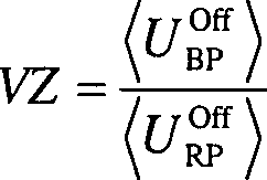
In
Abhängigkeit von dieser Verhältniszahl VZ wird
in einem Verfahrensschritt
Sowohl
bei der Referenzpumpe als auch bei der Betriebspumpe erfolgt die
Datenerfassung für die Histogramme
Während
der Betriebsphase III. der Kraftfahrzeugbremsanlage
Die
Kalibrierphase II. wird bei Bedarf periodisch wiederholt. Weiterhin
wird bei der Durchführung der Kalibrierung entweder automatisch
durch die Steuereinheit
Die
der Kalibrierphase II. und der Betriebsphase III. entsprechenden
Verfahrensabschnitte werden durch die als Mikrocontroller ausgebildete
Steuereinheit
![]()
![]()
Durch diese Normierung werden Schwankungen des Absolutwertes der Motorspannung UM ausgeglichen, die ansonsten die Messung beeinflussen würden.By this standardization fluctuations in the absolute value of the motor voltage U M are compensated, which would otherwise affect the measurement.
Nach
Abschluss des Testzeitraumes werden die Spannungswerte
An
das Histogramm
In
Die
ermittelte Kennlinie
- 11
- KraftfahrzeugbremsanlageMotor vehicle brake system
- 22
- HauptbremszylinderMaster Cylinder
- 44
- hydraulische Verbindunghydraulic connection
- 55
- Verteilvorrichtungdistributor
- 66
- Hydraulikeinheithydraulic unit
- 77
- Steuereinheitcontrol unit
- 88th
- Radbremsewheel brake
- 9, 109 10
- Auslassventiloutlet valve
- 1111
- Abzweigjunction
- 1212
- RücklaufanschlussReturn connection
- 1313
- NiederdruckspeicherLow-pressure accumulator
- 1414
- Pumpe oder RP, BPpump or RP, BP
- 1515
- Motorengine
- 1616
- Saugventilsuction
- 1717
- Druckventilpressure valve
- 1818
- DrehzahlsensorSpeed sensor
- 1919
- PulsPulse
- 2020
- Pulslückepulse gap
- 21–2621-26
- Verfahrensschrittstep
- I.I.
- Erprobungsphasetrial phase
- II.II.
- Kalibrierungsphasecalibration phase
- III.III.
- Betriebsphaseoperational phase
- AA
- ResttaktdauerRest Pulse_duration
- Ee
- Pulsweitepulse width
- GG
- Gaußsche VerteilungsfunktionGauss distribution function
- H(U Off / RP)H (U Off / RP)
- Histogrammhistogram
- H(U Off / BP)H (U Off / BP)
- Histogrammhistogram
- 〈U Off / RP〉<U Off / RP>
- MittelwertAverage
- 〈U Off / BP〉<U Off / BP>
- MittelwertAverage
- UOnF U OnF
- Parameterparameter
- UOff U Off
- Parameterparameter
- UFall U case
- Parameterparameter
- Umin U min
- Parameterparameter
- Usum U sum
- Parameterparameter
- UAver U Aver
- Parameterparameter
- Uslope U slope
- Parameterparameter
- Urise U rise
- Parameterparameter
- tFall t case
- Parameterparameter
- pv p v
- Vordruckform
- pv(U Off / RP) v p (U Off / RP)
- Kennliniecurve
- pv(U Off / BP) v p (U Off / BP)
- Kennliniecurve
- R1, R2, R3R1, R2, R3
- Richtungdirection
ZITATE ENTHALTEN IN DER BESCHREIBUNGQUOTES INCLUDE IN THE DESCRIPTION
Diese Liste der vom Anmelder aufgeführten Dokumente wurde automatisiert erzeugt und ist ausschließlich zur besseren Information des Lesers aufgenommen. Die Liste ist nicht Bestandteil der deutschen Patent- bzw. Gebrauchsmusteranmeldung. Das DPMA übernimmt keinerlei Haftung für etwaige Fehler oder Auslassungen.This list The documents listed by the applicant have been automated generated and is solely for better information recorded by the reader. The list is not part of the German Patent or utility model application. The DPMA takes over no liability for any errors or omissions.
Zitierte PatentliteraturCited patent literature
- - DE 102005041556 A1 [0003] DE 102005041556 A1 [0003]
Zitierte Nicht-PatentliteraturCited non-patent literature
- - Dubbel, Taschenbuch für den Maschinenbau, Springer Verlag, Heidelberg, 20. Aufl. 2001, ISBN 3-540-67777-1, Abschnitt Q/Fahrzeugtechnik [0002] - Dubbel, Paperback for Mechanical Engineering, Springer Verlag, Heidelberg, 20th ed. 2001, ISBN 3-540-67777-1, section Q / Fahrzeugtechnik [0002]
Claims (14)
Priority Applications (6)
| Application Number | Priority Date | Filing Date | Title |
|---|---|---|---|
| DE102007050662A DE102007050662A1 (en) | 2007-10-24 | 2007-10-24 | Method and device for calibrating or diagnosing a motor vehicle brake system with a clocked pump |
| PCT/EP2008/064284 WO2009053389A1 (en) | 2007-10-24 | 2008-10-22 | Method and device for the calibration or diagnosis of a motor vehicle brake system having a cyclically operated pump |
| DE502008003377T DE502008003377D1 (en) | 2007-10-24 | 2008-10-22 | METHOD AND DEVICE FOR CALIBRATING OR DIAGNOSING A MOTOR VEHICLE BRAKING SYSTEM WITH A PUMP ACTUATED |
| EP08842921A EP2205469B1 (en) | 2007-10-24 | 2008-10-22 | Method and device for the calibration or diagnosis of a motor vehicle brake system having a cyclically operated pump |
| US12/739,456 US8301331B2 (en) | 2007-10-24 | 2008-10-22 | Method and device for the calibration or diagnosis of a motor vehicle brake system having a cyclically operated pump |
| AT08842921T ATE507123T1 (en) | 2007-10-24 | 2008-10-22 | METHOD AND DEVICE FOR CALIBRATION OR DIAGNOSIS OF A MOTOR VEHICLE BRAKE SYSTEM WITH A CLOCKED PUMP |
Applications Claiming Priority (1)
| Application Number | Priority Date | Filing Date | Title |
|---|---|---|---|
| DE102007050662A DE102007050662A1 (en) | 2007-10-24 | 2007-10-24 | Method and device for calibrating or diagnosing a motor vehicle brake system with a clocked pump |
Publications (1)
| Publication Number | Publication Date |
|---|---|
| DE102007050662A1 true DE102007050662A1 (en) | 2009-04-30 |
Family
ID=40266141
Family Applications (2)
| Application Number | Title | Priority Date | Filing Date |
|---|---|---|---|
| DE102007050662A Withdrawn DE102007050662A1 (en) | 2007-10-24 | 2007-10-24 | Method and device for calibrating or diagnosing a motor vehicle brake system with a clocked pump |
| DE502008003377T Active DE502008003377D1 (en) | 2007-10-24 | 2008-10-22 | METHOD AND DEVICE FOR CALIBRATING OR DIAGNOSING A MOTOR VEHICLE BRAKING SYSTEM WITH A PUMP ACTUATED |
Family Applications After (1)
| Application Number | Title | Priority Date | Filing Date |
|---|---|---|---|
| DE502008003377T Active DE502008003377D1 (en) | 2007-10-24 | 2008-10-22 | METHOD AND DEVICE FOR CALIBRATING OR DIAGNOSING A MOTOR VEHICLE BRAKING SYSTEM WITH A PUMP ACTUATED |
Country Status (5)
| Country | Link |
|---|---|
| US (1) | US8301331B2 (en) |
| EP (1) | EP2205469B1 (en) |
| AT (1) | ATE507123T1 (en) |
| DE (2) | DE102007050662A1 (en) |
| WO (1) | WO2009053389A1 (en) |
Cited By (4)
| Publication number | Priority date | Publication date | Assignee | Title |
|---|---|---|---|---|
| WO2010122132A1 (en) | 2009-04-23 | 2010-10-28 | Continental Teves Ag & Co. Ohg | Method for calibrating a pump motor in a pressure control system |
| DE102010039818A1 (en) * | 2010-08-26 | 2012-03-01 | Continental Teves Ag & Co. Ohg | Method for pressure sensorless pressure measurement in a pressure control unit of a motor vehicle brake system |
| DE102018203181A1 (en) | 2018-03-02 | 2019-09-05 | Volkswagen Aktiengesellschaft | Method for checking the correct installation of an electronic parking brake of a motor vehicle |
| CN113565832A (en) * | 2021-07-19 | 2021-10-29 | 奇瑞新能源汽车股份有限公司 | Hydraulic calibration method and device for electronic booster of automatic driving vehicle and vehicle |
Families Citing this family (5)
| Publication number | Priority date | Publication date | Assignee | Title |
|---|---|---|---|---|
| DE102007050662A1 (en) * | 2007-10-24 | 2009-04-30 | Continental Teves Ag & Co. Ohg | Method and device for calibrating or diagnosing a motor vehicle brake system with a clocked pump |
| DE102010032929A1 (en) * | 2010-07-30 | 2012-02-02 | Lucas Automotive Gmbh | Method for operating an electrically controllable brake system |
| JP2012101676A (en) * | 2010-11-10 | 2012-05-31 | Hitachi Automotive Systems Ltd | Brake control system |
| JP5717708B2 (en) * | 2012-11-16 | 2015-05-13 | 日信工業株式会社 | Brake hydraulic pressure control device for vehicles |
| CN111308932B (en) * | 2020-02-25 | 2021-08-31 | 北京百度网讯科技有限公司 | Calibration method, device and equipment of brake system and storage medium |
Citations (1)
| Publication number | Priority date | Publication date | Assignee | Title |
|---|---|---|---|---|
| DE102005041556A1 (en) | 2005-09-01 | 2007-03-08 | Continental Teves Ag & Co. Ohg | Method for determining an admission pressure in a motor vehicle brake system |
Family Cites Families (35)
| Publication number | Priority date | Publication date | Assignee | Title |
|---|---|---|---|---|
| US4302812A (en) * | 1980-03-31 | 1981-11-24 | Bell Telephone Laboratories, Incorporated | Analog signal level monitor |
| US4745562A (en) * | 1985-08-16 | 1988-05-17 | Schlumberger, Limited | Signal processing disparity resolution |
| DE3630327C2 (en) * | 1986-09-05 | 1996-04-25 | Lincoln Gmbh | Central lubrication system for vehicles |
| GB2245038B (en) * | 1990-06-07 | 1994-03-23 | Toyota Motor Co Ltd | Device for detecting accumulator fluid leakage through control valve and restoring proper valve seating |
| DE4429373A1 (en) * | 1994-08-22 | 1996-02-29 | Bosch Gmbh Robert | Device for controlling a consumer |
| DE19528697A1 (en) * | 1995-08-04 | 1997-02-06 | Bosch Gmbh Robert | Method and device for determining a pressure variable |
| DE19651154C2 (en) | 1995-12-16 | 2003-02-06 | Bosch Gmbh Robert | Method and device for controlling a brake system |
| US6092992A (en) * | 1996-10-24 | 2000-07-25 | Imblum; Gregory G. | System and method for pump control and fault detection |
| DE19705619A1 (en) * | 1997-02-14 | 1998-08-20 | Bosch Gmbh Robert | Method and device for controlling the brake force distribution in a motor vehicle |
| US6659730B2 (en) * | 1997-11-07 | 2003-12-09 | Westport Research Inc. | High pressure pump system for supplying a cryogenic fluid from a storage tank |
| DE19818174C2 (en) * | 1998-04-23 | 2000-03-02 | Bosch Gmbh Robert | Methods and devices for controlling a pump for supplying auxiliary pressure to a vehicle brake system |
| US5971502A (en) * | 1998-06-04 | 1999-10-26 | Robert Bosch Technology Corp | Secondary braking control |
| US6188947B1 (en) * | 1998-11-09 | 2001-02-13 | Kelsey-Hayes Company | Closed loop speed control of ABS pump motor utilizing variable duty cycle and frequency |
| JP3284985B2 (en) * | 1998-12-03 | 2002-05-27 | トヨタ自動車株式会社 | Hydraulic brake device |
| US6446490B1 (en) * | 1998-12-28 | 2002-09-10 | Robert Bosch Gmbh | Method and device for determining the pressure in brake systems |
| JP3389877B2 (en) * | 1999-03-26 | 2003-03-24 | トヨタ自動車株式会社 | Pump device and hydraulic system |
| DE19917904C2 (en) * | 1999-04-20 | 2001-06-07 | Bosch Gmbh Robert | Method and device for controlling a pump for auxiliary pressure supply to a vehicle brake system and corresponding vehicle brake system |
| DE19946777B4 (en) * | 1999-09-29 | 2008-01-10 | Robert Bosch Gmbh | Method and device for estimating a form in a motor vehicle brake system |
| US6529135B1 (en) * | 1999-10-12 | 2003-03-04 | Csi Technology, Inc. | Integrated electric motor monitor |
| US6604909B2 (en) * | 2001-03-27 | 2003-08-12 | Aquatec Water Systems, Inc. | Diaphragm pump motor driven by a pulse width modulator circuit and activated by a pressure switch |
| WO2003066405A1 (en) * | 2002-02-07 | 2003-08-14 | Continental Teves Ag & Co.Ohg | Method for determining or calibrating the brake control characteristic of a vacuum brake booster |
| JP2005517570A (en) * | 2002-02-14 | 2005-06-16 | コンティネンタル・テーベス・アクチエンゲゼルシヤフト・ウント・コンパニー・オッフェネ・ハンデルスゲゼルシヤフト | How to adjust set variable brake pressure |
| US6741056B1 (en) * | 2002-05-15 | 2004-05-25 | Skc, Inc. | Air sampler with compensating pump motor speed |
| US7231319B2 (en) * | 2003-06-18 | 2007-06-12 | Eaton Corporation | System and method for proactive motor wellness diagnosis based on potential cavitation faults |
| US20060202552A1 (en) | 2003-07-11 | 2006-09-14 | Continental Teves Ag & Co.Ohg | Electronic control method for a slip-controlled motor vehicle brake system |
| JP4457618B2 (en) * | 2003-09-25 | 2010-04-28 | 株式会社アドヴィックス | Control device for pump drive motor |
| EP1585205B1 (en) * | 2004-04-09 | 2017-12-06 | Regal Beloit America, Inc. | Pumping apparatus and method of detecting an entrapment in a pumping apparatus |
| US8133034B2 (en) * | 2004-04-09 | 2012-03-13 | Regal Beloit Epc Inc. | Controller for a motor and a method of controlling the motor |
| US7412842B2 (en) * | 2004-04-27 | 2008-08-19 | Emerson Climate Technologies, Inc. | Compressor diagnostic and protection system |
| DE102004058726A1 (en) * | 2004-12-06 | 2006-06-08 | Lucas Automotive Gmbh | Pressure generator for a vehicle brake system and mounting method for the pressure generator |
| JP4618169B2 (en) * | 2006-03-13 | 2011-01-26 | 株式会社アドヴィックス | Brake control device for vehicle |
| GB0614534D0 (en) * | 2006-07-21 | 2006-08-30 | Artemis Intelligent Power Ltd | Fluid power distribution and control system |
| US20080095638A1 (en) * | 2006-10-13 | 2008-04-24 | A.O. Smith Corporation | Controller for a motor and a method of controlling the motor |
| DE102007050662A1 (en) * | 2007-10-24 | 2009-04-30 | Continental Teves Ag & Co. Ohg | Method and device for calibrating or diagnosing a motor vehicle brake system with a clocked pump |
| US8160827B2 (en) * | 2007-11-02 | 2012-04-17 | Emerson Climate Technologies, Inc. | Compressor sensor module |
-
2007
- 2007-10-24 DE DE102007050662A patent/DE102007050662A1/en not_active Withdrawn
-
2008
- 2008-10-22 DE DE502008003377T patent/DE502008003377D1/en active Active
- 2008-10-22 US US12/739,456 patent/US8301331B2/en active Active
- 2008-10-22 AT AT08842921T patent/ATE507123T1/en active
- 2008-10-22 EP EP08842921A patent/EP2205469B1/en active Active
- 2008-10-22 WO PCT/EP2008/064284 patent/WO2009053389A1/en active Application Filing
Patent Citations (1)
| Publication number | Priority date | Publication date | Assignee | Title |
|---|---|---|---|---|
| DE102005041556A1 (en) | 2005-09-01 | 2007-03-08 | Continental Teves Ag & Co. Ohg | Method for determining an admission pressure in a motor vehicle brake system |
Non-Patent Citations (1)
| Title |
|---|
| Dubbel, Taschenbuch für den Maschinenbau, Springer Verlag, Heidelberg, 20. Aufl. 2001, ISBN 3-540-67777-1, Abschnitt Q/Fahrzeugtechnik |
Cited By (6)
| Publication number | Priority date | Publication date | Assignee | Title |
|---|---|---|---|---|
| WO2010122132A1 (en) | 2009-04-23 | 2010-10-28 | Continental Teves Ag & Co. Ohg | Method for calibrating a pump motor in a pressure control system |
| DE102010028083A1 (en) | 2009-04-23 | 2010-11-11 | Continental Teves Ag & Co. Ohg | Method for calibrating a pump motor in a pressure control system |
| DE102010039818A1 (en) * | 2010-08-26 | 2012-03-01 | Continental Teves Ag & Co. Ohg | Method for pressure sensorless pressure measurement in a pressure control unit of a motor vehicle brake system |
| US8527176B2 (en) | 2010-08-26 | 2013-09-03 | Continental Teves Ag & Co. Ohg | Method for measuring pressure in a pressure regulation unit of a motor vehicle braking system, and a motor vehicle braking system in which the method is implemented |
| DE102018203181A1 (en) | 2018-03-02 | 2019-09-05 | Volkswagen Aktiengesellschaft | Method for checking the correct installation of an electronic parking brake of a motor vehicle |
| CN113565832A (en) * | 2021-07-19 | 2021-10-29 | 奇瑞新能源汽车股份有限公司 | Hydraulic calibration method and device for electronic booster of automatic driving vehicle and vehicle |
Also Published As
| Publication number | Publication date |
|---|---|
| DE502008003377D1 (en) | 2011-06-09 |
| US20110184606A1 (en) | 2011-07-28 |
| EP2205469A1 (en) | 2010-07-14 |
| ATE507123T1 (en) | 2011-05-15 |
| US8301331B2 (en) | 2012-10-30 |
| WO2009053389A1 (en) | 2009-04-30 |
| EP2205469B1 (en) | 2011-04-27 |
Similar Documents
| Publication | Publication Date | Title |
|---|---|---|
| EP2205469B1 (en) | Method and device for the calibration or diagnosis of a motor vehicle brake system having a cyclically operated pump | |
| DE112012005188B4 (en) | Brake condition diagnostic device for electromagnetic brake and related method | |
| DE102005014097A1 (en) | Method for calibrating the current / opening characteristic of an electrically controllable, analogously regulating hydraulic valve | |
| WO2018011021A1 (en) | Diagnostic method for at least one component of a motor vehicle | |
| EP2822826A1 (en) | Method for calibrating analog-controlled hydraulic valves and brake system comprising an electronic control and regulating unit in which the method is carried out | |
| DE102012205576A1 (en) | Method for providing the clamping force generated by a parking brake | |
| EP2608993B1 (en) | Method for measuring pressure, without pressure sensors, in a pressure regulation unit of a motor vehicle braking system, and a motor vehicle braking system comprising a pressure regulation unit in which said method is implemented | |
| EP2152555B1 (en) | Correction method for the correction of characteristic curves for analogized hydraulic valves in motor vehicle braking systems | |
| EP1062137B1 (en) | Method for compensating the temperature dependence of an inductive resistance of a valve coil | |
| WO2007025951A1 (en) | Method for determining initial pressure in a motor vehicle braking system | |
| DE102011077313A1 (en) | Method for operating a brake system and brake system | |
| DE102006015483A1 (en) | Controlling method e.g. for controlling braking system of vehicle, involves having vacuum brake booster and vacuum source with variable triggering threshold value dependent upon vacuum level or vacuum gradients | |
| WO2005007475A1 (en) | Electronic control method for a slip-controlled motor vehicle brake system | |
| EP2763876B1 (en) | Method for determining a model upstream pressure by means of a mathematical model in an electronically regulated motor vehicle brake system | |
| WO2010122132A1 (en) | Method for calibrating a pump motor in a pressure control system | |
| EP1937529A1 (en) | Method for determining the wheel pressure in an electronically actuable motor vehicle brake control system | |
| EP3810465A1 (en) | Method for monitoring a hydraulic brake system for a motor vehicle and brake system | |
| DE102004048121A1 (en) | Method for adapting an actual characteristic curve or actual characteristic field characterizing the mode of operation of a hydrodynamic component to a predefined or predefinable desired characteristic curve or characteristic diagram in the final acceptance of the hydrodynamic component | |
| DE102011080227A1 (en) | Method for optimizing printing accuracy | |
| DE102020212838A1 (en) | Procedure for valve calibration in the filled brake system | |
| DE102007034113B4 (en) | Method for calibrating a hydraulic pump | |
| EP1901081A1 (en) | Device and method for determining the status of a battery | |
| DE102011082635A1 (en) | Method for recognizing incorrectly determined pump control value in hydraulic brake system of motor vehicle, involves detecting incorrectly determined pump control value based on control value with respect to reference parameter | |
| DE102018000906A1 (en) | Hybrid electric plunger valve | |
| DE102022209076A1 (en) | Method for determining an external power cylinder pressure |
Legal Events
| Date | Code | Title | Description |
|---|---|---|---|
| OM8 | Search report available as to paragraph 43 lit. 1 sentence 1 patent law | ||
| R005 | Application deemed withdrawn due to failure to request examination | ||
| R005 | Application deemed withdrawn due to failure to request examination |
Effective date: 20141025 |