DE102006049552B4 - Device for applying film materials to paper documents - Google Patents
Device for applying film materials to paper documents Download PDFInfo
- Publication number
- DE102006049552B4 DE102006049552B4 DE102006049552.7A DE102006049552A DE102006049552B4 DE 102006049552 B4 DE102006049552 B4 DE 102006049552B4 DE 102006049552 A DE102006049552 A DE 102006049552A DE 102006049552 B4 DE102006049552 B4 DE 102006049552B4
- Authority
- DE
- Germany
- Prior art keywords
- ultrasonic
- carrier film
- sonotrode
- ultrasonic sonotrode
- anvil element
- Prior art date
- Legal status (The legal status is an assumption and is not a legal conclusion. Google has not performed a legal analysis and makes no representation as to the accuracy of the status listed.)
- Expired - Fee Related
Links
- 239000000463 material Substances 0.000 title claims abstract description 20
- 239000004831 Hot glue Substances 0.000 claims abstract description 12
- 238000010438 heat treatment Methods 0.000 claims abstract description 5
- 238000002604 ultrasonography Methods 0.000 description 14
- 238000000034 method Methods 0.000 description 5
- 239000002131 composite material Substances 0.000 description 3
- 238000006073 displacement reaction Methods 0.000 description 3
- 238000010030 laminating Methods 0.000 description 3
- 238000003475 lamination Methods 0.000 description 2
- 239000004822 Hot adhesive Substances 0.000 description 1
- 240000007594 Oryza sativa Species 0.000 description 1
- 235000007164 Oryza sativa Nutrition 0.000 description 1
- 150000001875 compounds Chemical class 0.000 description 1
- 230000001419 dependent effect Effects 0.000 description 1
- 239000011888 foil Substances 0.000 description 1
- 230000003993 interaction Effects 0.000 description 1
- 239000005001 laminate film Substances 0.000 description 1
- 238000003754 machining Methods 0.000 description 1
- 238000004519 manufacturing process Methods 0.000 description 1
- 239000005022 packaging material Substances 0.000 description 1
- 230000002093 peripheral effect Effects 0.000 description 1
- 235000009566 rice Nutrition 0.000 description 1
- 238000007789 sealing Methods 0.000 description 1
Images
Classifications
-
- B—PERFORMING OPERATIONS; TRANSPORTING
- B32—LAYERED PRODUCTS
- B32B—LAYERED PRODUCTS, i.e. PRODUCTS BUILT-UP OF STRATA OF FLAT OR NON-FLAT, e.g. CELLULAR OR HONEYCOMB, FORM
- B32B37/00—Methods or apparatus for laminating, e.g. by curing or by ultrasonic bonding
- B32B37/06—Methods or apparatus for laminating, e.g. by curing or by ultrasonic bonding characterised by the heating method
-
- B—PERFORMING OPERATIONS; TRANSPORTING
- B29—WORKING OF PLASTICS; WORKING OF SUBSTANCES IN A PLASTIC STATE IN GENERAL
- B29C—SHAPING OR JOINING OF PLASTICS; SHAPING OF MATERIAL IN A PLASTIC STATE, NOT OTHERWISE PROVIDED FOR; AFTER-TREATMENT OF THE SHAPED PRODUCTS, e.g. REPAIRING
- B29C63/00—Lining or sheathing, i.e. applying preformed layers or sheathings of plastics; Apparatus therefor
- B29C63/02—Lining or sheathing, i.e. applying preformed layers or sheathings of plastics; Apparatus therefor using sheet or web-like material
-
- B—PERFORMING OPERATIONS; TRANSPORTING
- B32—LAYERED PRODUCTS
- B32B—LAYERED PRODUCTS, i.e. PRODUCTS BUILT-UP OF STRATA OF FLAT OR NON-FLAT, e.g. CELLULAR OR HONEYCOMB, FORM
- B32B37/00—Methods or apparatus for laminating, e.g. by curing or by ultrasonic bonding
- B32B37/12—Methods or apparatus for laminating, e.g. by curing or by ultrasonic bonding characterised by using adhesives
- B32B37/1207—Heat-activated adhesive
- B32B2037/1215—Hot-melt adhesive
-
- B—PERFORMING OPERATIONS; TRANSPORTING
- B32—LAYERED PRODUCTS
- B32B—LAYERED PRODUCTS, i.e. PRODUCTS BUILT-UP OF STRATA OF FLAT OR NON-FLAT, e.g. CELLULAR OR HONEYCOMB, FORM
- B32B2310/00—Treatment by energy or chemical effects
- B32B2310/028—Treatment by energy or chemical effects using vibration, e.g. sonic or ultrasonic
-
- B—PERFORMING OPERATIONS; TRANSPORTING
- B32—LAYERED PRODUCTS
- B32B—LAYERED PRODUCTS, i.e. PRODUCTS BUILT-UP OF STRATA OF FLAT OR NON-FLAT, e.g. CELLULAR OR HONEYCOMB, FORM
- B32B2429/00—Carriers for sound or information
-
- B—PERFORMING OPERATIONS; TRANSPORTING
- B32—LAYERED PRODUCTS
- B32B—LAYERED PRODUCTS, i.e. PRODUCTS BUILT-UP OF STRATA OF FLAT OR NON-FLAT, e.g. CELLULAR OR HONEYCOMB, FORM
- B32B37/00—Methods or apparatus for laminating, e.g. by curing or by ultrasonic bonding
- B32B37/12—Methods or apparatus for laminating, e.g. by curing or by ultrasonic bonding characterised by using adhesives
- B32B37/1207—Heat-activated adhesive
-
- B—PERFORMING OPERATIONS; TRANSPORTING
- B42—BOOKBINDING; ALBUMS; FILES; SPECIAL PRINTED MATTER
- B42D—BOOKS; BOOK COVERS; LOOSE LEAVES; PRINTED MATTER CHARACTERISED BY IDENTIFICATION OR SECURITY FEATURES; PRINTED MATTER OF SPECIAL FORMAT OR STYLE NOT OTHERWISE PROVIDED FOR; DEVICES FOR USE THEREWITH AND NOT OTHERWISE PROVIDED FOR; MOVABLE-STRIP WRITING OR READING APPARATUS
- B42D25/00—Information-bearing cards or sheet-like structures characterised by identification or security features; Manufacture thereof
Landscapes
- Lining Or Joining Of Plastics Or The Like (AREA)
- Credit Cards Or The Like (AREA)
- Folding Of Thin Sheet-Like Materials, Special Discharging Devices, And Others (AREA)
Abstract
Vorrichtung zum fortlaufenden Aufbringen einer Vielzahl von auf einem gemeinsamen fortbewegbaren Trägerfolienband (4) angeordneten flach ausgebildeten Folien- und/oder Bildmaterialien auf eine Vielzahl von zu beschichtenden Oberflächen (2a) mittels eines dazwischen angeordneten Heißklebstoffes, gekennzeichnet durch eine Ultraschallsonotrode (5, 6), die an einer den Folien- und/oder Bildmaterialien abgewandten Oberfläche (4a) des Trägerfolienbandes (4) angeordnet ist, und deren Ultraschallschwingung durch eine Übertragung von Energie zur Erwärmung des Heißklebstoffes führt, wobei die Ultraschallsonotrode (5, 6) und/oder ein an einer der Ultraschallsonotrode (5, 6) abgewandten Unterseite (2b) eines Papierdokuments (2) angeordnetes Ambosselement (3, 8) entlang einer Ebene der Oberfläche (2a) verschiebbar sind, und die Ultraschallsonotrode (5, 6) beidseitig mit zum Ambosselement (3, 8) hinwirkenden druckbeaufschlagten Anpresswalzen (7a, 7b) versehen ist und die Ultraschallsonotrode (5, 6) und die Anpresswalzen (7a, 7b) in der Ebene der Oberfläche (2a) in Verlaufsrichtung des Trägerfolienbandes (4) zeitgleich verschiebbar sind.Apparatus for continuously applying a plurality of flatly formed film and / or image materials arranged on a common, moveable carrier film strip (4) onto a multiplicity of surfaces (2a) to be coated by means of an intermediate hot melt adhesive, characterized by an ultrasonic sonotrode (5, 6), which is arranged on a side facing away from the film and / or image materials surface (4a) of the carrier film strip (4), and whose ultrasonic vibration leads by a transfer of energy for heating the hot melt adhesive, wherein the ultrasonic sonotrode (5, 6) and / or on one of the ultrasonic sonotrode (5, 6) facing away from bottom (2b) of a paper document (2) arranged anvil element (3, 8) along a plane of the surface (2a) are displaceable, and the ultrasonic sonotrode (5, 6) on both sides with the anvil element (3 , 8) acting pressurized pressure rollers (7a, 7b) is provided and the ultrasonic sonotro de (5, 6) and the pressure rollers (7a, 7b) in the plane of the surface (2a) in the direction of the carrier film strip (4) are simultaneously displaced.
Description
Die Erfindung betrifft eine Vorrichtung zum fortlaufenden Aufbringen einer Vielzahl von auf einem gemeinsamen fortbewegbaren Trägerfolienband angeordneten flach ausgebildeten Folien- und/oder Bildmaterialien auf einer Vielzahl von zu beschichtenden Papierdokumentenoberflächen mittels eines dazwischen angeordneten Heißklebstoffes gemäß dem Oberbegriff des Patentanspruches 1.The invention relates to a device for the continuous application of a plurality of flat-shaped film and / or image materials arranged on a common moveable carrier film strip on a multiplicity of paper document surfaces to be coated by means of an interposed hot melt adhesive according to the preamble of
Derartige Aufbring- bzw. Laminierungsvorgänge, sofern es sich um die Auftragung von Folien, vorzugsweise mehrschichtige Folienverbünde handelt, sind bei der Verwendung von zu laminierenden Papierdokumenten, wie es beispielsweise bei einzelnen Papierseiten eines Reisepasses der Fall ist, bisher mittels eines beheizten Stempelelementes und einem gegenüberliegenden Ambosselement durchgeführt worden.Such application or lamination processes, insofar as it concerns the application of films, preferably multi-layer film composites, are heretofore by means of a heated stamp element and an opposite one when using paper documents to be laminated, as is the case for example on individual paper pages of a passport Anvil element has been performed.
Derartige Stempelelemente sind unterseitig mit einer der zu laminierenden Papierseite entsprechenden Fläche ausgebildet und müssen bei gleichbleibender Temperatur über eine vorbestimmbare Zeitspanne erwärmt bleiben, um eine im Bezug auf die Flächenanteile und die Zeitabschnitte gleichbleibende Temperatur für eine gleichmäßige und zuverlässige Erwärmung eines Heißklebstoffes zu erreichen.Such stamping elements are formed on the underside with a corresponding surface to be laminated paper side and must remain heated at a constant temperature over a predeterminable period of time to achieve a constant with respect to the surface portions and the time temperature for a uniform and reliable heating of a hot melt adhesive.
Der Heißklebstoff ist hierbei an der Unterseite des Folienmaterials angeordnet.The hot melt adhesive is in this case arranged on the underside of the film material.
Ein derartiges im Bezug auf eine vorbestimmbare Zeitspanne und eine bestimmte Flächengröße gleichbleibendes Erwärmen des Stempelelementes ist insbesondere bei einer großen Serienfertigung nicht durchführbar, wenn beispielsweise die Laminierungsmaschine einen kurzzeitigen Stillstand aufgrund eines fehlerhaften Vorganges erfährt. Dies führt zu unzuverlässigen und nicht dauerhaften Heißklebstoffverbindungen dieser Folien bzw. Folienverbünde mit der Oberfläche des Papierdokumentes.Such a heating of the stamp element, which remains constant with respect to a predeterminable time span and a certain surface size, can not be carried out, in particular in the case of large series production, if, for example, the laminating machine experiences a brief standstill due to a faulty process. This leads to unreliable and non-permanent hot-melt adhesive compounds of these films or film composites with the surface of the paper document.
Aus
Aus der
Eine detaillierte Wiedergabe einer Vorrichtung zum Ausführen eines derartigen Verfahrens ist in
Demzufolge liegt der vorliegenden Erfindung die Aufgabe zugrunde, eine Vorrichtung zum fortlaufenden Aufbringen einer Vielzahl von auf einem gemeinsamen fortbewegbaren Trägerfolienband angeordneten flach ausgebildeten Folien- und/oder Bildmaterialien auf einer Vielzahl von zu beschichtenden Papierdokumentenoberflächen mittels eines dazwischen angeordneten Heißklebstoffes zur Verfügung zu stellen, welche eine dauerhafte, zuverlässige und auf einfache Weise durchführbare folienartige Materialaufbringung auf ein Papierdokument ermöglicht, wobei in geringer Zeit eine hohe Zahl an Folien- und/oder Bildmaterialien auf die Papierdokumente übertragen werden sollen, ohne dass hierbei eine Verformung der Papierdokumente stattfindet.Accordingly, it is an object of the present invention to provide an apparatus for continuously applying a plurality of flatly formed film and / or image materials disposed on a common traveling carrier film ribbon to a plurality of paper document surfaces to be coated by means of a hot melt adhesive therebetween allows durable, reliable and easy to carry out sheet-like material application to a paper document, with a high number of film and / or image materials to be transferred to the paper documents in a short time, without this takes place a deformation of the paper documents.
Diese Aufgabe wird durch die Merkmale des Patentanspruches 1 gelöst.This object is solved by the features of
Ein wesentlicher Punkt der Erfindung liegt darin, dass bei einer Vorrichtung zum fortlaufenden Aufbringen einer Vielzahl von auf einem gemeinsamen fortbewegbaren Trägerfolienband angeordneten flach ausgebildeten Folien- und/oder Bildmaterialien auf einer Vielzahl von zu beschichtenden Oberflächen bzw. Papierdokumentenoberflächen mittels eines dazwischen angeordneten Heißklebstoffes eine Ultraschallsonotrode, die an einer den Folien- und/oder Bildmaterialien abgewandten Oberfläche bzw. Unterseite des Trägerfolienbandes angeordnet ist, und deren Ultraschallschwingung durch eine Übertragung von Energie zur Erwärmung des Heißklebstoffes führt, verwendet wird.An essential point of the invention is that, in an apparatus for continuously applying a plurality of flatly formed film and / or image materials disposed on a common traveling carrier sheet, on a plurality of surfaces to be coated or paper document surfaces by means of a hot melt adhesive therebetween, an ultrasonic sonotrode, which is arranged on a side facing away from the film and / or image materials surface or underside of the carrier film strip, and the ultrasonic vibration leads by a transfer of energy to heat the hot melt adhesive, is used.
Die Ultraschallsonotrode weist hierbei zu beiden Seiten, also in Transportbandlängsrichtung gesehen vor und hinter der Ultraschallsonotrode, Anpresswalzen auf, die eine Druckkraft zu einem Ambosselement, welches an einer der Ultraschallsonotrode abgewandten Oberfläche bzw. Unterseite des Papierdokumentes angeordnet ist, aufweist. Hierdurch führen die Anpresswalzen eine Druckbeaufschlagung unter gleichzeitiger Ultraschallschwingungsbeaufschlagung vorteilhaft durch, wobei die Ultraschallsonotrode und/oder das Ambosselement entlang einer Ebene der Oberfläche des Papierdokuments verschiebbar sind.The ultrasound sonotrode has in this case on both sides, so seen in the conveyor belt longitudinal direction in front of and behind the ultrasonic sonotrode, pressure rollers, which has a compressive force to an anvil member, which is disposed on a side facing away from the ultrasound sonotrode surface or bottom of the paper document. As a result, the pressure rollers advantageously carry out a pressurization with simultaneous application of ultrasonic vibration, wherein the ultrasound sonotrode and / or the anvil element are displaceable along a plane of the surface of the paper document.
Die Ultraschallsonotrode und die beidseitig angeordneten Anpresswalzen, welche ebenso in doppelter oder dreifacher Ausführung auf beiden Seiten der Ultraschallsonotrode angeordnet sein können, sind in der Ebene der Oberfläche des Papierdokumentes über die Oberfläche hinweg zeitgleich gegenüber dem ortsfesten Papierdokument verschiebbar. Die Verschiebungsrichtung dient zum flächigen Abfahren der Heißklebstofffläche, welche an der Unterseite der Folien- und/oder Bildmaterialien angeordnet ist.The ultrasound sonotrode and the pressure rollers arranged on both sides, which can likewise be arranged in double or triple form on both sides of the ultrasound sonotrode, are in the plane of the surface of the Paper document across the surface away at the same time against the stationary paper document displaced. The displacement direction serves to extend the hot-adhesive surface in a planar manner, which is arranged on the underside of the film and / or image materials.
Eine Verschiebebewegung ist vorzugsweise in Verlaufsrichtung des Trägerfolienbandes durchzuführen, um hierdurch ein kontinuierliches fortlaufendes Aufbringungs- bzw. Laminierungsverfahren durch stetiges Abrollen und Auftragen des Trägerfolienbandes und gleichzeitiges Verschieben der Ultraschallsonotrode zu erhalten.A sliding movement is preferably carried out in the direction of travel of the carrier film strip, thereby to obtain a continuous continuous lamination or laminating process by continuously unrolling and applying the carrier film strip and simultaneously moving the ultrasonic sonotrode.
Gemäß einer weiteren Ausführungsform sind das Ambosselement und für das Papierdokument vorgesehene Auflageelemente, die beidseitig des Ambosselementes angeordnet sind, in der Ebene der Oberfläche des Papierdokumentes verschiebbar, während die Ultraschallsonotrode und die Anpresswalzen, welche den Druck in Richtung des Ambosselementes bzw. der Auflageelemente ausüben, ebenso in die gleiche Richtung gegenüber dem ortsfesten Papierdokument verschoben werden. Eine Verschiebung der Ultraschallsonotrode der Anpresswalzen entlang der Oberfläche des Papierdokumentes kann somit mit oder ohne dem Ambosselement und gegebenenfalls den Auflageflächenelementen verschoben werden, während das Papierdokument ortsfest eingespannt ist.According to a further embodiment, the anvil element and support elements provided for the paper document, which are arranged on both sides of the anvil element, are displaceable in the plane of the surface of the paper document, while the ultrasound sonotrode and the pressure rollers, which exert the pressure in the direction of the anvil element or the support elements, are also moved in the same direction relative to the stationary paper document. A displacement of the ultrasound sonotrode of the pressure rollers along the surface of the paper document can thus be displaced with or without the anvil element and optionally the contact surface elements, while the paper document is clamped in a stationary manner.
Das Ambosselement kann im Zusammenspiel mit zwei Auflageelementen, die beidseitig des Ambosselementes, also in Trägerlängsrichtung gesehen vor und hinter dem Ambosselement, angeordnet sind, als drehbare Antriebsambosswalze ausgebildet sein, auf deren Außenfläche oberseitig die Unterseite des Papierdokumentes ablegbar ist. Hierdurch kann ein Antrieb des Papierdokumentes unterhalb der Ultraschallsonotrode und der Anpresswalzen stattfinden. Des Weiteren kann die Ambosswalze ohne eigenen Antrieb angetrieben werden, wobei deren Umfangsgeschwindigkeit der Verfahrgeschwindigkeit der Ultraschallsonotrode entspricht.The anvil element can be designed as a rotatable drive anvil roller in interaction with two support elements, which are arranged on both sides of the anvil element, ie viewed in the longitudinal direction of carrier before and behind the anvil element, on the outer surface of the underside of the paper document can be placed. In this way, a drive of the paper document can take place below the ultrasound sonotrode and the pressure rollers. Furthermore, the anvil roller can be driven without its own drive, the peripheral speed of which corresponds to the travel speed of the ultrasound sonotrode.
Das restliche Trägerfolienband kann nach erfolgter UItraschallschwingungsbeaufschlagung von den aufgetragenen Folien- und/oder Bildmaterialien mittels eines Trennmessers, eines rakelartigen Messers oder dergleichen abgetrennt werden, um anschließend auf einer Aufwickelrolle als Restmaterial aufgewickelt zu werden.After the UItraschallschwingungsbeaufschlagung the remaining Trägerfolienband can be separated from the applied film and / or image materials by means of a separating knife, a squeegee blade or the like, to be subsequently wound on a take-up roll as a residual material.
Weitere vorteilhafte Ausführungsformen ergeben sich aus den Unteransprüchen.Further advantageous embodiments will become apparent from the dependent claims.
Vorteile und Zweckmäßigkeiten sind der nachfolgenden Beschreibung in Verbindung mit der Zeichnung zu entnehmen. Hierbei zeigen:Advantages and expediencies can be found in the following description in conjunction with the drawing. Hereby show:
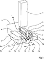
In
Ein Trägerfolienband
Eine Ultraschallsonotrode
Zu beiden Seiten, also vor und hinter der Ultrschallsonotrode
Hierbei wirkt die Ultraschallsonotrode
Die Ambosswalze
Mittels eines Rakelmessers bzw. eines rakelartigen Messers
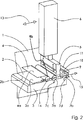
In
Diese Darstellung ist zu entnehmen, dass sich diese Vorrichtung gemäß der zweiten Ausführungsform der Erfindung im Gegensatz zu der Vorrichtung gemäß der ersten Ausführungsform der Erfindung durch eine verschiebbare Ultraschallsonotrode
Ebenso können die Anpressrollen
Somit unterscheidet sich die ersten von der zweiten Ausführungsform darin, dass hier eine Verschiebung der Ambosswalze
Welche dieser beiden Ausführungsformen angewendet wird, kann in Abhängigkeit von dem zur Verfügung stehenden Platz innerhalb einer Personalisierungsmaschine gewählt werden.Which of these two embodiments is used can be chosen depending on the available space within a personalization machine.
Sämtliche in den Anmeldungsunterlagen offenbarten Merkmale werden als erfindungswesentlich beansprucht, sofern sie einzeln oder in Kombination gegenüber dem Stand der Technik neu sind.All disclosed in the application documents features are claimed as essential to the invention, provided they are new individually or in combination over the prior art.
BezugszeichenlisteLIST OF REFERENCE NUMBERS
- 11
- Reisepasspassport
- 22
- Papierseitepaper side
- 2a2a
- obere Oberfläche der Papierseite bzw. Oberflächeupper surface of the paper side or surface
- 2b2 B
- untere Oberfläche der Papierseite bzw. Unterseitelower surface of the paper side or underside
- 3, 3a, 3b3, 3a, 3b
- Auflageelementesupport elements
- 44
- TrägerfolienbandCarrier foil strip
- 4a4a
- Oberfläche des TrägerfolienbandesSurface of the carrier film strip
- 4b4b
- Walzeroller
- 55
- Ultraschallsonotrodeultrasonic sonotrode
- 66
- Ultraschallgeneratorultrasonic generator
- 7a, 7b7a, 7b
- Anpresswalzenpressure rollers
- 7c, 7d7c, 7d
- Druckbeaufschlagungpressurization
- 88th
- Ambosswalzeanvil roll
- 8a8a
- Drehrichtung der AmbosswalzeDirection of rotation of the anvil roller
- 99
- Oberflächenabschnittsurface section
- 1010
- rakelartiges Messersqueegee knife
- 1111
- abtrennbare Bandteiledetachable band parts
- 12, 13, 14, 1512, 13, 14, 15
- Verschieberichtungenshifting directions
Claims (4)
Priority Applications (1)
| Application Number | Priority Date | Filing Date | Title |
|---|---|---|---|
| DE102006049552.7A DE102006049552B4 (en) | 2006-10-20 | 2006-10-20 | Device for applying film materials to paper documents |
Applications Claiming Priority (1)
| Application Number | Priority Date | Filing Date | Title |
|---|---|---|---|
| DE102006049552.7A DE102006049552B4 (en) | 2006-10-20 | 2006-10-20 | Device for applying film materials to paper documents |
Publications (2)
| Publication Number | Publication Date |
|---|---|
| DE102006049552A1 DE102006049552A1 (en) | 2008-04-24 |
| DE102006049552B4 true DE102006049552B4 (en) | 2015-06-03 |
Family
ID=39198406
Family Applications (1)
| Application Number | Title | Priority Date | Filing Date |
|---|---|---|---|
| DE102006049552.7A Expired - Fee Related DE102006049552B4 (en) | 2006-10-20 | 2006-10-20 | Device for applying film materials to paper documents |
Country Status (1)
| Country | Link |
|---|---|
| DE (1) | DE102006049552B4 (en) |
Families Citing this family (1)
| Publication number | Priority date | Publication date | Assignee | Title |
|---|---|---|---|---|
| CN117656532A (en) * | 2024-01-26 | 2024-03-08 | 太原科技大学 | A method and device for preparing carbon fiber prepreg lamination in an ultrasonic-assisted autoclave |
Citations (2)
| Publication number | Priority date | Publication date | Assignee | Title |
|---|---|---|---|---|
| DE19505298A1 (en) * | 1995-02-16 | 1996-08-22 | Ips Int Packaging Syst | Ultrasonic sealing |
| US5591298A (en) * | 1988-01-19 | 1997-01-07 | Kimberly-Clark Corporation | Machine for ultrasonic bonding |
-
2006
- 2006-10-20 DE DE102006049552.7A patent/DE102006049552B4/en not_active Expired - Fee Related
Patent Citations (2)
| Publication number | Priority date | Publication date | Assignee | Title |
|---|---|---|---|---|
| US5591298A (en) * | 1988-01-19 | 1997-01-07 | Kimberly-Clark Corporation | Machine for ultrasonic bonding |
| DE19505298A1 (en) * | 1995-02-16 | 1996-08-22 | Ips Int Packaging Syst | Ultrasonic sealing |
Also Published As
| Publication number | Publication date |
|---|---|
| DE102006049552A1 (en) | 2008-04-24 |
Similar Documents
| Publication | Publication Date | Title |
|---|---|---|
| DE3878287T2 (en) | DEVICE FOR APPLYING A TAPE. | |
| DD287451A5 (en) | FORM FILLING LOCKING MACHINE FOR THE AUTOMATIC MANUFACTURE OF A PREFERRED NUMBER OF FILLED AND SEALED FINISHED PACKAGING | |
| DE3610551A1 (en) | DEVICE FOR PRODUCING BENEFITS MADE FROM PLASTIC FILM LINES | |
| DE2345536A1 (en) | METHOD AND DEVICE FOR APPLYING FLEXIBLE STRIPS OF MATERIAL TO A MOVING WEB | |
| DD232880A5 (en) | laminating | |
| EP0201530B1 (en) | Method and device for hot forming a stratified synthetic plate | |
| DE19511698C1 (en) | Device for connecting a sealing film to a material web | |
| EP3603950B1 (en) | Apparatus for manufacturing corrugated cardboard | |
| DE1922341A1 (en) | Process for the manufacture of continuous sets of generally flat articles and apparatus for carrying out this process | |
| DE3516902C2 (en) | ||
| DE102006037189A1 (en) | A method of performing a roll change in a supply unit for feeding a sheet-like sheet to a packaging machine or the like processing machine and supply unit for performing this method | |
| DE60125402T2 (en) | CUTTING AND LAMINATING DEVICE FOR PRODUCING REINFORCED STRIPS | |
| DE4017906C2 (en) | ||
| DE202018104342U1 (en) | packaging machine | |
| EP2551078B1 (en) | Device for stamping with adjustable distance between the rolls | |
| DE102006049552B4 (en) | Device for applying film materials to paper documents | |
| DE19836211A1 (en) | Quasi-continuous rotary cutting of sheet comprises cutting out by rotary cutter segment with stamping action, interrupted by cyclic re-alignment under control, followed by re-acceleration to cutter roller speed | |
| DE1786641C2 (en) | Glue application machine for the production of corrugated cardboard or the like | |
| DE2048079C3 (en) | Method and device for cold welding (solid-state welding) of two workpieces | |
| DE3439374C2 (en) | Process for the production of corrugated cardboard and corrugated cardboard machine for carrying out the process | |
| DE102011108954A1 (en) | Punching station for use in in-line narrow web-label printing machine for punching self-adhesive labels, has counter punching cylinder provided with hydrostatic bearing, which is provided with pair of hydrostatic slide bearings | |
| DE112019004484B4 (en) | Air filter media manufacturing method and tool therefor and system for forming geometry in a filter media web. | |
| EP2877319B1 (en) | Method for structuring a press belt | |
| DE102011090189A1 (en) | Labeling device for applying e.g. security label to container e.g. can, has transmission element that is formed such that bonding agent is applied in surface region of transmission element | |
| DE2928847A1 (en) | DEVICE FOR PROCESSING A RAIL-SHAPED MATERIAL |
Legal Events
| Date | Code | Title | Description |
|---|---|---|---|
| OP8 | Request for examination as to paragraph 44 patent law | ||
| R018 | Grant decision by examination section/examining division | ||
| R081 | Change of applicant/patentee |
Owner name: MUEHLBAUER GMBH & CO. KG, DE Free format text: FORMER OWNER: MUEHLBAUER AG, 93426 RODING, DE |
|
| R082 | Change of representative |
Representative=s name: WUESTHOFF & WUESTHOFF, PATENTANWAELTE PARTG MB, DE |
|
| R020 | Patent grant now final | ||
| R119 | Application deemed withdrawn, or ip right lapsed, due to non-payment of renewal fee |