DE102005060552B4 - Injection device for fuel engines - Google Patents
Injection device for fuel engines Download PDFInfo
- Publication number
- DE102005060552B4 DE102005060552B4 DE102005060552A DE102005060552A DE102005060552B4 DE 102005060552 B4 DE102005060552 B4 DE 102005060552B4 DE 102005060552 A DE102005060552 A DE 102005060552A DE 102005060552 A DE102005060552 A DE 102005060552A DE 102005060552 B4 DE102005060552 B4 DE 102005060552B4
- Authority
- DE
- Germany
- Prior art keywords
- pressure
- way valve
- fuel
- valve
- injection
- Prior art date
- Legal status (The legal status is an assumption and is not a legal conclusion. Google has not performed a legal analysis and makes no representation as to the accuracy of the status listed.)
- Expired - Lifetime
Links
Classifications
-
- F—MECHANICAL ENGINEERING; LIGHTING; HEATING; WEAPONS; BLASTING
- F02—COMBUSTION ENGINES; HOT-GAS OR COMBUSTION-PRODUCT ENGINE PLANTS
- F02M—SUPPLYING COMBUSTION ENGINES IN GENERAL WITH COMBUSTIBLE MIXTURES OR CONSTITUENTS THEREOF
- F02M45/00—Fuel-injection apparatus characterised by having a cyclic delivery of specific time/pressure or time/quantity relationship
-
- F—MECHANICAL ENGINEERING; LIGHTING; HEATING; WEAPONS; BLASTING
- F02—COMBUSTION ENGINES; HOT-GAS OR COMBUSTION-PRODUCT ENGINE PLANTS
- F02M—SUPPLYING COMBUSTION ENGINES IN GENERAL WITH COMBUSTIBLE MIXTURES OR CONSTITUENTS THEREOF
- F02M47/00—Fuel-injection apparatus operated cyclically with fuel-injection valves actuated by fluid pressure
- F02M47/02—Fuel-injection apparatus operated cyclically with fuel-injection valves actuated by fluid pressure of accumulator-injector type, i.e. having fuel pressure of accumulator tending to open, and fuel pressure in other chamber tending to close, injection valves and having means for periodically releasing that closing pressure
- F02M47/027—Electrically actuated valves draining the chamber to release the closing pressure
-
- F—MECHANICAL ENGINEERING; LIGHTING; HEATING; WEAPONS; BLASTING
- F02—COMBUSTION ENGINES; HOT-GAS OR COMBUSTION-PRODUCT ENGINE PLANTS
- F02M—SUPPLYING COMBUSTION ENGINES IN GENERAL WITH COMBUSTIBLE MIXTURES OR CONSTITUENTS THEREOF
- F02M59/00—Pumps specially adapted for fuel-injection and not provided for in groups F02M39/00 -F02M57/00, e.g. rotary cylinder-block type of pumps
- F02M59/20—Varying fuel delivery in quantity or timing
-
- F—MECHANICAL ENGINEERING; LIGHTING; HEATING; WEAPONS; BLASTING
- F02—COMBUSTION ENGINES; HOT-GAS OR COMBUSTION-PRODUCT ENGINE PLANTS
- F02M—SUPPLYING COMBUSTION ENGINES IN GENERAL WITH COMBUSTIBLE MIXTURES OR CONSTITUENTS THEREOF
- F02M63/00—Other fuel-injection apparatus having pertinent characteristics not provided for in groups F02M39/00 - F02M57/00 or F02M67/00; Details, component parts, or accessories of fuel-injection apparatus, not provided for in, or of interest apart from, the apparatus of groups F02M39/00 - F02M61/00 or F02M67/00; Combination of fuel pump with other devices, e.g. lubricating oil pump
- F02M63/0003—Fuel-injection apparatus having a cyclically-operated valve for connecting a pressure source, e.g. constant pressure pump or accumulator, to an injection valve held closed mechanically, e.g. by springs, and automatically opened by fuel pressure
- F02M63/0005—Fuel-injection apparatus having a cyclically-operated valve for connecting a pressure source, e.g. constant pressure pump or accumulator, to an injection valve held closed mechanically, e.g. by springs, and automatically opened by fuel pressure using valves actuated by fluid pressure
-
- F—MECHANICAL ENGINEERING; LIGHTING; HEATING; WEAPONS; BLASTING
- F02—COMBUSTION ENGINES; HOT-GAS OR COMBUSTION-PRODUCT ENGINE PLANTS
- F02M—SUPPLYING COMBUSTION ENGINES IN GENERAL WITH COMBUSTIBLE MIXTURES OR CONSTITUENTS THEREOF
- F02M63/00—Other fuel-injection apparatus having pertinent characteristics not provided for in groups F02M39/00 - F02M57/00 or F02M67/00; Details, component parts, or accessories of fuel-injection apparatus, not provided for in, or of interest apart from, the apparatus of groups F02M39/00 - F02M61/00 or F02M67/00; Combination of fuel pump with other devices, e.g. lubricating oil pump
- F02M63/0003—Fuel-injection apparatus having a cyclically-operated valve for connecting a pressure source, e.g. constant pressure pump or accumulator, to an injection valve held closed mechanically, e.g. by springs, and automatically opened by fuel pressure
- F02M63/0007—Fuel-injection apparatus having a cyclically-operated valve for connecting a pressure source, e.g. constant pressure pump or accumulator, to an injection valve held closed mechanically, e.g. by springs, and automatically opened by fuel pressure using electrically actuated valves
-
- F—MECHANICAL ENGINEERING; LIGHTING; HEATING; WEAPONS; BLASTING
- F02—COMBUSTION ENGINES; HOT-GAS OR COMBUSTION-PRODUCT ENGINE PLANTS
- F02M—SUPPLYING COMBUSTION ENGINES IN GENERAL WITH COMBUSTIBLE MIXTURES OR CONSTITUENTS THEREOF
- F02M63/00—Other fuel-injection apparatus having pertinent characteristics not provided for in groups F02M39/00 - F02M57/00 or F02M67/00; Details, component parts, or accessories of fuel-injection apparatus, not provided for in, or of interest apart from, the apparatus of groups F02M39/00 - F02M61/00 or F02M67/00; Combination of fuel pump with other devices, e.g. lubricating oil pump
- F02M63/0012—Valves
- F02M63/0031—Valves characterized by the type of valves, e.g. special valve member details, valve seat details, valve housing details
- F02M63/0045—Three-way valves
-
- F—MECHANICAL ENGINEERING; LIGHTING; HEATING; WEAPONS; BLASTING
- F02—COMBUSTION ENGINES; HOT-GAS OR COMBUSTION-PRODUCT ENGINE PLANTS
- F02M—SUPPLYING COMBUSTION ENGINES IN GENERAL WITH COMBUSTIBLE MIXTURES OR CONSTITUENTS THEREOF
- F02M69/00—Low-pressure fuel-injection apparatus ; Apparatus with both continuous and intermittent injection; Apparatus injecting different types of fuel
- F02M69/16—Low-pressure fuel-injection apparatus ; Apparatus with both continuous and intermittent injection; Apparatus injecting different types of fuel characterised by means for metering continuous fuel flow to injectors or means for varying fuel pressure upstream of continuously or intermittently operated injectors
Landscapes
- Engineering & Computer Science (AREA)
- Chemical & Material Sciences (AREA)
- Combustion & Propulsion (AREA)
- Mechanical Engineering (AREA)
- General Engineering & Computer Science (AREA)
- Physics & Mathematics (AREA)
- Fluid Mechanics (AREA)
- Fuel-Injection Apparatus (AREA)
Abstract
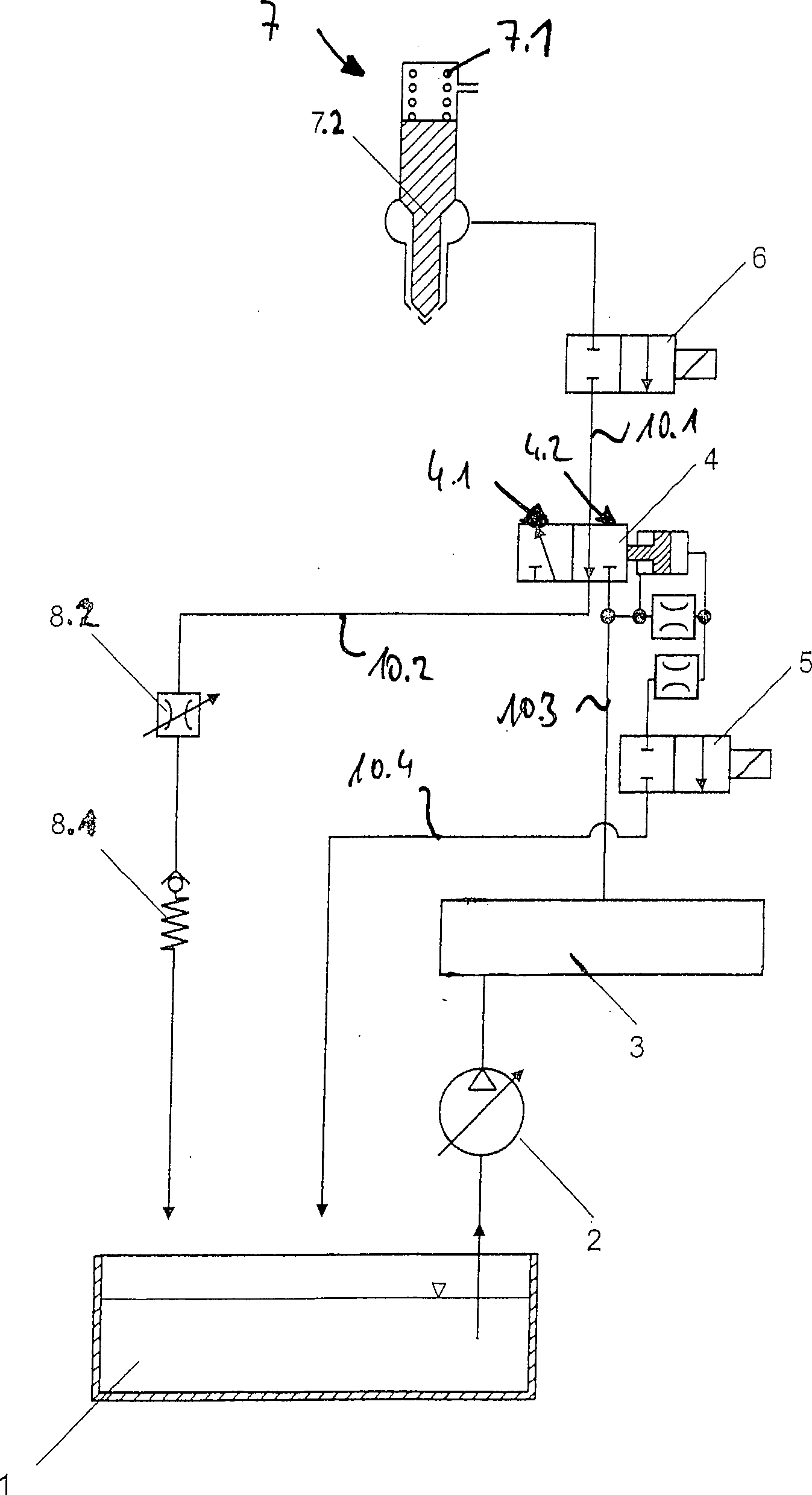
Einspritzvorrichtung für Brennstoffmotoren mit einem druckgesteuerten Einspritzventil (7), dem ein 2/2-Wegeventil (6) vorgeschaltet ist, welches einen Druckspeicher (3), in dem sich unter Druck stehender Kraftstoff befindet, mit dem druckgesteuerten Einspritzventil (7) verbindet oder davon trennt, dem 2/2-Wegeventil (6) ein 3/2-Wegeventil (4) in hydraulischer Strömungsrichtung vorgeschaltet ist, die beiden Wegeventile (4, 6) so schaltbar sind, dass das 3/2-Wegeventil (4) in einer Schaltstellung (4.1) den Druckspeicher (3) mit dem 2/2-Wegeventil (6) verbindet und in einer zweiten Stellung (4.2) das 2/2-Wegeventil (6) mit einer den Druck mindernden Absteuerleitung (10.2) verbindet, wobei durch Öffnen oder Schließen des 2/2-Wegeventils (6) wahlweise Druck oder kein Druck am druckgesteuerten Einspritzventil (7) angelegt ist, wodurch sich dieses öffnet oder schließt, so dass in der ersten Stellung des 3/2-Wegeventils (4) der unter hohem Druck befindliche Kraftstoff vom Druckspeicher über Kraftstoffleitungen (10.1, 10.3) durch das 3/2-Wegeventil (4) zum Einspritzventil (7) gefördert wird, und in der zweiten Stellung des 3/2-Wegeventils...Injection device for fuel engines with a pressure-controlled injection valve (7), which is preceded by a 2/2-way valve (6) which connects a pressure accumulator (3), in which there is pressurized fuel with the pressure-controlled injection valve (7) or thereof separates, the 2/2-way valve (6) is preceded by a 3/2-way valve (4) in the hydraulic flow direction, the two-way valves (4, 6) are switchable so that the 3/2-way valve (4) in one Switching position (4.1) connects the accumulator (3) with the 2/2-way valve (6) and in a second position (4.2), the 2/2-way valve (6) with a pressure-reducing Absteuerleitung (10.2) connects, wherein Opening or closing of the 2/2-way valve (6) either pressure or no pressure on the pressure-controlled injection valve (7) is applied, whereby this opens or closes, so that in the first position of the 3/2-way valve (4) of high pressure fuel from the accumulator via fuel lines (10.1, 10.3) is supported by the 3/2-way valve (4) to the injection valve (7), and in the second position of the 3/2-way valve ...
Description
Die Erfindung betrifft eine Einspritzvorrichtung für Brennstoffmotoren.The The invention relates to an injection device for fuel engines.
Einspritzsysteme wie beispielsweise Common Rail Einspritzsysteme, die den Kraftstoff mit variablem Druck einspritzen, haben meistens zum Einspritzbeginn eine sehr steile Einspritzrate. Es wird eine große Menge an Kraftstoff unter hohem Druck eingespritzt. Dieser Effekt wirkt sich aber negativ auf die Stickstoffoxid-Emissionsrate (NOX-Emissionsrate) aus. Über einen abgestufte Freigabe/Öffnung der Einspritzdüse beziehungsweise eine definierte Öffnungscharakteristik (boot rate shaping) an der Einspritzdüse lässt sich eine treppenförmige Einspritzrate erreichen und somit die Emissionsrate günstig beeinflussen.Injection systems, such as common rail injection systems, which inject the fuel at variable pressure, usually have a very steep injection rate at the start of injection. A large amount of fuel is injected under high pressure. However, this effect has a negative effect on the nitrogen oxide emission rate (NO x emission rate). Via a graduated release / opening of the injection nozzle or a defined opening characteristic (boot rate shaping) at the injection nozzle, a step-shaped injection rate can be achieved and thus the emission rate can be favorably influenced.
Aus dem Stand der Technik sind bereits Einspritzvorrichtungen für Brennstoffmotoren bekannt, mit denen eine Einspritzratenformung erreicht wird. In einer möglichen Ausführung einer solchen Einspritzvorrichtung für Brennstoffmotoren ist einem hubgesteuerten Common Rail Injektor ein 2/2 Wegeventil vorgeschaltet. In einer Ventilstellung des 2/2 Wegeventils liegt der maximale von einer Kraftstoffhochdruckfördereinrichtung erzeugte Druck des Kraftstoffes, der in einem Druckspeicher (Rail) zwischengespeichert wird, am Injektor an. Das Einspritzen des unter Druck befindlichen Kraftstoffes in den Brennraum des Brennstoffmotors wird durch Freigabe des Injektorhubes bewerkstelligt. In der anderen Ventilstellung wird die unter Druck befindliche Kraftstoffleitung zum Injektor über eine Drossel und ein Druckregulierventil druckentlastet, so dass ein geringerer Druck am Injektor anliegt. Wird nun ebenfalls durch Freigabe des Injektorhubes der unter Druck befindlichen Kraftstoffes in den Brennraum eingespritzt, so erfolgt dies – wie gewünscht – unter geringerem Druck.Out In the prior art are already injectors for fuel engines known, with which an injection rate shaping is achieved. In a possible execution Such an injection device for fuel engines is a stroke-controlled Common Rail injector upstream of a 2/2 way valve. In a Valve position of the 2/2 way valve is the maximum of one High-pressure fuel delivery device generated pressure of the fuel stored in a pressure accumulator (rail) cached, at the injector. The injection of the under Pressure fuel in the combustion chamber of the fuel engine is accomplished by releasing the Injektorhubes. In the other valve position the pressurized fuel line to the injector via a Throttle and a pressure regulating valve relieves pressure, allowing a lower pressure is applied to the injector. Will now also by release the Injektorhubes of the pressurized fuel in the Injected combustion chamber, this is done - as desired - under a lower pressure.
So
ist aus der
Weiterhin
ist aus der
Die
Es ist das Bestreben vieler Hersteller von Einspritzsystemen und von vielen Herstellern von Dieselmotoren, in denen solche Einspritzsysteme zum Einsatz kommen, Alternativlösungen zu finden, mit denen ebenfalls eine Einspritzratenformung möglich ist, also zum Einspritzbeginn eine kleinere Menge an Kraftstoff unter geringerem Druck in den Brennraum des Brennstoffmotors einzuspritzen.It is the aspiration of many manufacturers of injection systems and of many manufacturers of diesel engines, in which such injection systems for Use come, alternative solutions find, with which an injection rate shaping is also possible, So at the start of injection a smaller amount of fuel under inject less pressure into the combustion chamber of the fuel engine.
Hiervon ausgehend haben die Erfinder sich die Aufgabe gestellt, eine neue Einspritzvorrichtung für Brennstoffmotoren zur Verfügung zu stellen, bei der die Einspritzratenformung (boot rate shaping) anders realisiert ist.Of these, The inventors have set themselves the task, a new Injection device for Fuel engines available to provide injection rate shaping (boot rate shaping) realized differently.
Die Aufgabe wird durch eine Einspritzvorrichtung für Brennstoffmotoren gemäß Anspruch 1 gelöst.The The object is achieved by an injection device for fuel engines according to claim 1 solved.
Die Erfinder haben erkannt, dass es bei druckgesteuerten Injektoren durch Vorschalten eines 3/2 Wegeventil und ein anschließendes 2/2 Wegeventils möglich ist eine Einspritzratenformung (boot rate shaping) zu erreichen.The Inventors have recognized that with pressure-controlled injectors by connecting a 3/2 way valve and a subsequent 2/2 Directional valve possible is to achieve an injection rate shaping (boot rate shaping).
Aus den gewonnenen Erkenntnissen heraus schlagen die Erfinder vor, eine Einspritzvorrichtung für Brennstoffmotoren, mindestens bestehend aus einem druckgesteuerten Einspritzventil, dem ein 2/2 Wegeventil vorgeschaltet ist, welches einen Druckspeicher, in dem sich unter Druck stehender Kraftstoff befindet, mit dem druckgesteuerten Einspritzventil verbindet oder trennt, dahingehend zu verbessern, dass dem 2/2 Wegeventil ein 3/2 Wegeventil in hydraulischer Strömungsrichtung vorgeschaltet ist, welches in einer Schaltstellung den Druckspeicher mit dem 2/2 Wegeventil verbindet und in einer weiteren Stellung das 2/2 Wegeventil mit einer druckmindernden Absteuerleitung verbindet.Out The findings suggest that the inventors propose one Injection device for Fuel engines, at least consisting of a pressure-controlled Injection valve, which is preceded by a 2/2 way valve, which an accumulator in which pressurized fuel is connected to the pressure-controlled injection valve or separates, to improve to the effect that the 2/2 way valve a 3/2 Directional control valve in hydraulic flow direction upstream, which in a switching position with the pressure accumulator the 2/2 way valve connects and in another position the 2/2 way valve with a pressure-reducing discharge line connects.
Durch Öffnen oder
Schließen
des 2/2 Wegeventils wird wahlweise Druck oder kein Druck am druckgesteuerten
Einspritzventil angelegt, wodurch sich dieses öffnet oder schließt. Um eine
Einspritzratenformung (boot rate shaping) zu erreichen und um zum
Einspritzbeginn eine kleinere Menge an Kraftstoff unter geringerem
Druck in den Brennraum des Brennstoffmotors einzuspritzen, werden
das 3/2 Wegeventil und das 2/2 Wegeventil wie folgt geschaltet:
In
einer ersten Stellung des 3/2 Wegeventil wird der unter hohem Druck
befindliche Kraftstoff vom Druckspeicher über Kraftstoffleitungen durch
das 3/2 Wegeventil gefördert.
Dann wird das 3/2 Wegeventil in die zweite Stellung geschaltet.
Hierdurch wird der Druck in der Kraftstoffleitung über die
nun verbundene Absteuerleitung mit Druckhalteventil und regelbarer
Drossel auf einen gewünschten
Druckwert reduziert. Wird nun das 2/2 Wegeventil geöffnet, so
kann der Kraftstoff mit dem reduzierten Druck über die geöffnete Düsennadel eingespritzt werden.By opening or closing the 2/2-way valve, either pressure or no pressure is applied to the pressure controlled injector, causing it to open or close. To achieve an injection rate shaping (boot rate shaping) and to inject a smaller amount of fuel at lower pressure into the combustion chamber of the fuel engine at the start of injection, the 3/2 way valve and the 2/2 way valve are switched as follows:
In a first position of the 3/2-way valve, the high-pressure fuel from the accumulator via fuel lines through the 3/2 way valve is promoted. Then the 3/2 way valve is switched to the second position. As a result, the pressure in the fuel line via the now connected Absteuerleitung with pressure-holding valve and regelba Throttle reduced to a desired pressure value. Now, if the 2/2-way valve is opened, the fuel can be injected at the reduced pressure through the open nozzle needle.
Um größere Mengen an Kraftstoff unter hohem Druck in den Brennraum des Brennstoffmotors einzuspritzen, wird das 3/2 Wegeventil in die zweite Stellung geschaltet und bei geöffnetem 2/2 Wegeventil in die zweite Lage geschaltet und bei geöffnetem 2/2 Wegeventil wird dem Injektor der Kraftstoff aus dem Druckspeicher direkt zugeführt. In einer möglichen Ausführung der Erfindung kann das druckgesteuerte Einspritzventil eine Düsennadel aufweisen, die über zumindest ein Federelement in eine Schließposition gehalten wird. Wird dem Einspritzventil Druck zugeführt, so wird dieses gegen den Federdruck geöffnet und der Kraftstoff kann in den Brennstoffraum einfließen. In der Absteuerleitung kann zumindest ein Druckhalteventil angeordnet sein. Das Druckhalteventil dient dazu, einen bestimmten Druck innerhalb dieser Leitung aufrechtzuerhalten.Around big amount of to inject fuel at high pressure into the combustion chamber of the fuel engine, the 3/2 way valve is switched to the second position and at open 2/2 way valve switched to the second position and open 2/2 way valve is the injector of the fuel from the accumulator fed directly. In a possible execution According to the invention, the pressure-controlled injection valve can be a nozzle needle have that over at least one spring element is held in a closed position. Becomes supplied to the injection valve pressure, so this is opened against the spring pressure and the fuel can into the fuel space. At least one pressure-maintaining valve can be arranged in the diversion line. The pressure relief valve serves to set a certain pressure within uphold this line.
Ergänzend zum Druckhalteventil kann in der Absteuerleitung eine regelbare Drossel angeordnet sein. Mit dieser regelbaren Drossel lässt sich zwischen den Einspritzvorgängen ein bestimmter gewünschter Kraftstoffdruck einstellen.In addition to Pressure control valve can in the diversion line an adjustable throttle be arranged. With this adjustable throttle can be between the injection events certain desired Adjust fuel pressure.
Bevorzugte Weiterbildungen der Erfindung ergeben sich aus den Unteransprüchen und der nachfolgenden Beschreibung. Ein Ausführungsbeispiel der Erfin dung wird, ohne hierauf beschränkt zu sein, an Hand der Zeichnung näher erläutert. Dabei zeigt:preferred Further developments of the invention will become apparent from the dependent claims and the following description. An embodiment of the inven tion is without limitation to be closer to the drawing explained. Showing:
Nachfolgend
wird die hier vorliegende Erfindung unter Bezugnahme auf die
Die
Der
Kraftstoff, der sich in einem Kraftstoffreservoir
In
der in
In der ersten Stellung
In the first position
Um
größeren Menge
an Kraftstoff unter hohem Druck in den Brennraum des Brennstoffmotors einzuspritzen,
wird das 3/2 Wegeventil
Es versteht sich, dass die vorstehend genannten Merkmale und die Merkmale der Ansprüche nicht nur in den jeweils angegebenen Kombinationen, sondern auch in anderen Kombinationen oder in Alleinstellung verwendbar sind, ohne den Rahmen der Erfindung zu verlassen.It It is understood that the above features and features the claims not only in the specified combinations, but also in others Combinations or alone can be used without the framework of To leave invention.
- 11
- KraftstoffreservoirFuel reservoir
- 22
- KraftstoffhochdruckfördereinrichtungHigh-pressure fuel delivery device
- 33
- Druckspeicher/RailPressure accumulator / Rail
- 44
- 3/2 Wegeventil3.2 way valve
- 4.14.1
- erste Stellung des 3/2 Wegeventilsfirst Position of the 3/2 way valve
- 4.24.2
- zweite Stellung des 3/2 Wegeventilssecond Position of the 3/2 way valve
- 55
- 2/2 Wegeventil zur Ansteuerung des 3/2 Wegeventil2.2 Directional control valve for controlling the 3/2 way valve
- 66
- 2/2 Wegeventil2.2 way valve
- 77
- druckgesteuertes Einspritzventil/druckgesteuerter Injektorpressure-controlled Injector / pressure controlled injector
- 7.17.1
- Federfeather
- 7.27.2
- Düsennadelnozzle needle
- 8.18.1
- DruckhalteventilPressure holding valve
- 8.28.2
- regelbare Drosseladjustable throttle
- 10.110.1
- Kraftstoffleitung zum InjektorFuel line to the injector
- 10.210.2
- gedrosselte Absteuerleitungthrottled diversion line
- 10.310.3
- Kraftstoffleitung vom RailFuel line from the rail
- 10.410.4
- Absteuerleitungdiversion line
Claims (4)
Priority Applications (5)
| Application Number | Priority Date | Filing Date | Title |
|---|---|---|---|
| DE102005060552A DE102005060552B4 (en) | 2005-12-17 | 2005-12-17 | Injection device for fuel engines |
| FI20061113A FI122866B (en) | 2005-12-17 | 2006-12-14 | Injection device for internal combustion engines |
| JP2006336994A JP4447595B2 (en) | 2005-12-17 | 2006-12-14 | Fuel injection device for internal combustion engine |
| CN2006101309855A CN101059110B (en) | 2005-12-17 | 2006-12-15 | Injection devices for internal combustion engines |
| KR1020060129301A KR101231980B1 (en) | 2005-12-17 | 2006-12-18 | Injection device for fuel motors |
Applications Claiming Priority (1)
| Application Number | Priority Date | Filing Date | Title |
|---|---|---|---|
| DE102005060552A DE102005060552B4 (en) | 2005-12-17 | 2005-12-17 | Injection device for fuel engines |
Publications (2)
| Publication Number | Publication Date |
|---|---|
| DE102005060552A1 DE102005060552A1 (en) | 2007-06-21 |
| DE102005060552B4 true DE102005060552B4 (en) | 2009-06-10 |
Family
ID=37623743
Family Applications (1)
| Application Number | Title | Priority Date | Filing Date |
|---|---|---|---|
| DE102005060552A Expired - Lifetime DE102005060552B4 (en) | 2005-12-17 | 2005-12-17 | Injection device for fuel engines |
Country Status (5)
| Country | Link |
|---|---|
| JP (1) | JP4447595B2 (en) |
| KR (1) | KR101231980B1 (en) |
| CN (1) | CN101059110B (en) |
| DE (1) | DE102005060552B4 (en) |
| FI (1) | FI122866B (en) |
Families Citing this family (4)
| Publication number | Priority date | Publication date | Assignee | Title |
|---|---|---|---|---|
| DE102010031356A1 (en) * | 2010-07-15 | 2012-01-19 | Robert Bosch Gmbh | Throttling component for injection system of fuel-combustion engine, has common high-pressure accumulator for supplying fuel to multiple cylinders of fuel combustion engine |
| DK177456B1 (en) * | 2011-06-27 | 2013-06-17 | Man Diesel & Turbo Deutschland | A fuel valve for large turbocharged two stroke diesel engines |
| DE102015011028A1 (en) * | 2015-08-22 | 2017-02-23 | L'orange Gmbh | Dual-fuel fuel injector |
| DE102017121432A1 (en) * | 2017-01-18 | 2018-07-19 | ECO Holding 1 GmbH | Hydraulic module for controlling a hydraulic fluid flow of a connecting rod for a variable compression internal combustion engine and connecting rods |
Citations (3)
| Publication number | Priority date | Publication date | Assignee | Title |
|---|---|---|---|---|
| DE4445586A1 (en) * | 1994-12-20 | 1996-06-27 | Bosch Gmbh Robert | Method for reducing fuel pressure in a fuel injector |
| DE19939420A1 (en) * | 1999-08-20 | 2001-03-01 | Bosch Gmbh Robert | Fuel injection method and system for an internal combustion engine |
| DE60107794T2 (en) * | 2000-10-16 | 2006-02-23 | Woodward Governor Co., Rockford | Fuel injection system |
Family Cites Families (5)
| Publication number | Priority date | Publication date | Assignee | Title |
|---|---|---|---|---|
| JP3369015B2 (en) * | 1994-12-15 | 2003-01-20 | 株式会社日本自動車部品総合研究所 | Common rail fuel injection system for internal combustion engines |
| DE19744723A1 (en) * | 1997-10-10 | 1999-04-15 | Bosch Gmbh Robert | Fuel injector |
| DE19746490A1 (en) * | 1997-10-22 | 1999-04-29 | Bosch Gmbh Robert | Dual fluid injection system for IC engine |
| DE19952512A1 (en) * | 1999-10-30 | 2001-05-10 | Bosch Gmbh Robert | Pressure booster and fuel injection system with a pressure booster |
| DE10101358A1 (en) * | 2001-01-13 | 2002-07-25 | Bosch Gmbh Robert | Fuel injection system |
-
2005
- 2005-12-17 DE DE102005060552A patent/DE102005060552B4/en not_active Expired - Lifetime
-
2006
- 2006-12-14 FI FI20061113A patent/FI122866B/en not_active IP Right Cessation
- 2006-12-14 JP JP2006336994A patent/JP4447595B2/en not_active Expired - Fee Related
- 2006-12-15 CN CN2006101309855A patent/CN101059110B/en not_active Expired - Fee Related
- 2006-12-18 KR KR1020060129301A patent/KR101231980B1/en not_active Expired - Fee Related
Patent Citations (3)
| Publication number | Priority date | Publication date | Assignee | Title |
|---|---|---|---|---|
| DE4445586A1 (en) * | 1994-12-20 | 1996-06-27 | Bosch Gmbh Robert | Method for reducing fuel pressure in a fuel injector |
| DE19939420A1 (en) * | 1999-08-20 | 2001-03-01 | Bosch Gmbh Robert | Fuel injection method and system for an internal combustion engine |
| DE60107794T2 (en) * | 2000-10-16 | 2006-02-23 | Woodward Governor Co., Rockford | Fuel injection system |
Also Published As
| Publication number | Publication date |
|---|---|
| FI20061113A0 (en) | 2006-12-14 |
| JP4447595B2 (en) | 2010-04-07 |
| CN101059110B (en) | 2010-10-20 |
| FI20061113L (en) | 2007-06-18 |
| FI122866B (en) | 2012-08-15 |
| JP2007162696A (en) | 2007-06-28 |
| DE102005060552A1 (en) | 2007-06-21 |
| KR20070064542A (en) | 2007-06-21 |
| CN101059110A (en) | 2007-10-24 |
| KR101231980B1 (en) | 2013-02-08 |
Similar Documents
| Publication | Publication Date | Title |
|---|---|---|
| EP1252432B1 (en) | Directly controlled fuel injection device for a reciprocating internal combustion engine | |
| EP0657643B1 (en) | Fuel injection device for internal combustion engines | |
| DE19706469A1 (en) | Accumulator injection system for a multi-cylinder internal combustion engine with solenoid-controlled fuel injection valves | |
| EP1287253A1 (en) | Injection assembly for an accumulator fuel-injection system of an internal combustion engine | |
| DE10052604A1 (en) | Solenoid valve for control of injection valve of IC engine with solenoid and movable armature and control valve element working together with valve seat for opening/closing fuel | |
| DE60107794T2 (en) | Fuel injection system | |
| EP1125050B1 (en) | Magnetic injector for accumulator fuel injection systems | |
| DE2833431A1 (en) | FUEL INJECTION NOZZLE | |
| EP3800344A1 (en) | Fuel distributor valve | |
| EP1126160B1 (en) | Injector for injecting fuel in an internal combustion engine | |
| DE112006002281T5 (en) | Injection device for a single fluid with rate forming capability | |
| DE102005060552B4 (en) | Injection device for fuel engines | |
| DE10059124A1 (en) | Common-rail fuel-injection system, for automotive vehicle internal combustion engine, has first and second distributor slide valves controlling opening of injectors | |
| EP2835526A1 (en) | Valve assembly for a fuel supply system and fuel supply system | |
| EP1354133B1 (en) | Fuel-injection device | |
| WO2004048769A1 (en) | Fuel injection device with a 3-way control valve for configuring the injection process | |
| EP1392965B1 (en) | Pressure amplifier for a fuel injection device | |
| DE102015226070A1 (en) | fuel injector | |
| WO2005014997A1 (en) | Fuel injection device for a combustion engine | |
| DE102006015745A1 (en) | Fuel injector especially for diesel engine has a solenoid operated valve with a bypass for enhanced switching speed | |
| DE102006020634B4 (en) | Injection injector for internal combustion engines | |
| DE102007034319A1 (en) | injector | |
| EP1377745B1 (en) | Method for operating a pump-nozzle unit and a corresponding pump-nozzle unit | |
| EP1576276A1 (en) | Fuel injection device comprising a 3/3-way control valve for forming the injection process | |
| DE10015740C2 (en) | Injection valve for injecting fuel into an internal combustion engine |
Legal Events
| Date | Code | Title | Description |
|---|---|---|---|
| OP8 | Request for examination as to paragraph 44 patent law | ||
| 8364 | No opposition during term of opposition | ||
| 8327 | Change in the person/name/address of the patent owner |
Owner name: MAN DIESEL & TURBO SE, 86153 AUGSBURG, DE |
|
| R081 | Change of applicant/patentee |
Owner name: MAN ENERGY SOLUTIONS SE, DE Free format text: FORMER OWNER: MAN DIESEL & TURBO SE, 86153 AUGSBURG, DE |
|
| R120 | Application withdrawn or ip right abandoned |