DE102005027737B4 - Use of a transparent disc with a three-dimensional surface structure as a cover plate for components for the use of sunlight - Google Patents
Use of a transparent disc with a three-dimensional surface structure as a cover plate for components for the use of sunlight Download PDFInfo
- Publication number
- DE102005027737B4 DE102005027737B4 DE102005027737A DE102005027737A DE102005027737B4 DE 102005027737 B4 DE102005027737 B4 DE 102005027737B4 DE 102005027737 A DE102005027737 A DE 102005027737A DE 102005027737 A DE102005027737 A DE 102005027737A DE 102005027737 B4 DE102005027737 B4 DE 102005027737B4
- Authority
- DE
- Germany
- Prior art keywords
- elements
- use according
- groups
- parallel
- longitudinal
- Prior art date
- Legal status (The legal status is an assumption and is not a legal conclusion. Google has not performed a legal analysis and makes no representation as to the accuracy of the status listed.)
- Expired - Fee Related
Links
- 239000000758 substrate Substances 0.000 claims abstract description 9
- 239000011521 glass Substances 0.000 claims description 36
- 238000009434 installation Methods 0.000 claims description 4
- 230000000007 visual effect Effects 0.000 claims description 3
- 230000008859 change Effects 0.000 claims description 2
- 230000000694 effects Effects 0.000 description 10
- 238000004519 manufacturing process Methods 0.000 description 6
- XLYOFNOQVPJJNP-UHFFFAOYSA-N water Substances O XLYOFNOQVPJJNP-UHFFFAOYSA-N 0.000 description 6
- 239000000463 material Substances 0.000 description 5
- 238000000034 method Methods 0.000 description 5
- 238000005496 tempering Methods 0.000 description 5
- XEEYBQQBJWHFJM-UHFFFAOYSA-N Iron Chemical compound [Fe] XEEYBQQBJWHFJM-UHFFFAOYSA-N 0.000 description 4
- 238000011161 development Methods 0.000 description 4
- 230000018109 developmental process Effects 0.000 description 4
- 230000003287 optical effect Effects 0.000 description 4
- 238000005452 bending Methods 0.000 description 3
- 230000008569 process Effects 0.000 description 3
- 238000007493 shaping process Methods 0.000 description 3
- 238000000149 argon plasma sintering Methods 0.000 description 2
- 230000008901 benefit Effects 0.000 description 2
- 230000015572 biosynthetic process Effects 0.000 description 2
- 230000001419 dependent effect Effects 0.000 description 2
- 238000010438 heat treatment Methods 0.000 description 2
- 238000001746 injection moulding Methods 0.000 description 2
- 229910052742 iron Inorganic materials 0.000 description 2
- 239000002245 particle Substances 0.000 description 2
- 238000003825 pressing Methods 0.000 description 2
- 239000000243 solution Substances 0.000 description 2
- 238000010521 absorption reaction Methods 0.000 description 1
- 238000004378 air conditioning Methods 0.000 description 1
- 230000005540 biological transmission Effects 0.000 description 1
- 238000005266 casting Methods 0.000 description 1
- 238000004140 cleaning Methods 0.000 description 1
- 238000010276 construction Methods 0.000 description 1
- 238000011109 contamination Methods 0.000 description 1
- 230000001627 detrimental effect Effects 0.000 description 1
- 230000003670 easy-to-clean Effects 0.000 description 1
- 230000003028 elevating effect Effects 0.000 description 1
- 238000005530 etching Methods 0.000 description 1
- 230000005484 gravity Effects 0.000 description 1
- 238000002347 injection Methods 0.000 description 1
- 239000007924 injection Substances 0.000 description 1
- 230000001788 irregular Effects 0.000 description 1
- 239000003973 paint Substances 0.000 description 1
- 230000009467 reduction Effects 0.000 description 1
- 230000011514 reflex Effects 0.000 description 1
- 238000005096 rolling process Methods 0.000 description 1
- 238000005488 sandblasting Methods 0.000 description 1
- 239000007787 solid Substances 0.000 description 1
- 210000002435 tendon Anatomy 0.000 description 1
- 238000007669 thermal treatment Methods 0.000 description 1
- 230000007704 transition Effects 0.000 description 1
Images
Classifications
-
- H—ELECTRICITY
- H01—ELECTRIC ELEMENTS
- H01L—SEMICONDUCTOR DEVICES NOT COVERED BY CLASS H10
- H01L31/00—Semiconductor devices sensitive to infrared radiation, light, electromagnetic radiation of shorter wavelength or corpuscular radiation and specially adapted either for the conversion of the energy of such radiation into electrical energy or for the control of electrical energy by such radiation; Processes or apparatus specially adapted for the manufacture or treatment thereof or of parts thereof; Details thereof
- H01L31/02—Details
- H01L31/0236—Special surface textures
- H01L31/02366—Special surface textures of the substrate or of a layer on the substrate, e.g. textured ITO/glass substrate or superstrate, textured polymer layer on glass substrate
-
- C—CHEMISTRY; METALLURGY
- C03—GLASS; MINERAL OR SLAG WOOL
- C03B—MANUFACTURE, SHAPING, OR SUPPLEMENTARY PROCESSES
- C03B11/00—Pressing molten glass or performed glass reheated to equivalent low viscosity without blowing
- C03B11/06—Construction of plunger or mould
- C03B11/08—Construction of plunger or mould for making solid articles, e.g. lenses
-
- C—CHEMISTRY; METALLURGY
- C03—GLASS; MINERAL OR SLAG WOOL
- C03B—MANUFACTURE, SHAPING, OR SUPPLEMENTARY PROCESSES
- C03B13/00—Rolling molten glass, i.e. where the molten glass is shaped by rolling
- C03B13/08—Rolling patterned sheets, e.g. sheets having a surface pattern
-
- F—MECHANICAL ENGINEERING; LIGHTING; HEATING; WEAPONS; BLASTING
- F24—HEATING; RANGES; VENTILATING
- F24S—SOLAR HEAT COLLECTORS; SOLAR HEAT SYSTEMS
- F24S80/00—Details, accessories or component parts of solar heat collectors not provided for in groups F24S10/00-F24S70/00
- F24S80/50—Elements for transmitting incoming solar rays and preventing outgoing heat radiation; Transparent coverings
- F24S80/52—Elements for transmitting incoming solar rays and preventing outgoing heat radiation; Transparent coverings characterised by the material
-
- F—MECHANICAL ENGINEERING; LIGHTING; HEATING; WEAPONS; BLASTING
- F24—HEATING; RANGES; VENTILATING
- F24S—SOLAR HEAT COLLECTORS; SOLAR HEAT SYSTEMS
- F24S80/00—Details, accessories or component parts of solar heat collectors not provided for in groups F24S10/00-F24S70/00
- F24S80/50—Elements for transmitting incoming solar rays and preventing outgoing heat radiation; Transparent coverings
- F24S80/58—Elements for transmitting incoming solar rays and preventing outgoing heat radiation; Transparent coverings characterised by their mountings or fixing means
-
- G—PHYSICS
- G02—OPTICS
- G02B—OPTICAL ELEMENTS, SYSTEMS OR APPARATUS
- G02B5/00—Optical elements other than lenses
- G02B5/04—Prisms
-
- H—ELECTRICITY
- H01—ELECTRIC ELEMENTS
- H01L—SEMICONDUCTOR DEVICES NOT COVERED BY CLASS H10
- H01L31/00—Semiconductor devices sensitive to infrared radiation, light, electromagnetic radiation of shorter wavelength or corpuscular radiation and specially adapted either for the conversion of the energy of such radiation into electrical energy or for the control of electrical energy by such radiation; Processes or apparatus specially adapted for the manufacture or treatment thereof or of parts thereof; Details thereof
- H01L31/02—Details
- H01L31/0236—Special surface textures
-
- H—ELECTRICITY
- H01—ELECTRIC ELEMENTS
- H01L—SEMICONDUCTOR DEVICES NOT COVERED BY CLASS H10
- H01L27/00—Devices consisting of a plurality of semiconductor or other solid-state components formed in or on a common substrate
- H01L27/14—Devices consisting of a plurality of semiconductor or other solid-state components formed in or on a common substrate including semiconductor components sensitive to infrared radiation, light, electromagnetic radiation of shorter wavelength or corpuscular radiation and specially adapted either for the conversion of the energy of such radiation into electrical energy or for the control of electrical energy by such radiation
- H01L27/144—Devices controlled by radiation
- H01L27/146—Imager structures
- H01L27/14601—Structural or functional details thereof
- H01L27/1462—Coatings
- H01L27/14623—Optical shielding
-
- Y—GENERAL TAGGING OF NEW TECHNOLOGICAL DEVELOPMENTS; GENERAL TAGGING OF CROSS-SECTIONAL TECHNOLOGIES SPANNING OVER SEVERAL SECTIONS OF THE IPC; TECHNICAL SUBJECTS COVERED BY FORMER USPC CROSS-REFERENCE ART COLLECTIONS [XRACs] AND DIGESTS
- Y02—TECHNOLOGIES OR APPLICATIONS FOR MITIGATION OR ADAPTATION AGAINST CLIMATE CHANGE
- Y02B—CLIMATE CHANGE MITIGATION TECHNOLOGIES RELATED TO BUILDINGS, e.g. HOUSING, HOUSE APPLIANCES OR RELATED END-USER APPLICATIONS
- Y02B10/00—Integration of renewable energy sources in buildings
- Y02B10/10—Photovoltaic [PV]
-
- Y—GENERAL TAGGING OF NEW TECHNOLOGICAL DEVELOPMENTS; GENERAL TAGGING OF CROSS-SECTIONAL TECHNOLOGIES SPANNING OVER SEVERAL SECTIONS OF THE IPC; TECHNICAL SUBJECTS COVERED BY FORMER USPC CROSS-REFERENCE ART COLLECTIONS [XRACs] AND DIGESTS
- Y02—TECHNOLOGIES OR APPLICATIONS FOR MITIGATION OR ADAPTATION AGAINST CLIMATE CHANGE
- Y02B—CLIMATE CHANGE MITIGATION TECHNOLOGIES RELATED TO BUILDINGS, e.g. HOUSING, HOUSE APPLIANCES OR RELATED END-USER APPLICATIONS
- Y02B10/00—Integration of renewable energy sources in buildings
- Y02B10/20—Solar thermal
-
- Y—GENERAL TAGGING OF NEW TECHNOLOGICAL DEVELOPMENTS; GENERAL TAGGING OF CROSS-SECTIONAL TECHNOLOGIES SPANNING OVER SEVERAL SECTIONS OF THE IPC; TECHNICAL SUBJECTS COVERED BY FORMER USPC CROSS-REFERENCE ART COLLECTIONS [XRACs] AND DIGESTS
- Y02—TECHNOLOGIES OR APPLICATIONS FOR MITIGATION OR ADAPTATION AGAINST CLIMATE CHANGE
- Y02E—REDUCTION OF GREENHOUSE GAS [GHG] EMISSIONS, RELATED TO ENERGY GENERATION, TRANSMISSION OR DISTRIBUTION
- Y02E10/00—Energy generation through renewable energy sources
- Y02E10/40—Solar thermal energy, e.g. solar towers
-
- Y—GENERAL TAGGING OF NEW TECHNOLOGICAL DEVELOPMENTS; GENERAL TAGGING OF CROSS-SECTIONAL TECHNOLOGIES SPANNING OVER SEVERAL SECTIONS OF THE IPC; TECHNICAL SUBJECTS COVERED BY FORMER USPC CROSS-REFERENCE ART COLLECTIONS [XRACs] AND DIGESTS
- Y02—TECHNOLOGIES OR APPLICATIONS FOR MITIGATION OR ADAPTATION AGAINST CLIMATE CHANGE
- Y02E—REDUCTION OF GREENHOUSE GAS [GHG] EMISSIONS, RELATED TO ENERGY GENERATION, TRANSMISSION OR DISTRIBUTION
- Y02E10/00—Energy generation through renewable energy sources
- Y02E10/50—Photovoltaic [PV] energy
- Y02E10/52—PV systems with concentrators
-
- Y—GENERAL TAGGING OF NEW TECHNOLOGICAL DEVELOPMENTS; GENERAL TAGGING OF CROSS-SECTIONAL TECHNOLOGIES SPANNING OVER SEVERAL SECTIONS OF THE IPC; TECHNICAL SUBJECTS COVERED BY FORMER USPC CROSS-REFERENCE ART COLLECTIONS [XRACs] AND DIGESTS
- Y02—TECHNOLOGIES OR APPLICATIONS FOR MITIGATION OR ADAPTATION AGAINST CLIMATE CHANGE
- Y02P—CLIMATE CHANGE MITIGATION TECHNOLOGIES IN THE PRODUCTION OR PROCESSING OF GOODS
- Y02P80/00—Climate change mitigation technologies for sector-wide applications
- Y02P80/20—Climate change mitigation technologies for sector-wide applications using renewable energy
Abstract
Verwendung einer transparenten Scheibe mit einer dreidimensionalen Oberflächenstruktur, als Deckscheibe für Bauelemente zur Nutzung des Sonnenlichts, die auf der Substratoberfläche ausgeformte Elemente mit einer im Wesentlichen länglichen Erstreckung umfasst, die wesentlich größer als die Quererstreckung dieser Elemente ist, wobei auf der Substratoberfläche Gruppen (2) von parallelen Elementen (1) mit von Gruppe zu Gruppe wechselnder Ausrichtung der Längserstreckung der Elemente zusammengefasst ausgeformt sind und wobei Eckpunkte der Gruppen (2) Rechtecke oder Quadrate (3) aufspannen.Use of a transparent pane having a three-dimensional surface structure, as a cover pane for building elements for utilizing the sunlight, which comprises elements formed on the substrate surface with a substantially elongated extent which is substantially larger than the transverse extent of these elements, wherein groups (2) of parallel elements (1) having group-to-group alternating orientation of the longitudinal extent of the elements, and wherein vertices of the groups (2) span rectangles or squares (3).
Description
Die Erfindung bezieht sich auf die Verwendung einer transparenten Scheibe insbesondere einer Glasscheibe, mit einer dreidimensionalen Oberflächenstruktur als Deckscheibe für Bauelemente zur Nutzung des Sonnenlichts mit den Merkmalen des Oberbegriffs des Patentanspruchs 1.The invention relates to the use of a transparent pane, in particular a glass pane, with a three-dimensional surface structure as a cover pane for components for using the sunlight with the features of the preamble of
Aus
Es sind auch Kombinationen aus Einprägungen und sich aus deren Grund erhebenden Pyramiden beschrieben. Insgesamt werden damit gute Licht streuende Eigenschaften und geringe optische Wahrnehmbarkeit der einzelnen, die Struktur bildenden Muster im Sinne eines harmonischen Gesamteindrucks einer „matten” Oberfläche erreicht.There are also combinations of imprints and from their reason elevating pyramids described. Overall, good light-scattering properties and low visual perceptibility of the individual patterns forming the structure in the sense of a harmonious overall impression of a "matt" surface are thus achieved.
Bekannt ist ferner aus
Dadurch stellt sich bei solchen Scheiben mit Oberflächenstruktur ein optisches Phänomen ein, dass einfallendes Licht von in gleicher Ebene nebeneinander liegenden oder angebrachten Scheiben des gleichen Oberflächenmusters oder gar innerhalb ein und derselben Scheibe unterschiedlich reflektiert wird. Konkret kann ein Flächenabschnitt je nach Einbausituation gleißend hell reflektieren, während ein unmittelbar daneben liegender paralleler Flächenabschnitt nahezu matt erscheint.As a result, in the case of such disks having a surface structure, there is an optical phenomenon that incident light is differently reflected by in-plane or adjacent disks of the same surface pattern or even within one and the same disk. Specifically, depending on the installation situation, a surface section may reflect a glaringly bright light, while an immediately adjacent parallel surface section may appear almost matt.
Dieser Effekt ist zwar rein optisch/ästhetischer Natur, und er beeinträchtigt nicht den Durchtritt des Lichtes zu den jenseits der Scheibe liegenden Elementen, Sensoren etc.Although this effect is purely optical / aesthetic nature, and it does not affect the passage of light to the lying beyond the disc elements, sensors, etc.
Die Ursache für den mit der Position auf der Glasscheibe variierenden Helligkeitseindruck ist Folgende: Die im idealfall völlig regelmäßigen Strukturen haben ein charakteristisches Reflexionsmuster, bei denen für gegebenen Lichteinfallswinkel in ganz bestimmte Richtungen Reflexion auftritt, und keine Reflexion in eng daran benachbarten Winkelbereiche. Sind nun in einem Bereich des Glases durch oben genannte Produktionstoleranzen die Strukturen auf der Oberfläche des Glases (geringfügig) anders ausgeformt, so geht die charakteristische Reflexionsrichtung dieses Bereiches des Glases in eine andere Richtung (Winkel). Als Folge davon treten Situationen auf, in denen ein Betrachter sich in der Reflexionsrichtung des einen Teiles des Glases befindet, aber nicht in der Reflexionsrichtung des anderen Teiles des Glases. Es erscheint also ein Bereich des Glases hell (reflektierend) und der andere dunkel. Dieser Effekt tritt im Prinzip auch bei oberflächlich glattem aber z. B. gebogenem Glas auf, das auch für eine gegebene Sonnen- und Betrachterposition nur an manchen Stellen hell reflektierend erscheint.The reason for the impression of brightness varying with the position on the glass pane is as follows: The ideally perfectly regular structures have a characteristic reflection pattern in which reflection occurs for given light incidence angles in very specific directions, and no reflection in closely adjacent angular ranges. If the structures on the surface of the glass (slightly) have a different shape in one area of the glass due to the above-mentioned production tolerances, then the characteristic reflection direction of this area of the glass goes in another direction (angle). As a result, situations occur in which one viewer is in the reflection direction of one part of the glass but not in the reflection direction of the other part of the glass. So one area of the glass appears bright (reflective) and the other dark. This effect occurs in principle even with superficially smooth but z. B. curved glass, which appears bright reflective even for a given sun and observer position only in some places.
Trotz der unvermeidlichen Produktionstoleranzen gibt es Anlass und Möglichkeiten, nach Wegen zu suchen, solchen Scheiben in dem speziellen Einbaufall eine gleichmäßige Anmutung der Licht-Reflexion zu verleihen.Despite the inevitable production tolerances, there are occasions and opportunities to look for ways to give such slices a uniform appearance of light reflection in the particular installation case.
Es ist auch bekannt, dass man gute Lichtfang-Eigenschaften mit Rillen oder Rippen einer Substratoberfläche erzielen kann, deren Längsausdehnung ihre Querabmessungen deutlich übertrifft.
In Solar Energy, 53, 2, pp 171–178, (1994), ”A. Scheydecker, A. Goetsberger, V. Wittwer, Reduction of reflection losses of PV-modules by structured surfaces” wird ebenfalls ein Lichtfangeffekt durch geradlinig (grooves) strukturierte Glasoberflächen beschrieben.In Solar Energy, 53, 2, pp 171-178, (1994), "A. Scheydecker, A. Goetsberger, V. Wittwer, "Reduction of reflection losses of PV-modules by structured surfaces" also describes a light-trapping effect by means of groove-structured glass surfaces.
Zusätzlich zu dem oben beschriebenen Reflexionsproblem bei regelmäßigen Oberflächenstrukturen kann ein weiteres Problem mit länglichgeradlinig durchlaufenden Strukturen auftreten, wenn damit versehene Glasscheiben thermisch vorgespannt werden sollen. Da die durchlaufenden Rillen zugleich Inhomogenitäten des Querschnitts der Scheibendicke darstellen, die eine spezielle (Vorzugs-)Richtung auf der Glasoberfläche auszeichnen, lässt es sich bei solchen Strukturen nicht vermeiden, dass die Glasscheiben sich verziehen oder wellen, also uneben und damit für die meisten Anwendungsfälle unbrauchbar werden. Ein ähnliches Problem ist bei Wellblech bekannt, dessen Wellen Ähnlichkeiten zu Rillen auf der Oberfläche haben und ebenfalls eine spezielle Richtung vor den anderen auszeichnen. Senkrecht zu dieser Richtung lässt sich Wellblech einfach biegen, nicht aber in eine der anderen Richtungen. Es ist im Grunde der gleiche Sachverhalt, der verursacht, dass in Glas beim Vorspannen erzeugten Materialspannungen zu Verbiegungen führen, wenn eine Richtung des Glases bezüglich ihrer mechanischen Eigenschaften vor den anderen ausgezeichnet ist. In addition to the above-described reflection problem with regular surface structures, another problem with elongated straight-line structures may occur when thermally toughening glass sheets provided therewith. Since the continuous grooves at the same time represent inhomogeneities of the cross-section of the disk thickness, which characterize a special (preferential) direction on the glass surface, it is unavoidable in such structures that the glass sheets warp or undulate, ie uneven and thus for most applications become useless. A similar problem is known in corrugated iron, whose waves have similarities to grooves on the surface and also a special direction in front of the others. Perpendicular to this direction, corrugated iron can be easily bent, but not in one of the other directions. It is basically the same thing that causes material stresses generated in glass during tempering to cause bending when one direction of the glass is excellent in mechanical properties over the others.
Bei der Abhilfe gegen dieses Verwerfungs- oder Verbiegungsproblem beim Glasvorspannen ist zugleich zu beachten, dass eine veränderte Oberflächenstruktur möglichst unanfällig gegen anhaftende Verschmutzungen sein sollte, bzw. sich gut reinigen lassen muss.When remedying this warping or bending problem during glass tempering, it should also be noted that a modified surface structure should be as insensitive as possible to adhering soiling, or must be easy to clean.
Unter dem Handelsnamen SGG Paint sind Glasscheiben bekannt, deren Oberfläche Strukuren nach Art von groben Pinselstrichen mit parallel zueinander teils gerade, teils bogenförmig verlaufenden Linien aufweist. Die einzelnen Pinselstriche sind jeweils von begrenzter Länge und verlaufen in unterschiedlichen, nicht klar geordneten Richtungen.Under the trade name SGG Paint glass panes are known whose surface has structures in the manner of coarse brushstrokes with parallel to each other partly straight, partly arcuate lines. The individual brushstrokes are each of limited length and run in different, not clearly ordered directions.
Das Glasmuster „SGG Geo” (
Beide bekannten Glasmuster, die zu dekorativen Zwecken hauptsächlich für Ganzglastüren und als Möbelglas verwendet werden, haben im Vergleich zu den eingangs genannten feinen Oberflächenstrukturen (die Abmessungen im Millimeterbereich oder noch darunter haben) sehr große, mit bloßem Auge auch aus größeren Abständen detailliert wahrnehmbare Abmessungen (Längen, Erhebungen).Both known glass patterns, which are used for decorative purposes mainly for all-glass doors and furniture glass, compared to the above-mentioned fine surface structures (the dimensions in the millimeter range or even below) have very large, with the naked eye from larger distances perceivable detail dimensions ( Lengths, elevations).
Darüber hinaus sind diese bekannten Strukturierungen nicht tief genug bzw. die Flankenwinkel nicht steil genug, um Lichtfalleneffekte zu erzeugen. Bei der Gestaltung dieser Glasmuster wurde nämlich auch berücksichtigt, dass die Scheiben in aller Regel vorgespannt werden müssen.In addition, these known structures are not deep enough or the flank angles are not steep enough to produce light trap effects. In the design of these glass samples was namely also considered that the discs must be biased in most cases.
Aus
Aus
Der Erfindung liegt die Aufgabe zu Grunde, Glasscheiben mit dreidimensionalen Oberflächenstrukturen mit guten Lichtfangeigenschaften und geringer Verschmutzungsneigung und geringem Verformungsrisiko bei Wärmebehandlungen wie Vorspannen als Deckscheibe für Bauelemente zur Nutzung des Sonnenlichts zu verwenden.The invention is based on the object to use glass sheets with three-dimensional surface structures with good Lichtfangigenschaften and low tendency to fouling and low risk of deformation in heat treatments such as tempering as cover plate for components for use of sunlight.
Diese Aufgabe wird mit den Merkmalen des Patentanspruchs 1 gelöst.This object is achieved with the features of
Die Merkmale der nachgeordneten Unteransprüche geben vorteilhafte Weiterbildungen dieser Erfindung an.The features of the subordinate dependent claims indicate advantageous developments of this invention.
Das grundsätzliche Ziel der Erfindung ist es, ein Oberfläche mit Lichtfangeigenschaften sicherzustellen bei gleichzeitig guten, durch Wasserablauf induzierten Selbstreinigungseigenschaften sowie mit Eignung für verwerfungsfreies thermisches Behandeln wie dem Vorspannen von Glasscheiben.The basic object of the invention is to ensure a surface with light trapping properties with at the same time good water-induced self-cleaning properties as well as suitability for non-warping thermal treatment, such as tempering glass sheets.
Es soll insbesondere die Ausbildung von steilen Änderungen der Reflexionsintensität bei geringen Änderungen des Betrachtungswinkels vermieden werden.In particular, the formation of steep changes in the reflection intensity with small changes in the viewing angle should be avoided.
Dies wird im Grundsatz vor allem dadurch erreicht, dass die Struktur trotz ihrer generell länglich-gestreckten Elemente keine Vorzugsrichtung aufweist oder bildet, an der sich einerseits eine gerichtete Reflexion des Lichts bilden und die andererseits eine mechanische Schwachstelle bilden könnte.This is achieved in principle in particular in that the structure despite its generally elongated-elongated elements has no preferred direction or forms, on the one hand, a directed reflection of the light form and on the other hand could form a mechanical vulnerability.
In einer ersten Lösung wird der generelle Ansatz durch Gruppenbildung aus zueinander parallelen länglichen Elementen der Struktur (Vertiefungen/Rillen und/oder Erhebungen/Rippen) erreicht, wobei jede Gruppe in sich abgeschlossen ist und die Längsausrichtungen der Elemente jeweils zweier aufeinander folgende Gruppen winklig zueinander angeordnet sind. Es gibt in dieser Gestaltung, anders als bei dem vorgenannten bekannten Muster „SGG Geo”, keine direkten Übergänge zwischen Elementen zweier benachbarter Gruppen.In a first solution, the general approach is achieved by group formation from mutually parallel elongated elements of the structure (depressions / grooves and / or protrusions / ribs), each group being self-contained and the longitudinal orientations of the elements being arranged at two successive groups at an angle to one another are. There are none in this design, unlike the aforementioned known pattern "SGG Geo" direct transitions between elements of two neighboring groups.
In einer anderen erfindungsgemäßen Lösung werden die parallelen Strukturelemente jeweils mit regelmäßig gekrümmten, vorzugsweise regelmäßig wellenförmigen Verläufen ausgeformt.In another solution according to the invention, the parallel structural elements are each formed with regularly curved, preferably regularly undulating progressions.
Man kann solche regelmäßigen Krümmungen in vorteilhafter Weiterbildung auch im Längsverlauf von in Gruppen angeordneten parallelen Elementen ausformen und dadurch einerseits deren Lichtreflexion noch stärker streuen, andererseits ihre Lichtfangwirkung noch weiter optimieren.One can form such regular curvatures in an advantageous development in the longitudinal course of arranged in groups parallel elements and thereby scatter their light reflection even more, on the one hand, on the other hand to further optimize their light-trapping effect.
Eine vorteilhafte Ausführung sieht vor, dass die Strukturelemente sichelförmig gekrümmt sind. Die parallelen Strukturelemente einer jeden Gruppe können dann gleichsam ineinander geschachtelt sein.An advantageous embodiment provides that the structural elements are curved sickle-shaped. The parallel structural elements of each group can then be nested one inside the other.
Mit diesen vorteilhaften Weiterbildungen wird auf der Scheibenoberfläche keine durchgehend ebene Fläche (Pyramidenseite, geradlinige Rillenflanke oder dgl.) ausgeformt, sondern sämtliche reflexfähigen Flächen sind gekrümmt. Diese Krümmungen erstrecken sich zwar hauptsächlich entlang der globalen Scheibenfläche. Man kann aber auch eine Krümmung in der Vertiefungs- oder Erhebungsrichtung der Elemente herstellen.With these advantageous developments, no continuous flat surface (pyramid side, straight groove flank or the like) is formed on the disk surface, but all the reflective surfaces are curved. Although these curvatures extend mainly along the global disk surface. But you can also produce a curvature in the recess or elevation direction of the elements.
Unter globaler Scheibenfläche wird hier die Fläche oder Ebene einer Hauptfläche der beschriebenen Scheiben verstanden.The term "global disk surface" here means the surface or plane of a main surface of the disks described.
Damit wird erreicht, dass es keine zusammenhängenden Flächen gibt, die einen breiten Lichtreflex (ein paralleles Strahlenbündel) in dieselbe Betrachtungsrichtung projizieren können. Das bedeutet im Ergebnis, dass selbst bei geringen Änderungen des Betrachtungswinkels (oder des Lichteinfallwinkels) schon nicht mehr derselbe Reflexpunkt auf der Scheibenfläche gesehen wird. Durch diese erhebliche und im Verhältnis zur Strukturbreite bzw. -größe auf der lateralen Längenskala schnellen Variation der Reflexrichtungen wird somit eine praktisch in alle Richtungen gehende und damit sehr stark lichtstreuende Reflexion erreicht.This ensures that there are no contiguous surfaces that can project a wide light reflection (a parallel beam) in the same viewing direction. As a result, even with slight changes in the viewing angle (or angle of incidence), the same reflection point on the disk surface is no longer seen. As a result of this significant variation of the reflection directions, which is rapid in relation to the structure width or size on the lateral length scale, a reflection which is virtually in all directions and thus very strongly light-scattering is thus achieved.
Umgekehrt sind diese Formen aber auch imstande, einen sehr hohen Anteil des einfallenden oder auftreffenden Lichtes einzufangen, unabhängig davon, ob es sich um direkte Ein-/Aufstrahlung oder um Streulicht handelt. Die damit ausgestatteten Scheiben eignen sich damit vorzüglich als Abdeckungen für Flächenelemente zur Nutzung der Sonnenenergie (Solarzellen bzw. Photovoltaik-Module).Conversely, these forms are also able to capture a very high proportion of the incident or incident light, regardless of whether it is direct irradiation or scattered light. The windows equipped with it are therefore excellently suitable as covers for surface elements for the use of solar energy (solar cells or photovoltaic modules).
Zugleich kann mit den erfindungsgemäßen Maßnahmen auch sichergestellt werden, dass die strukturierte Oberfläche bei einem Außeneinsatz der transparenten Scheiben (wie dem besonders bevorzugten Anwendungsfall als Abdeckung für Flächenelemente zur Nutzung der Sonnenenergie, die mit einer Hangneigung zur Horizontalen eingebaut werden) wenig anfällig gegen Verschmutzungen ist, weil sich zwischen den länglichen Strukturelementen jeweils schmale, quasi ebene Linien parallel zur globalen Substratoberfläche ausbilden, die sich als Ablaufwege für Wasser anbieten.At the same time, it can also be ensured with the measures according to the invention that the structured surface is less susceptible to contamination when the transparent panes are used outdoors (such as the particularly preferred application as a cover for surface elements for utilizing solar energy, which are installed with a slope to the horizontal), because in each case narrow, quasi-flat lines form parallel to the global substrate surface between the elongated structural elements, which offer themselves as drainage paths for water.
Es empfiehlt sich natürlich, die Scheiben in Einbaulage so zu orientieren, dass die globale Längserstreckung der Strukturelemente zumindest schräg zur Hangneigung orientiert ist. Die globale Längserstreckung der Strukturelemente kann grob durch eine Verbindung zwischen deren Endpunkten oder – bei gewellten Strukturelementen – durch eine Mittellinie definiert werden, um welche die Wellung oszilliert. Man kann die Krümmung oder Wellung auch als der Längserstreckung der Strukturelemente überlagerte Formgebung bezeichnen.It is of course advisable to orient the disks in the installed position so that the global longitudinal extent of the structural elements is oriented at least obliquely to the slope. The global longitudinal extent of the structural elements can roughly be defined by a connection between their end points or, in the case of corrugated structural elements, by a center line around which the corrugation oscillates. The curvature or corrugation can also be referred to as superimposed shaping of the longitudinal extent of the structural elements.
Auch die längliche und leicht gekrümmte Ausbildung der Strukturelemente selbst fördert den Wasserablauf, vor allem dann, wenn sämtliche Längserstreckungen der Elemente zur Horizontalen geneigt eingebaut werden.The elongated and slightly curved design of the structural elements themselves promotes the flow of water, especially when all the longitudinal extensions of the elements are installed inclined to the horizontal.
Dies gilt unabhängig davon, ob die Strukturelemente als Vertiefungen in die Substratoberfläche eingebracht sind oder sich reliefartig über diese erheben. Mischformen aus vertieften und erhabenen Elementen sind selbstverständlich auch möglich. Jedoch wird man in den Übergangs- oder Grenzbereichen noch wenigstens Stege vorfinden, die annähernd in der ursprünglichen Ebene der Substrat- bzw. Scheibenoberfläche liegen.This applies regardless of whether the structural elements are introduced as depressions in the substrate surface or rise in relief over this. Of course mixed forms of recessed and raised elements are also possible. However, in the transitional or boundary regions, at least webs will still be found which lie approximately in the original plane of the substrate or disk surface.
Ablaufendes (Regen- oder Wasch-)Wasser nimmt bekanntlich Schmutzpartikel mit und reduziert damit Schmutzrückstände auf der Oberfläche. Mit der erfindungsgemäßen Struktur von Elementgruppen kann das Wasser zwar nicht einfach geradlinig der Schwerkraft bzw. der Hangneigung nach ablaufen, sucht sich aber im Zick-Zack zwischen den Gruppen oder über diese hinweg seinen Weg abwärts.Expiring (rain or wash) water is known to carry dirt particles and thus reduces dirt on the surface. With the structure of element groups according to the invention, the water can not simply run straight from gravity or the slope, but zigzags between the groups or over this way down his way.
In einer bevorzugten Weiterbildung werden Strukturelemente mit definierten Längen gruppenweise so zusammengefasst, dass jede Gruppe aus einer definierten Anzahl von parallelen und vorzugsweise im Längsverlauf gekrümmten Elementen besteht. Jede Gruppe hat also eine bestimmte optische Längsorientierung und hat entsprechend der Krümmung der (außen liegenden) Elemente gekrümmte oder geschwungene Seitenlinien. Erfindungsgemäß werden diese Gruppen jeweils mit alternierenden Orientierungen ohne Zwischenräume aneinander gefügt.In a preferred development, structural elements having defined lengths are grouped in groups such that each group consists of a defined number of parallel and preferably curved elements in the longitudinal direction. Each group thus has a certain optical longitudinal orientation and has curved or curved side lines according to the curvature of the (outer) elements. According to the invention, these groups are joined to each other with alternating orientations without gaps.
Aus letzterer Forderung ergibt sich, dass die Gruppen in der Regel Eckpunkte haben, die pro Gruppe ein Vieleck (vorzugsweise Vierecke/Quadrate) aufspannen. From the latter requirement it follows that the groups usually have vertices which span a polygon (preferably quadrangles / squares) per group.
Die enge Abfolge der Gruppen und deren gegenseitiger Orientierungsversatz führt dazu, dass auch die Seitenlinien jeder Gruppe, die sich beidseits an die Enden der Strukturelemente anschließen, entsprechend der unter Umständen vorhandenen Krümmung der Strukturelemente gekrümmt sein müssen, da an diese wieder unmittelbar eine um 90° versetzte weitere Gruppe mit einer gekrümmten Seitenkante anschließt. Dies wird durch einen Blick auf die beigefügte bildliche Darstellung sofort ersichtlich. Dabei verläuft das jeweils äußere Strukturelement jeder Folgegruppe winklig, vorzugsweise rechtwinklig, zu den Längserstreckungen der Strukturelemente einer betrachteten Gruppe.The close sequence of the groups and their mutual orientation offset means that the side lines of each group, which adjoin the ends of the structural elements on both sides, must be curved in accordance with the possibly existing curvature of the structural elements, since this again directly by 90 ° staggered another group with a curved side edge connects. This is immediately apparent by looking at the attached pictorial representation. The respective outer structural element of each sequence group runs at an angle, preferably at right angles, to the longitudinal extent of the structural elements of a group under consideration.
Bei Vorliegen einer Krümmung der einzelnen Strukturelemente können zwangsläufig auch die vorstehend erwähnten Grenzlinien oder -stege zwischen einer Mehrzahl von Gruppen nicht mehr geradlinig verlaufen, sondern erhalten in ihrer globalen Längsrichtung eine mehr oder weniger starke Wellung. Es gibt somit keine über die Länge oder Breite der Scheiben durchlaufenden geraden Linien mit im Vergleich zur Umgebung verringerter Dicke.In the case of a curvature of the individual structural elements, the abovementioned boundary lines or webs between a plurality of groups can inevitably no longer be rectilinear, but instead obtain a more or less pronounced corrugation in their global longitudinal direction. Thus, there are no straight lines passing the length or width of the slices with reduced thickness compared to the environment.
Bei der Anwendung des Verfahrens auf Glasscheiben, die nach dem Einbringen der Struktur vorgespannt werden, wird so zugleich sehr weitgehend das unerwünschte Verziehen/Wölben der Glasscheibe während des Vorspannprozesses vermieden, das bei bestimmten Scheiben nach dem Stand der Technik auftreten kann.When applying the method to glass sheets, which are biased after the introduction of the structure, so at the same time very much the undesirable warping / buckling of the glass sheet is avoided during the tempering process, which may occur in certain discs according to the prior art.
Während die hier im Vordergrund stehenden Anwendungen (Photovoltaik, Steigerung der Lichtfangwirkung) solcher Oberflächenstrukturen eine einseitige Strukturierung nur einer Fläche bevorzugen, bzw. eine doppelseitige Strukturierung sogar der gewünschten Wirkung abträglich sein könnte, kann die hier beschriebene Oberflächenstruktur zu Design- oder Dekorzwecken (beispielsweise Glastüren, Möbelgläser) selbstverständlich auch auf beiden Flächenseiten einer Scheibe erzeugt werden bzw. am Produkt vorliegen.While the applications in focus here (photovoltaics, increasing the light-trapping effect) of such surface structures prefer one-sided structuring of only one surface, or a double-sided structuring could even be detrimental to the desired effect, the surface structure described here can be used for design or decorative purposes (for example glass doors , Furniture glasses) are of course also produced on both sides of a pane or present on the product.
Wenn hier auch die bevorzugte Herstellmethode durch Walzen allein erwähnt wird, so sind damit andere Verfahren, z. B. Pressen mit Matrizen oder auch Gießen in Formen nicht ausgeschlossen. Denkbar ist sogar, die erfindungsgemäßen Oberflächenstrukturen im Spritzgießverfahren für Kunststoff-Scheiben nutzbar zu machen, indem eine Wand der Spritzgieß-Kavität entsprechend mit einer Oberflächenstruktur ausgebildet wird.If here also the preferred production method is mentioned by rolling alone, so are other methods, eg. B. pressing with dies or casting in forms are not excluded. It is even conceivable to use the surface structures according to the invention in the injection molding process for plastic disks by forming a wall of the injection molding cavity correspondingly with a surface structure.
Eine Vorrichtung zum Durchführen des Verfahrens zum Herstellen solcher Scheiben wird demnach mindestens ein Werkzeug (eine Walze oder auch eine ebene Pressfläche, ggf. eine Wand einer Konkavität, einer Spritzform) umfassen, auf deren Oberfläche eine Negativform der Struktur vorhanden ist, die der Scheibenoberfläche durch Kontakt mit dem Werkzeug aufgeprägt werden soll.An apparatus for carrying out the method for producing such slices will accordingly comprise at least one tool (a roller or even a flat pressing surface, possibly a wall of a concavity, an injection mold), on the surface of which a negative mold of the structure is present which penetrates the surface of the pane Contact with the tool should be imprinted.
In jedem Fall wird das plastisch verformbare Scheibenmaterial in Kontakt mit dem Werkzeug gebracht und nimmt dann aufgrund plastischer Verformung seiner Kontaktoberfläche bleibend die Strukturierung an, die auf dem Werkzeug vorgegeben ist. Die eingangs erwähnten Abweichungen von einer idealen Struktur können natürlich nicht vermieden werden, können aber durch Abstimmung der Detailstrukturen des Werkzeugs auf das Verhalten des Scheibenwerkstoffs verringert werden.In any case, the plastically deformable disc material is brought into contact with the tool and then takes due to plastic deformation of its contact surface permanently on the structuring, which is predetermined on the tool. The above-mentioned deviations from an ideal structure can of course not be avoided, but can be reduced by tuning the detailed structures of the tool on the behavior of the disc material.
Weitere Einzelheiten und Vorteile des Gegenstands der Erfindung gehen aus der Zeichnung eines Ausführungsbeispiels und deren sich im folgenden anschließender eingehender Beschreibung hervor.Further details and advantages of the subject of the invention will become apparent from the drawing of an embodiment and its subsequent detailed description below.
Es zeigen in vereinfachter, nicht maßstäblicher DarstellungIt show in a simplified, not to scale representation
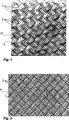
Die Oberflächenstruktur der Scheibe ist hier in Flächenabschnitte bzw. Gruppen
Hieraus ergibt sich optisch der Gesamteindruck eines (in der Zeichnung diagonalen) Schachbrettmusters, oder einer „gewebten” Oberfläche. Es ist zu erwarten, dass im Reflexbild von jedem Betrachtungswinkel aus nur die Hälfte der Gruppen parallel einfallendes (Sonnen-)Licht zum Betrachter hin reflektiert. Dies ergibt sich aus den Orientierungswechseln zwischen den Gruppen.The result is a visual impression of the overall appearance of a (diagonal in the drawing) checkerboard pattern, or a "woven" surface. It is to be expected that in the reflection image from each viewing angle only half of the groups reflect parallel incident (sun) light towards the observer. This results from the orientation changes between the groups.
Man erkennt in der Zeichnung deutlich, dass die Gruppen an allen Seiten von geschwungenen Linien begrenzt sind, zu denen die Seiten der aufgespannten Vierecke die Sehnen bilden. Entlang der Längserstreckung der Elemente
Obwohl in diesen bevorzugten Ausführungsformen gemäß
Denn auch diese Gestaltung der Oberflächenstruktur hat jedenfalls den Vorteil, dass sich keine durchlaufenden geradlinigen Schwachstellen in der Scheibe ausbilden können, da sie in allen Richtungen eine etwa gleichbleibende Biege- bzw. Verformungssteifigkeit aufweist.For even this design of the surface structure in any case has the advantage that no continuous rectilinear weak points in the disc can form, since it has an approximately constant bending or deformation stiffness in all directions.
Die einzelnen Strukturelemente können mit der Scheibendicke skalierende Längen haben. D. h., je dicker die Scheibe, desto größer die möglichen Dimensionen der Breite der Strukturelemente. Dieser Zusammenhang ergibt sich daher, dass die Flankenwinkel vorteilhafterweise mindestens 45 Grad betragen sollten und somit die lateralen Ausmaße die vorteilhafte Mindesttiefe vorgeben. Soll eine „Durchlöcherung” des Substrats vermieden werden, darf die Strukturtiefe – bei eingesenkten Strukturen – natürlich nicht die Scheibendicke überschreiten. Eine Begrenzung der Dimensionierung zu kleinen Werten hin gibt es von theoretischer Seite her nicht. In der Praxis wird die Begrenzung zu kleinen Längen hin durch die technischen Gegebenheiten der Oberflächenformgebung entstehen. Im Falle der Oberflächenformgebung im Walz- oder Gussglasprozess, bei dem bei etwa 1000 Grad mit strukturierten Walzen dem heißen Glas eine Oberflächenstruktur aufgeprägt wird, erscheint die in der Praxis nach derzeitigem Stand der Technik noch sinnvoll umsetzbare kleinste laterale Dimensionierung etwa 1 mm zu sein.The individual structural elements can have scaling lengths with the pane thickness. In other words, the thicker the disk, the larger the possible dimensions of the width of the structural elements. This relationship results from the fact that the flank angle should advantageously be at least 45 degrees and thus specify the lateral dimensions of the advantageous minimum depth. Of course, if a "perforation" of the substrate is to be avoided, the texture depth - in the case of embedded structures - must of course not exceed the thickness of the pane. A limitation of the dimensioning to small values is not there from the theoretical side. In practice, the limitation to small lengths will be due to the technical characteristics of the surface shaping. In the case of surface shaping in the rolled or cast glass process, in which the surface texture of the hot glass is impressed at about 1000 degrees with structured rolls, the smallest lateral dimensioning, which is still feasible in practice according to the current state of the art, appears to be about 1 mm.
Das hier über die lateralen Dimensionen bis hierhin Ausgeführte bezieht sich nur auf die Strukturbreite der einzelnen Strukturelemente, also die Ausdehnung senkrecht zur Längserstreckung der einzelnen Strukturelemente. Die Länge der Längserstreckung sollte klein sein im Verhältnis zu den Gesamtlängen der Seitenkanten der Scheibe, um in alle Richtungen annähernd gleiche mechanische Eigenschaften zu gewährleisten.The here on the lateral dimensions carried out so far refers only to the structural width of the individual structural elements, ie the extension perpendicular to the longitudinal extent of the individual structural elements. The length of the longitudinal extent should be small relative to the total length of the side edges of the disc to ensure nearly equal mechanical properties in all directions.
Die Flankenflächen können aber auch selbst geschwungen ansteigen und abfallen, so dass sich bei in Längserstreckung gekrümmten Strukturelementen sphärisch gekrümmte Flankenflächen ergeben können. Ferner können die Spitzen und Talsohlen abgeflacht bzw. abgerundet sein. In solchen Fällen könnte noch ein mittlerer Flankenwinkel definiert werden, der ebenfalls mindestens 45° betragen soll.However, the flank surfaces can also rise and fall in curves themselves, so that when the structural elements are curved in the longitudinal direction, spherically curved flank surfaces can result. Furthermore, the peaks and bottoms may be flattened or rounded. In such cases, a mean flank angle could be defined, which should also be at least 45 °.
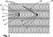
Offensichtlich verändert sich bei einer solchen Oberflächengestaltung der Reflexwinkel von einfallendem Licht entlang jeder Linie sehr rasch in Abhängigkeit vom Betrachtungswinkel, und zwar unabhängig davon, ob das einfallende Licht gestreut (Pfeilgruppe
Eine wesentliche Wirkung auch dieser Anordnung ist eine hohe Steifigkeit der damit ausgestatteten Scheibe in alle Richtungen, insbesondere gegen Biegungen um eine Achse, die sich parallel zum globalen Längsverlauf der Strukturelemente erstreckt. Es gibt nicht wie bei gerade durchlaufenden Strukturelementen geradlinige „Schwachstellen”, die beim Manipulieren der Scheibe – und, wie erwähnt, beim Vorspannen einer entsprechend strukturierten Glasscheibe – zu Wellungen und Bruch führen könnten.An essential effect of this arrangement is a high rigidity of the disk so equipped in all directions, in particular against bends about an axis which extends parallel to the global longitudinal course of the structural elements. There are not straight-line "weak spots", as in the case of straight structural elements, which could lead to corrugations and breakage when manipulating the pane - and, as mentioned, when prestressing a correspondingly structured pane of glass.
Trotzdem erreicht die Oberflächenstruktur eine hohe Ebenmäßigkeit, die je nach Feinheit der Strukturelemente (die beispiels- und vorzugsweise mit Breiten von weniger als einem mm ausgeführt werden) aus größerer Entfernung nicht als Wellenmuster wahrnehmbar ist.Nevertheless, the surface structure achieves a high level of uniformity, which, depending on the fineness of the structural elements (which are, for example, and preferably with widths of less than one mm), can not be perceived as a wave pattern from a greater distance.
Claims (11)
Priority Applications (11)
| Application Number | Priority Date | Filing Date | Title |
|---|---|---|---|
| DE102005027737A DE102005027737B4 (en) | 2005-06-16 | 2005-06-16 | Use of a transparent disc with a three-dimensional surface structure as a cover plate for components for the use of sunlight |
| EP06778928A EP1891468A2 (en) | 2005-06-16 | 2006-06-13 | Glass pane with light-capturing surface structure |
| US11/917,479 US20100051093A1 (en) | 2005-06-16 | 2006-06-13 | Glass pane with light-capturing surface structure |
| MX2007015993A MX2007015993A (en) | 2005-06-16 | 2006-06-13 | Glass pane with light-capturing surface structure. |
| CNA2006800212583A CN101305300A (en) | 2005-06-16 | 2006-06-13 | Glass pane with light-capturing surface structure |
| BRPI0612619-7A BRPI0612619A2 (en) | 2005-06-16 | 2006-06-13 | 'assembly, transparent glass pane, processes for making a pane and for collecting light and transmitting it to a light-collecting element and using a pane |
| JP2008516390A JP2009508147A (en) | 2005-06-16 | 2006-06-13 | Pane with light-trapping surface structure |
| KR1020077028953A KR101500540B1 (en) | 2005-06-16 | 2006-06-13 | Glass pane with light-capturing surface structure |
| PCT/FR2006/050550 WO2006134300A2 (en) | 2005-06-16 | 2006-06-13 | Glass pane with light-capturing surface structure |
| IL188133A IL188133A (en) | 2005-06-16 | 2007-12-13 | Glass pane with light-capturing surface structure |
| JP2014125420A JP2014197219A (en) | 2005-06-16 | 2014-06-18 | Pane with light-trapping surface structure |
Applications Claiming Priority (1)
| Application Number | Priority Date | Filing Date | Title |
|---|---|---|---|
| DE102005027737A DE102005027737B4 (en) | 2005-06-16 | 2005-06-16 | Use of a transparent disc with a three-dimensional surface structure as a cover plate for components for the use of sunlight |
Publications (2)
| Publication Number | Publication Date |
|---|---|
| DE102005027737A1 DE102005027737A1 (en) | 2006-12-21 |
| DE102005027737B4 true DE102005027737B4 (en) | 2013-03-28 |
Family
ID=37111385
Family Applications (1)
| Application Number | Title | Priority Date | Filing Date |
|---|---|---|---|
| DE102005027737A Expired - Fee Related DE102005027737B4 (en) | 2005-06-16 | 2005-06-16 | Use of a transparent disc with a three-dimensional surface structure as a cover plate for components for the use of sunlight |
Country Status (10)
| Country | Link |
|---|---|
| US (1) | US20100051093A1 (en) |
| EP (1) | EP1891468A2 (en) |
| JP (2) | JP2009508147A (en) |
| KR (1) | KR101500540B1 (en) |
| CN (1) | CN101305300A (en) |
| BR (1) | BRPI0612619A2 (en) |
| DE (1) | DE102005027737B4 (en) |
| IL (1) | IL188133A (en) |
| MX (1) | MX2007015993A (en) |
| WO (1) | WO2006134300A2 (en) |
Families Citing this family (25)
| Publication number | Priority date | Publication date | Assignee | Title |
|---|---|---|---|---|
| GB0611747D0 (en) * | 2006-06-14 | 2006-07-26 | Pilkington Plc | Glazing inspection |
| WO2008009428A1 (en) * | 2006-07-20 | 2008-01-24 | Leonhard Kurz Stiftung & Co. Kg | Polymer-based solar cell |
| CN102137819A (en) | 2008-09-01 | 2011-07-27 | 法国圣戈班玻璃厂 | Process for obtaining glass and glass obtained |
| US20110240095A1 (en) * | 2008-11-19 | 2011-10-06 | Toppan Printing Co., Ltd. | Light reuse sheet, solar battery module, and light source module |
| FR2941941B1 (en) | 2009-02-11 | 2011-02-18 | Saint Gobain | FABRICATION OF GLASS FLAT TEXTURE |
| FR2942623B1 (en) | 2009-02-27 | 2012-05-25 | Saint Gobain | GLASS SHEET |
| DE102009016735A1 (en) * | 2009-04-09 | 2010-10-21 | Schott Ag | Photovoltaic modules with reduced weight |
| FR2946335B1 (en) | 2009-06-05 | 2011-09-02 | Saint Gobain | THIN LAYER DEPOSITION METHOD AND PRODUCT OBTAINED |
| FR2948230B1 (en) | 2009-07-16 | 2011-10-21 | Saint Gobain | TEXTURED TRANSPARENT PLATE AND METHOD OF MANUFACTURING SUCH PLATE |
| FR2951157A1 (en) | 2009-10-12 | 2011-04-15 | Saint Gobain | FRITTE DE VERRE |
| FR2955101B1 (en) | 2010-01-11 | 2012-03-23 | Saint Gobain | PHOTOCATALYTIC MATERIAL AND GLAZING OR PHOTOVOLTAIC CELL COMPRISING THIS MATERIAL |
| JP5844798B2 (en) | 2010-04-28 | 2016-01-20 | スリーエム イノベイティブ プロパティズ カンパニー | Articles and methods comprising nanosilica-based primers for polymer coatings |
| CN102918093B (en) | 2010-04-28 | 2017-04-12 | 3M创新有限公司 | Silicone-based material |
| BR112013006753A2 (en) | 2010-10-06 | 2016-06-21 | 3M Innovative Properties Co | anti-reflective articles with nanosilica coatings and barrier layer |
| FR2971519A1 (en) | 2011-02-16 | 2012-08-17 | Saint Gobain | METHOD FOR OBTAINING PHOTOCATALYTIC MATERIAL |
| US9365449B2 (en) | 2011-03-09 | 2016-06-14 | Empire Technology Development Llc | Selective light transmitting window glazings and methods of design and manufacture |
| FR2978772B1 (en) | 2011-08-01 | 2013-08-02 | Saint Gobain | PHOTOBIOREACTOR PROVIDED WITH A SELECTIVE THIN LAYER STACK. |
| FR2979910B1 (en) | 2011-09-13 | 2014-01-03 | Saint Gobain | PHOTOCATALYTIC MATERIAL AND GLAZING OR PHOTOVOLTAIC CELL COMPRISING THIS MATERIAL |
| WO2013056747A1 (en) * | 2011-10-21 | 2013-04-25 | Omt Solutions Beheer B.V. | Transparent optical panel, a solar module, and method of manufacturing the transparent optical panel |
| FR2982257A1 (en) | 2011-11-09 | 2013-05-10 | Saint Gobain | GLASS SHEET |
| US9188723B2 (en) | 2013-03-14 | 2015-11-17 | Ppg Industries Ohio, Inc. | Patterns on glass for increased light transmission and/or light trapping |
| WO2015013475A1 (en) | 2013-07-26 | 2015-01-29 | Corning Incorporated | Corrugated sheet, method of manufacture thereof, and mold therefor |
| BE1021974B1 (en) * | 2013-09-03 | 2016-02-01 | Agc Glass Europe | TEXTURE GLASS SHEET WITH RECTIFIED PATTERNS |
| US10793461B2 (en) * | 2016-11-18 | 2020-10-06 | Corning Incorporated | Method and system for making 3D glass, glass-ceramic and ceramic objects |
| FR3115157A1 (en) * | 2020-10-08 | 2022-04-15 | Saint-Gobain Glass France | TEXTURED GLASS FOR PHOTOVOLTAIC SYSTEMS |
Citations (7)
| Publication number | Priority date | Publication date | Assignee | Title |
|---|---|---|---|---|
| AT47274B (en) * | 1908-05-25 | 1911-04-10 | Otis Angelo Mygatt | Glass envelopes or glass vessels. |
| AT47786B (en) * | 1909-09-27 | 1911-05-10 | Desire Louis Joseph Houvenagel | Glass with prismatic waves for glazing and paving. |
| DE1659950U (en) * | 1953-05-20 | 1953-07-23 | Peill & Putzler Gmbh | GLASS BODY PROFILED ON BOTH SIDES IN THE SHAPE OF A LEVEL OR CURVED PLATE FOR SHIELDING FLUORESCENT LAMPS. |
| US2875543A (en) * | 1957-09-04 | 1959-03-03 | L E Carpenter & Company Inc | Surface ornamentation of flexible sheet materials and method of making tools for producing such ornamentation |
| DE1891408U (en) * | 1963-04-27 | 1964-04-23 | Rupert Nikoll | LIGHT TRANSMISSION PLATE, IN PARTICULAR GLASS PLATE FOR COVERING LIGHTING ELEMENTS. |
| DE29809174U1 (en) * | 1998-02-03 | 1999-06-10 | Lamberts Glasfabrik | Translucent component |
| EP1066445B1 (en) * | 1998-02-03 | 2003-05-21 | GLASFABRIK LAMBERTS GMBH & CO. KG | Transparent building element with triangular ribs |
Family Cites Families (22)
| Publication number | Priority date | Publication date | Assignee | Title |
|---|---|---|---|---|
| US720139A (en) * | 1900-10-18 | 1903-02-10 | Edward Walsh Jr | Curvilinear corrugated prismatic glass. |
| DK79780A (en) * | 1980-02-25 | 1981-08-26 | Elektronikcentralen | Solar cells with a semiconductor crystal and with a lighted surface battery of solar cells and methods for making the same |
| JPS57165801A (en) * | 1981-04-06 | 1982-10-13 | Masayasu Negishi | Removing device for out-of-field surface reflection having less image movement and less color generation |
| JPS63195135A (en) * | 1987-02-09 | 1988-08-12 | Nippon Sheet Glass Co Ltd | Production of figured glass |
| US5193899A (en) * | 1989-04-25 | 1993-03-16 | Mitsubishi Rayon Co., Ltd. | Planar light-source device and illumination apparatus using the same |
| JPH06286395A (en) * | 1993-03-31 | 1994-10-11 | Toppan Printing Co Ltd | Decorative material having see-through and manufacture thereof |
| JPH08204220A (en) * | 1995-01-31 | 1996-08-09 | Mitsubishi Electric Corp | Solar cell, solar cell module and solar cell module group |
| JPH10253773A (en) * | 1997-01-08 | 1998-09-25 | Seiko Epson Corp | Covering member used to cover surface of solar cell and electronic apparatus provided with it as well as watch |
| JPH1111980A (en) * | 1997-06-27 | 1999-01-19 | Asahi Glass Co Ltd | Transparent conductive glass substrate and its production |
| JPH1187744A (en) * | 1997-09-11 | 1999-03-30 | Canon Inc | Manufacture of solar battery module |
| JP4347521B2 (en) * | 1998-02-18 | 2009-10-21 | スリーエム カンパニー | Optical film |
| JP3057438U (en) * | 1998-08-12 | 1999-06-02 | 株式会社トーキン | Light diffusion prism sheet with double structure |
| US6752505B2 (en) * | 1999-02-23 | 2004-06-22 | Solid State Opto Limited | Light redirecting films and film systems |
| JP2001007371A (en) * | 1999-06-17 | 2001-01-12 | Nippon Telegr & Teleph Corp <Ntt> | Solar cell module |
| JP4402224B2 (en) * | 1999-11-11 | 2010-01-20 | 大日本印刷株式会社 | Sheet having a three-dimensional pattern and method for producing the same |
| JP2002081275A (en) * | 2000-09-11 | 2002-03-22 | Sti Japan:Kk | Light distribution control device, blind, partition, curtain, tent and luminaire |
| EP1301443B1 (en) * | 2001-02-15 | 2003-11-26 | Interfloat Corporation | Glass pane |
| FR2832811B1 (en) * | 2001-11-28 | 2004-01-30 | Saint Gobain | TRANSPARENT TEXTURED PLATE WITH HIGH LIGHT TRANSMISSION |
| JP2004311882A (en) * | 2003-04-10 | 2004-11-04 | Canon Inc | Solar battery array and solar power generation system |
| JP2004335563A (en) * | 2003-05-01 | 2004-11-25 | Sekisui Jushi Co Ltd | Solar cell module |
| JP4811628B2 (en) * | 2003-09-05 | 2011-11-09 | 日立化成工業株式会社 | Condensing film and solar cell unit |
| US20060083004A1 (en) * | 2004-10-15 | 2006-04-20 | Eastman Kodak Company | Flat-panel area illumination system |
-
2005
- 2005-06-16 DE DE102005027737A patent/DE102005027737B4/en not_active Expired - Fee Related
-
2006
- 2006-06-13 BR BRPI0612619-7A patent/BRPI0612619A2/en not_active IP Right Cessation
- 2006-06-13 CN CNA2006800212583A patent/CN101305300A/en active Pending
- 2006-06-13 WO PCT/FR2006/050550 patent/WO2006134300A2/en active Search and Examination
- 2006-06-13 EP EP06778928A patent/EP1891468A2/en not_active Withdrawn
- 2006-06-13 JP JP2008516390A patent/JP2009508147A/en not_active Withdrawn
- 2006-06-13 US US11/917,479 patent/US20100051093A1/en not_active Abandoned
- 2006-06-13 MX MX2007015993A patent/MX2007015993A/en active IP Right Grant
- 2006-06-13 KR KR1020077028953A patent/KR101500540B1/en not_active IP Right Cessation
-
2007
- 2007-12-13 IL IL188133A patent/IL188133A/en active IP Right Grant
-
2014
- 2014-06-18 JP JP2014125420A patent/JP2014197219A/en active Pending
Patent Citations (7)
| Publication number | Priority date | Publication date | Assignee | Title |
|---|---|---|---|---|
| AT47274B (en) * | 1908-05-25 | 1911-04-10 | Otis Angelo Mygatt | Glass envelopes or glass vessels. |
| AT47786B (en) * | 1909-09-27 | 1911-05-10 | Desire Louis Joseph Houvenagel | Glass with prismatic waves for glazing and paving. |
| DE1659950U (en) * | 1953-05-20 | 1953-07-23 | Peill & Putzler Gmbh | GLASS BODY PROFILED ON BOTH SIDES IN THE SHAPE OF A LEVEL OR CURVED PLATE FOR SHIELDING FLUORESCENT LAMPS. |
| US2875543A (en) * | 1957-09-04 | 1959-03-03 | L E Carpenter & Company Inc | Surface ornamentation of flexible sheet materials and method of making tools for producing such ornamentation |
| DE1891408U (en) * | 1963-04-27 | 1964-04-23 | Rupert Nikoll | LIGHT TRANSMISSION PLATE, IN PARTICULAR GLASS PLATE FOR COVERING LIGHTING ELEMENTS. |
| DE29809174U1 (en) * | 1998-02-03 | 1999-06-10 | Lamberts Glasfabrik | Translucent component |
| EP1066445B1 (en) * | 1998-02-03 | 2003-05-21 | GLASFABRIK LAMBERTS GMBH & CO. KG | Transparent building element with triangular ribs |
Also Published As
| Publication number | Publication date |
|---|---|
| DE102005027737A1 (en) | 2006-12-21 |
| WO2006134300A3 (en) | 2007-03-29 |
| KR20080017350A (en) | 2008-02-26 |
| KR101500540B1 (en) | 2015-03-09 |
| BRPI0612619A2 (en) | 2012-10-02 |
| CN101305300A (en) | 2008-11-12 |
| MX2007015993A (en) | 2008-03-07 |
| WO2006134300A2 (en) | 2006-12-21 |
| EP1891468A2 (en) | 2008-02-27 |
| US20100051093A1 (en) | 2010-03-04 |
| IL188133A (en) | 2015-09-24 |
| JP2009508147A (en) | 2009-02-26 |
| JP2014197219A (en) | 2014-10-16 |
| IL188133A0 (en) | 2008-03-20 |
Similar Documents
| Publication | Publication Date | Title |
|---|---|---|
| DE102005027737B4 (en) | Use of a transparent disc with a three-dimensional surface structure as a cover plate for components for the use of sunlight | |
| DE102005027799B4 (en) | Method for producing a transparent pane with a surface structure and apparatus for carrying out the method | |
| EP1301443B1 (en) | Glass pane | |
| DE112006003072T5 (en) | A method of structuring a side of a substrate of glass, such substrate, and structuring means for the method | |
| DE4236799A1 (en) | Manufacturing method for triple reflectors and their tools - has strips formed by grinding in different directions, following direction of strip extension during process | |
| DE102006058247A1 (en) | Method and device for producing profiled glass elements and profiled glass element and its use | |
| DE4242264C2 (en) | Body or component with a surface having a microdouble triple and method for producing such a body or component | |
| DE2337214A1 (en) | LIGHT GUIDE DEVICE | |
| DE19622670C2 (en) | Light deflection plate with two flat elements | |
| CH693771A5 (en) | Glass, in particular for use in solar applications. | |
| DE69833627T2 (en) | Glass element for room lighting with daylight | |
| AT520942B1 (en) | Process for producing a light-guiding film and film produced therewith | |
| EP0487997B1 (en) | Louvre blind | |
| WO2011124294A1 (en) | Device for coupling out light in a reduced-glare manner | |
| DE102004043556A1 (en) | Solar collector with translucent cover | |
| DE2826654C2 (en) | False ceiling | |
| DE202005017154U1 (en) | Transparent component made from glass and/or plastic for glazing windows and doors comprises a two- or three-dimensional inner engraving running at a distance to its upper surfaces and produced using a laser beam | |
| AT514578B1 (en) | Cover for a solar module | |
| DE102019006130A1 (en) | LIGHT PROTECTION DEVICE WITH HIGH PRECISION OPTICS FOR GLARE-FREE LIGHT DEFLECTION | |
| DE102009056343A1 (en) | Light guiding slats used for vertical and horizontal light deflection to ceiling of interior room, has line shaped indents which are extended straight or diagonal, perpendicularly and/or inclined relative to slat edges to reflect light | |
| DE1958255A1 (en) | Reflective warning triangle | |
| DE1130334B (en) | Decorative material and tools for its manufacture | |
| DE10346505A1 (en) | Light-permeable pane used in a composite glass pane for doors and for glazing a door filling has upper surfaces provided with a regular three-dimensional pattern which can be visually observed | |
| DE1142324B (en) | For light and heat rays partially permeable plate | |
| DE1065581B (en) | Object made of transparent material, such as panes, paving stones or building blocks made of glass, of variable transparency or color |
Legal Events
| Date | Code | Title | Description |
|---|---|---|---|
| OP8 | Request for examination as to paragraph 44 patent law | ||
| R016 | Response to examination communication | ||
| R016 | Response to examination communication | ||
| R018 | Grant decision by examination section/examining division | ||
| R020 | Patent grant now final |
Effective date: 20130629 |
|
| R119 | Application deemed withdrawn, or ip right lapsed, due to non-payment of renewal fee |