Hintergrund der ErfindungBackground of the invention
Die vorliegende Erfindung bezieht sich auf eine automatische Schaltvorrichtung für das Geschwindigkeitsreduzierverhältnis (Untersetzung), die in der Lage ist, das von einer Ausgangsweile über einen Planetengetriebemechanismus auf ein Verschiebungselement eines Stellgliedes übertragene Untersetzungsverhältnis automatisch zu schalten, wenn eine Last, die ein festgelegtes Drehmoment überschreitet, aufgebracht wird.The present invention relates to an automatic speed reducing ratio (reduction) switching device capable of automatically switching the speed reduction ratio transmitted from an output shaft to a displacement element of an actuator via a planetary gear mechanism when a load exceeding a set torque exceeds a predetermined torque. is applied.
Schaltmechanismen für das Untersetzungsverhältnis werden bisher bspw. in Maschinensystemen, wie Konstruktionsmaschinen eingesetzt. Bei einem solchen Maschinensystem wird ein elektrischer Zylinder als Stellglied für ein Expansions-/Kontraktionsbetriebssystem zum Antreiben eines Verbindungsmechanismus eingesetzt.Switching mechanisms for the reduction ratio have hitherto been used, for example, in machine systems such as construction machines. In such a machine system, an electric cylinder is used as an actuator for an expansion / contraction operating system for driving a link mechanism.
In einem solchen elektrischen Zylinder ist eine Drehwelle mit einem Eingangsabschnitt eines Elektromotors in einem Gehäuse verbunden, und in der Drehwelle ist eine Gewindewelle angeordnet. Die Gewindewelle ist in ein Mutternelement geschraubt, das drehbar in dem Gehäuse gehalten wird. Zwei Paare von Planetengetriebemechanismen mit unterschiedlichen Untersetzungsverhältnissen sind zwischen der Drehwelle und dem Mutternelement vorgesehen. Jedes der Planetengetriebe umfasst ein Sonnenrad und Planetenräder, die mit dem Sonnenrad kämmen, und ein innenverzahntes Rad (Hohlrad), das in dem zylindrischen Gehäuse vorgesehen ist, um die Planetenbewegung durchzuführen. Jedes der Sonnenräder ist mit der Drehwelle über eine Einwegkupplung verbunden, in der die Eingriffsrichtung sich für die Vorwärtsrichtung und die Rückwärtsrichtung unterscheidet. Eine Planetentragwelle, die die Planetenräder jedes der Planetengetriebe drehbar trägt, ist mit dem Mutternelement verbunden.In such an electric cylinder, a rotary shaft is connected to an input portion of an electric motor in a housing, and a threaded shaft is disposed in the rotary shaft. The threaded shaft is screwed into a nut member which is rotatably supported in the housing. Two pairs of planetary gear mechanisms having different reduction ratios are provided between the rotary shaft and the nut member. Each of the planet gears includes a sun gear and planetary gears meshing with the sun gear, and an internal gear (ring gear) provided in the cylindrical housing to perform the planetary motion. Each of the sun gears is connected to the rotary shaft via a one-way clutch in which the engagement direction differs for the forward direction and the reverse direction. A planetary support shaft rotatably supporting the planet gears of each of the planetary gears is connected to the nut member.
Wenn der Elektromotor in Vorwärtsrichtung angetrieben und gedreht wird, dann wird in dem Elektrozylinder auch die Drehwelle in der Vorwärtsrichtung gedreht, das Mutternelement wird mit Hilfe des Planetengetriebes, das ein kleines Untersetzungsverhältnis aufweist, in der Vorwärtsrichtung gedreht, so dass die Gewindewelle in expandierender (ausfahrender) Weise bewegt wird. Wenn andererseits der Elektromotor in der Rückwärtsrichtung angetrieben und gedreht wird, so wird auch die Drehwelle in der Rückwärtsrichtung gedreht, das Mutternelement wird mit Hilfe des Planetengetriebes, das ein großes Untersetzungsverhältnis aufweist, in der Rückwärtsrichtung gedreht, so dass die Gewindewelle in einer kontrahierenden Weise (einfahrend) bewegt wird (vgl. die japanische Offenlegungsschrift JP 2003-184982 A ).When the electric motor is driven and rotated in the forward direction, in the electric cylinder, the rotating shaft is also rotated in the forward direction, the nut member is rotated in the forward direction by means of the planetary gear having a small reduction ratio, so that the screw shaft in expanding (extending ) Way is moved. On the other hand, when the electric motor is driven and rotated in the reverse direction, the rotary shaft is also rotated in the reverse direction, the nut member is rotated in the reverse direction by means of the planetary gear having a large reduction ratio, so that the screw shaft is contracted (FIG. entering) is moved (see Japanese Laid-Open Patent Publication JP 2003-184982 A ).
Bei dem oben beschriebenen elektrischen Zylinder ist es aber notwendig, die beiden Arten von Planetengetriebe mit unterschiedlichen Untersetzungsverhältnissen einzusetzen, damit die Gewindewelle die ausfahrende und die einfahrende Bewegung durchführen kann. Hierdurch wird die Zahl der Teile erhöht, und der gesamte elektrische Zylinder erhält eine große Baugröße. Bei dem Planetengetriebe des oben beschriebenen elektrischen Zylinders wird die ausfahrende Bewegung mit niedriger Geschwindigkeit und hoher Schubkraft durchgeführt, während die einfahrende Bewegung mit hoher Geschwindigkeit und geringer Schubkraft durchgeführt wird, unabhängig von der Größe des Lastdrehmomentes, das auf den elektrischen Zylinder ausgeübt wird. Daher kann die Bewegungsgeschwindigkeit der Gewindewelle für die ausfahrende Bewegung nicht auf eine hohe Geschwindigkeit erhöht werden, auch wenn das auf den elektrischen Zylinder aufgebrachte Lastdrehmoment klein ist.In the electric cylinder described above, however, it is necessary to use the two types of planetary gear with different reduction ratios, so that the threaded shaft can perform the extending and the retracting movement. As a result, the number of parts is increased, and the entire electric cylinder is given a large size. In the planetary gear of the above-described electric cylinder, the low-speed, high-thrust extension movement is performed while the high-speed and low-thrust retracting movement is performed regardless of the magnitude of the load torque applied to the electric cylinder. Therefore, even if the load torque applied to the electric cylinder is small, the traveling speed of the threaded shaft for the extending movement can not be increased to a high speed.
Das Dokument US 3 079 814 A offenbart einen Untersetzungsmechanismus, welcher das übertragene Drehmoment auf einen vorgegebenen Wert begrenzt, wobei der Antrieb sofort wieder aufgenommen wird, sobald das Drehmoment unter diesen Wert fällt.The document US Pat. No. 3,079,814 discloses a reduction mechanism which limits the transmitted torque to a predetermined value, the drive being resumed immediately as soon as the torque falls below this value.
Zusammenfassung der ErfindungSummary of the invention
Es ist daher Aufgabe der vorliegenden Erfindung, eine automatische Untersetzungsverhältnis-Schaltvorrichtung vorzuschlagen, die es ermöglicht, das Drehmoment zu steuern und mit hoher Geschwindigkeit zu übertragen, indem das Untersetzungsverhältnis entsprechend der Betriebsweise eines Verschiebungselementes eines Stellgliedes automatisch gesteuert wird.It is therefore an object of the present invention to provide an automatic reduction ratio switching device which makes it possible to control the torque and transmit at high speed by automatically controlling the reduction ratio according to the operation of a displacement element of an actuator.
Die Zahl der Teile und die Gesamtgröße der Vorrichtung soll erfindungsgemäß verringert werden.The number of parts and the total size of the device should be reduced according to the invention.
Diese Aufgabe wird mit der Erfindung im Wesentlichen durch die Merkmale des Anspruchs 1 gelöst.This object is achieved with the invention essentially by the features of claim 1.
Vorteilhafte Ausgestaltungen der Erfindung ergeben sich aus den Unteransprüchen.Advantageous embodiments of the invention will become apparent from the dependent claims.
Die Erfindung wird nachfolgend anhand von Ausführungsbeispielen und der Zeichnung näher erläutert.The invention will be explained in more detail with reference to embodiments and the drawing.
Kurze Beschreibung der ZeichnungenBrief description of the drawings
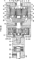
1 ist eine perspektivische Explosionsdarstellung einer automatischen Untersetzungsverhältnis-Schaltvorrichtung gemäß einer ersten Ausführungsform der vorliegenden Erfindung; 1 Fig. 13 is an exploded perspective view of an automatic reduction ratio switching device according to a first embodiment of the present invention;
2 ist ein Längsschnitt in axialer Richtung durch die erste Ausführungsform der vorliegenden Erfindung; 2 Fig. 12 is a longitudinal sectional view in the axial direction of the first embodiment of the present invention;
3A ist ein Längsschnitt in axialer Richtung, wobei ein Planetenrad der automatischen Schaltvorrichtung gemäß 1 dargestellt ist, 3A is a longitudinal section in the axial direction, wherein a planetary gear of the automatic switching device according to 1 is shown
3B ist ein Schnitt entlang der Linie IIIB-IIIB in 3A; 3B is a section along the line IIIB-IIIB in 3A ;
4 ist ein vergrößerter Teilschnitt, der einen Kämmungsbereich zwischen dem Planetenrad und einem innenverzahnten Rad darstellt; 4 is an enlarged partial section illustrating a meshing area between the planetary gear and an internally toothed wheel;
5 ist eine teilweise aufgebrochene perspektivische Ansicht einer automatischen Untersetzungsverhältnis-Schaltvorrichtung gemäß der ersten Ausführungsform der vorliegenden Erfindung; 5 Fig. 10 is a partially broken perspective view of an automatic reduction ratio switching device according to the first embodiment of the present invention;
6 ist eine Seitenansicht eines Sonnenrades, der Planetenräder und des innenverzahnten Rades in einem Zustand hoher Rotationsgeschwindigkeit; 6 Fig. 12 is a side view of a sun gear, planetary gears and internal gear in a high rotational speed state;
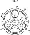
7 ist eine Seitenansicht des Sonnenrades, der Planetenräder und des innenverzahnten Rades, wenn eine Last, die ein eingestelltes Drehmoment überschreitet, auf einen Träger aufgebracht wird; 7 Fig. 12 is a side view of the sun gear, the planetary gears and the internal gear when a load exceeding a set torque is applied to a carrier;
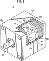
8 ist eine teilweise aufgebrochene perspektivische Ansicht, die einen verriegelten Zustand der automatischen Schaltvorrichtung gemäß der ersten Ausführungsform der vorliegenden Erfindung darstellt; 8th Fig. 10 is a partially broken perspective view illustrating a locked state of the automatic switching device according to the first embodiment of the present invention;
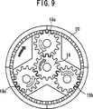
9 ist eine Seitenansicht des Sonnenrades, der Planetenräder und des Innenverzahnten Rades in dem oben beschriebenen verriegelten Zustand; 9 Fig. 12 is a side view of the sun gear, the planet gears and the internal gear in the locked state described above;
10 ist eine Seitenansicht des Sonnenrades, der Planetenräder und des innenverzahnten Rades unmittelbar nach Umkehrung der Drehrichtung des Sonnenrades; 10 is a side view of the sun gear, the planetary gears and the internal gear immediately after reversal of the direction of rotation of the sun gear;
11 ist eine Seitenansicht des Sonnenrades, der Planetenräder und des innenverzahnten Rades in einem Zustand, in dem die Drehrichtung des Sonnenrades umgekehrt ist und dieses mit hoher Geschwindigkeit gedreht wird; 11 is a side view of the sun gear, the planetary gears and the internal gear in a state in which the direction of rotation of the sun gear is reversed and this is rotated at high speed;
12 ist eine teilweise aufgebrochene perspektivische Ansicht, die den verriegelten Zustand der automatischen Schaltvorrichtung gemäß der ersten Ausführungsform der vorliegenden Erfindung darstellt; 12 Fig. 16 is a partially broken perspective view illustrating the locked state of the automatic switching device according to the first embodiment of the present invention;
13 ist eine Seitenansicht, die die Drehrichtungen des Sonnenrades, der Planetenräder und des innenverzahnten Rades in einem Zustand darstellt, in dem die Last auf die Abtriebswelle gegenüber der in 8 reduziert ist; 13 is a side view illustrating the directions of rotation of the sun gear, the planet gears and the internal gear in a state in which the load on the output shaft relative to the in 8th is reduced;
14 ist eine vergrößerte Teilansicht, die einen Bereich darstellt, in dem eine Innenverzahnungskupplung und ein Verriegelungsabschnitt mit Bezug auf 8 in Eingriff miteinander stehen; 14 FIG. 15 is a partial enlarged view illustrating a portion in which an internal gear coupling and a locking portion with respect to 8th engage with each other;
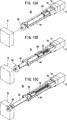
15A ist eine perspektivische Ansicht, die einen Zustand darstellt, in dem ein Verschiebungselement eines Stellgliedes an der Ursprungsposition angeordnet ist; 15A is a perspective view illustrating a state in which a displacement element of an actuator is arranged at the original position;
15B ist eine perspektivische Ansicht, die einen Zustand darstellt, in dem das Verschiebungselement des Stellgliedes zu einem Werkstück hin verschoben ist; 15B Fig. 15 is a perspective view illustrating a state in which the displacement member of the actuator is shifted toward a workpiece;
15C ist eine perspektivische Ansicht, die einen Zustand darstellt, in dem das Verschiebungselement des Stellgliedes an dem Werkstück anliegt; 15C is a perspective view illustrating a state in which the displacement element of the actuator abuts against the workpiece;
16 ist ein Längsschnitt, der einen Zustand darstellt, in dem ein bewegliches Element unter Verwendung eines Riemens verschoben wird; 16 Fig. 15 is a longitudinal sectional view illustrating a state in which a movable member is shifted by using a belt;
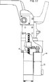
17 ist eine teilweise aufgebrochene Seitenansicht einer elektrischen Klemmvorrichtung; 17 is a partially broken side view of an electrical clamping device;
18 ist ein Längsschnitt in axialer Richtung durch die elektrische Klemmvorrichtung; 18 is a longitudinal section in the axial direction by the electrical clamping device;
19 ist eine teilweise weggeschnittene Seitenansicht, die einen Zustand darstellt, in dem ein hydraulischer Zylinder benachbart angeordnet ist; 19 Fig. 13 is a partially cutaway side view illustrating a state in which a hydraulic cylinder is disposed adjacent;
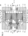
20 ist ein Längsschnitt, der einen viskosen Kupplungsabschnitt für die automatische Untersetzungsverhältnis-Schaltvorrichtung gemäß 1 gemäß einer zweiten Ausführungsform der vorliegenden Erfindung darstellt; 20 FIG. 15 is a longitudinal sectional view illustrating a viscous coupling portion for the automatic reduction ratio switching device according to FIG 1 according to a second embodiment of the present invention;
21 ist ein Längsschnitt durch eine modifizierte Ausführungsform der automatischen Untersetzungsverhältnis-Schaltvorrichtung gemäß 20; 21 is a longitudinal section through a modified embodiment of the automatic reduction ratio switching device according to 20 ;
22A–D sind jeweilige Längsschnitte, die Zustände darstellen, in denen verschiedene Mechanismen zwischen der Antriebswelle und der Abtriebswelle in der automatischen Untersetzungsverhältnis-Schaltvorrichtung gemäß 1 vorgesehen sind; 22A -D are respective longitudinal sections illustrating states in which various mechanisms between the drive shaft and the output shaft in the automatic reduction ratio switching device according to 1 are provided;
23 ist ein Längsschnitt durch eine automatische Untersetzungsverhältnis-Schaltvorrichtung gemäß einer dritten Ausführungsform der vorliegenden Erfindung; 23 Fig. 15 is a longitudinal sectional view of an automatic reduction ratio switching device according to a third embodiment of the present invention;
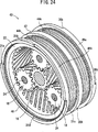
24 ist eine perspektivische Ansicht eines Inneverzahnungs-Verriegelungsfreigabemechanismus; 24 Fig. 13 is a perspective view of an internal tooth locking release mechanism;
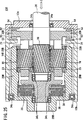
25 ist ein Längsschnitt durch eine automatische Untersetzungsverhältnis-Schaltvorrichtung gemäß einer vierten Ausführungsform der vorliegenden Erfindung; 25 Fig. 15 is a longitudinal sectional view of an automatic reduction ratio switching device according to a fourth embodiment of the present invention;
26 ist ein Längsschnitt durch eine automatische Untersetzungsverhältnis-Schaltvorrichtung gemäß einer fünften Ausführungsform der vorliegenden Erfindung; 26 Fig. 15 is a longitudinal sectional view of an automatic reduction ratio switching device according to a fifth embodiment of the present invention;
27 ist eine perspektivische Explosionsdarstellung einer automatischen Untersetzungsverhältnis-Schaltvorrichtung gemäß einer sechsten Ausführungsform der vorliegenden Erfindung; 27 Fig. 13 is an exploded perspective view of an automatic reduction ratio switching device according to a sixth embodiment of the present invention;
28 ist ein Längsschnitt durch die automatische Untersetzungsverhältnis-Schaltvorrichtung gemäß der sechsten Ausführungsform der vorliegenden Erfindung; 28 Fig. 15 is a longitudinal sectional view of the automatic reduction ratio switching device according to the sixth embodiment of the present invention;
29A ist ein vergrößerter Teilschnitt, der einen Zustand darstellt, in dem ein innenverzahntes Rad durch einen Befestigungsmechanismus gehalten wird; 29A Fig. 15 is an enlarged fragmentary sectional view illustrating a state in which an internal gear is held by a fixing mechanism;
29B + C sind jeweilige vergrößerte Teilschnitte, die Zustände darstellen, in denen das innenverzahnte Rad von dem Befestigungsmechanismus freigegeben wird und horizontal in der Richtung zu der Abtriebswelle oder in der Richtung zu der Antriebswelle bewegt ist; 29B + C are respective enlarged partial sectional views illustrating states in which the internal gear is released from the fixing mechanism and moved horizontally in the direction toward the output shaft or in the direction toward the drive shaft;
30 ist ein Längsschnitt durch eine automatische Untersetzungsverhältnis-Schaltvorrichtung gemäß einer siebten Ausführungsform der vorliegenden Erfindung; 30 Fig. 15 is a longitudinal sectional view of an automatic reduction ratio switching device according to a seventh embodiment of the present invention;
31 ist eine perspektivische Ansicht einer Verriegelungsplatte mit dem Dämpfungsvorsprung; 31 is a perspective view of a locking plate with the damping projection;
32 ist ein vergrößerter Teilschnitt durch einen Dämpfungsmechanismus; 32 is an enlarged partial section through a damping mechanism;
33 ist ein Längsschnitt, der einen Zustand darstellt, in dem eine automatische Untersetzungseinheit und eine Untersetzungseinheit mit festem Untersetzungsverhältnis miteinander gekoppelt sind; 33 Fig. 15 is a longitudinal sectional view illustrating a state in which an automatic reduction unit and a fixed reduction ratio reduction unit are coupled with each other;
34 ist ein Klemmmechanismus, bei dem die automatische Untersetzungsverhältnis-Schaltvorrichtung gemäß der ersten Ausführungsform der vorliegenden Erfindung angewendet wird; und 34 FIG. 10 is a clamp mechanism to which the automatic speed-reduction ratio switching apparatus according to the first embodiment of the present invention is applied; FIG. and
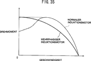
35 ist eine Ansicht, die die Beziehung zwischen der Geschwindigkeit und dem Drehmoment für einen normalen Induktionsmotor und einen Polyphaseninduktionsmotor darstellt. 35 FIG. 14 is a view illustrating the relationship between the speed and the torque for a normal induction motor and a polyphase induction motor.
Beschreibung der bevorzugten AusführungsformenDescription of the Preferred Embodiments
1 zeigt eine perspektivische Explosionsdarstellung einer automatischen Untersetzungsverhältnis-Schaltvorrichtung gemäß einer ersten Ausführungsform der vorliegenden Erfindung. Wie in 1 dargestellt ist, umfasst die automatische Untersetzungsverhältnis-Schaltvorrichtung 10 Gehäuse 12a, 12b, die durch Teilen eines Gehäuses in zwei Teile gebildet werden, und einen Planetengetriebemechanismus 14. 1 shows an exploded perspective view of an automatic reduction ratio switching device according to a first embodiment of the present invention. As in 1 is shown, the automatic reduction ratio switching device comprises 10 casing 12a . 12b , which are formed by dividing a housing into two parts, and a planetary gear mechanism 14 ,
Das Gehäuse 12a ist im Querschnitt rechteckig. An einer Innenseite des Gehäuses 12a sind Verriegelungsabschnitte 32a bis 32d ausgebildet, die kreisbogenförmiger Vorsprünge sind für den Eingriff mit Verriegelungsaufnahmeabschnitten 30a bis 30d eines innenverzahnten Rades, wenn ein innenverzahntes Rad 20 eine Parallelverschiebung in einer Richtung zu einer Eingangs- oder Antriebswelle 26 durchführt (wird später beschrieben). Außerdem weist das Gehäuse 12a einen Lagerabschnitt 34a zum drehbaren Halten der Antriebswelle 26 auf. Das Gehäuse 12b ist in der gleichen Weise wie das Gehäuse 12a im Querschnitt rechteckig. An einer Innenseite des Gehäuses 12b sind Verriegelungsabschnitte 33a bis 33d ausgebildet, die kreisbogenförmige Vorsprünge sind für den Eingriff mit Verriegelungsaufnahmeabschnitten 31a bis 31d eines innenverzahnten Rades 20, wenn das innenverzahnte Rad 20 eine Parallelverschiebung in einer Richtung zu einer Ausgangs- oder Abtriebswelle 28 durchführt (wird später beschrieben). Außerdem weist das Gehäuse 12b einen Lagerabschnitt 34b zum drehbaren Halten der Abtriebswelle 28 auf.The housing 12a is rectangular in cross-section. On an inside of the case 12a are locking sections 32a to 32d formed, the circular arc-shaped projections are for engagement with locking receiving portions 30a to 30d an internally toothed wheel, when an internally toothed wheel 20 a parallel displacement in one direction to an input or drive shaft 26 performs (will be described later). In addition, the housing has 12a a storage section 34a for rotatably holding the drive shaft 26 on. The housing 12b is in the same way as the case 12a rectangular in cross-section. On an inside of the case 12b are locking sections 33a to 33d formed, the circular arc-shaped projections are for engagement with locking receiving portions 31a to 31d an internally toothed wheel 20 when the internal gear wheel 20 a parallel shift in one direction to an output or output shaft 28 performs (will be described later). In addition, the housing has 12b a storage section 34b for rotatably holding the output shaft 28 on.
Das Planetengetriebe 14 umfasst ein Sonnenrad 16, das integral mit der Antriebswelle 26 ausgebildet ist, Planetenräder 18a, 18b, 18c, die mit dem Sonnenrad 16 kämmen, wobei sie voneinander um Winkel von etwa 120° in Umfangsrichtung des Sonnenrades 16 entfernt sind und eine revolvierende (kreisend umlaufende) und rotierende Bewegung durchführen, das innenverzahnte Rad (Hohlrad) 20 und einen Träger 22. Der Träger 22 hat einen zylindrischen inneren Abschnitt 23 mit großem Durchmesser und die Abtriebswelle 28, die von dem inneren Abschnitt 23 vorsteht, wobei sie zu dem Gehäuse 12b gerichtet ist. Das Sonnenrad 16 ist in den inneren Abschnitt 23 eingesetzt, wobei sie dessen Innerem zugewandt ist. Fenster 21, die voneinander einen Abstand von jeweils 120° aufweisen, sind an dem inneren Abschnitt 23 ausgebildet. Die Planetenräder 18a, 18b, 18c sind den Fenstern 21 zugewandt. Bei dieser Ausführungsform werden die Planetenräder 18a, 18b, 18c von dem Träger 22 mit Hilfe von Stiften 24 drehbar gehalten. Wie in den 3A und 3B dargestellt ist, weist jeder Stift 24 Ausschnitte 29a, 29b auf, die durch Wegschneiden von Teilen seiner äußeren Umfangsfläche gebildet werden. Freiräume 25a, 25b werden durch die Ausschnitte 29a, 29b zwischen den Planetenrädern 18a, 18b, 18c und jedem Stift 24 gebildet. Die Freiräume 25a, 25b werden bspw. mit Öl oder Schmierfett gefüllt. Vorzugsweise ist die Qualität der Viskosität des Öles oder Schmierfettes hoch. Das innenverzahnte Rad 20 mit großem Durchmesser kämmt mit den äußeren Umfangsseiten der Planetenräder 18a, 18b, 18c, die mit einer Innenverzahnung kämmen, die in den Innenumfang des Hohlrades 20 eingraviert ist. Das innenverzahnte Hohlrad 20 wird nachfolgend kurz auch als ”Innenverzahnung 20” bezeichnet. Die Antriebswelle 26, die integral mit dem Sonnenrad 16 ausgebildet ist, ist mit einer Drehantriebswelle einer nicht dargestellten Drehantriebsquelle über ein Kupplungselement (nicht dargestellt) verbunden. Bei dieser Anordnung sind die Antriebswelle 26 und die Abtriebswelle 18 koaxial vorgesehen, wie es in 1 dargestellt ist.The planetary gear 14 includes a sun wheel 16 that is integral with the drive shaft 26 is formed planetary gears 18a . 18b . 18c that with the sun wheel 16 combing each other by angles of about 120 ° in the circumferential direction of the sun gear 16 are removed and perform a revolving (circular rotating) and rotating movement, the internal gear (ring gear) 20 and a carrier 22 , The carrier 22 has a cylindrical inner section 23 with large diameter and the output shaft 28 coming from the inner section 23 protruding, leading to the housing 12b is directed. The sun wheel 16 is in the inner section 23 used, wherein it faces its interior. window 21 which are 120 ° apart from each other are at the inner portion 23 educated. The planet wheels 18a . 18b . 18c are the windows 21 facing. In this embodiment, the planet gears 18a . 18b . 18c from the carrier 22 with the help of pins 24 rotatably held. As in the 3A and 3B is shown, each pin has 24 cutouts 29a . 29b which are formed by cutting away parts of its outer peripheral surface. Free rooms 25a . 25b be through the cutouts 29a . 29b between the planet wheels 18a . 18b . 18c and every pen 24 educated. The open spaces 25a . 25b be filled with oil or grease, for example. Preferably, the quality of the viscosity of the oil or grease is high. The internally toothed wheel 20 with a large diameter meshes with the outer peripheral sides of the planetary gears 18a . 18b . 18c , which mesh with an internal toothing, in the inner circumference of the ring gear 20 engraved. The internally toothed ring gear 20 will be briefly referred to as "internal teeth 20 " designated. The drive shaft 26 that is integral with the sun gear 16 is formed, is connected to a rotary drive shaft of a rotary drive source, not shown via a coupling element (not shown). In this arrangement, the drive shaft 26 and the output shaft 18 provided coaxially, as it is in 1 is shown.
Das Sonnenrad 16, die Planetenräder 18a, 18b, 18c und das innenverzahnte Rad 20 weisen eine Schräg- oder Schraubenverzahnung auf. Bei dieser Ausführungsform wird bspw. Öl oder Schmierfett mit hoher Viskosität eingefüllt oder in die Lücken zwischen den Planetenrädern 18a, 18b, 18c und dem inneren Abschnitt 23 des Trägers 22 und zwischen den Planetenrädern 18a, 18b, 18c und dem innenverzahnten Rad 20 eingebracht, um einen viskosen Widerstand zu erreichen. Um den viskosen Widerstand wirksam zu erreichen, wird bevorzugt, dass der Freiraum 27 zwischen dem inneren Abschnitt 23 und der Zahnkante der Innenverzahnung 20 nicht mehr als 0,1 mm beträgt (vgl. 4).The sun wheel 16 , the planetary gears 18a . 18b . 18c and the internally toothed wheel 20 have a helical or helical teeth. In this embodiment, for example, oil or grease is filled with high viscosity or in the gaps between the planetary gears 18a . 18b . 18c and the inner section 23 of the carrier 22 and between the planet wheels 18a . 18b . 18c and the internal gear 20 introduced to achieve a viscous resistance. In order to effectively achieve the viscous resistance, it is preferred that the clearance 27 between the inner section 23 and the tooth edge of the internal toothing 20 is not more than 0.1 mm (cf. 4 ).
Der Torsionswinkel der Schrägverzahnungen zur Bildung des Sonnenrades 16, der Planetenräder 18 und der Innenverzahnung 20 ist nicht eingeschränkt. Vorzugsweise beträgt der Torsionswinkel aber etwa 30° bis 40°. Die Viskosität des Öles, Schmierfettes oder dgl., das als viskoses Widerstandselement eingesetzt wird, ist nicht begrenzt. Vorzugsweise liegt die Viskosität jedoch bei etwa 10.000 bis 100.000 (cSt). Außerdem kann der viskose Widerstand des viskosen Widerstandselementes auch durch die Scherrate oder durch die Breite des Freiraumes und die Viskosität des Schmierfettes oder dgl. geändert werden.The torsion angle of the helical gears to form the sun gear 16 , the planet wheels 18 and the internal teeth 20 is not limited. Preferably, however, the torsion angle is about 30 ° to 40 °. The viscosity of the oil, grease or the like used as the viscous resistive element is not limited. Preferably, however, the viscosity is about 10,000 to 100,000 (cSt). In addition, the viscous resistance of the viscous resistance element can also be changed by the shear rate or by the width of the clearance and the viscosity of the grease or the like.
Eine Mehrzahl von Innenverzahnungsverriegelungsaufnahmeabschnitten 30a bis 30d, 31a bis 31d, die in gekrümmter Weise vorstehen, sind an Enden der zylindrischen Gestalt der Innenverzahnung 20 ausgebildet. Wie in 14 dargestellt ist, haben die Innenverzahnungsverriegelungsaufnahmeabschnitte 30a bis 30d, 31a bis 31d vorspringende Formen, die Kurven in Umfangsrichtung darstellen, entsprechend den Verriegelungsabschnitten 32a bis 32d, 33a bis 33d. Die Innenverzahnungsverriegelungsaufnahmeabschnitte 30a bis 30d, 31a bis 31d und die Verriegelungsabschnitte 32a bis 32d, 33a bis 33d dienen als Innenverzahnungsverriegelungsmechanismus.A plurality of internal gear lock receiving portions 30a to 30d . 31a to 31d which project in a curved manner are at ends of the cylindrical shape of the internal teeth 20 educated. As in 14 2, the inner teeth lock receiving portions have 30a to 30d . 31a to 31d projecting shapes representing curves in the circumferential direction corresponding to the locking portions 32a to 32d . 33a to 33d , The internal gear lock receiving portions 30a to 30d . 31a to 31d and the locking portions 32a to 32d . 33a to 33d serve as an internal gear locking mechanism.
Wenn die Antriebswelle 26, die Innenverzahnung 20 und der Träger 22, die wie oben beschrieben aufgebaut sind, zusammengesetzt werden, wird zunächst die Antriebswelle 26 in den Lagerabschnitt 34a des Gehäuses 12a eingesetzt, die Abtriebswelle 28 wird in den Lagerabschnitt 34b des Gehäuses 12b eingesetzt und die Innenverzahnung 20 wird auf die Außenseite des Trägers 22 aufgesetzt. Das Gehäuse 12a und das Gehäuse 12b werden miteinander so verbunden, dass das Sonnenrad 16 der Antriebswelle 26 mit den Planetenrädern 18a, 18b, 18c kämmt, und dann verschraubt. Dementsprechend ist der Planetengetriebemechanismus 14 in den Gehäusen 12a, 12b aufgenommen (vgl. 5).When the drive shaft 26 , the internal teeth 20 and the carrier 22 , which are constructed as described above, are assembled, first, the drive shaft 26 in the storage section 34a of the housing 12a used, the output shaft 28 gets into the storage section 34b of the housing 12b used and the internal teeth 20 is on the outside of the carrier 22 placed. The housing 12a and the case 12b are connected to each other so that the sun gear 16 the drive shaft 26 with the planet wheels 18a . 18b . 18c combs, and then bolted. Accordingly, the planetary gear mechanism 14 in the cases 12a . 12b recorded (cf. 5 ).
Als nächstes wird die Betriebsweise der automatischen Untersetzungsverhältnis-Schaltvorrichtung 10 erläutert. Zunächst wird die nicht dargestellte Drehantriebsquelle betrieben und die Drehantriebskraft der Drehantriebsquelle über die Antriebswelle 26 auf das Sonnenrad 16 übertragen. Es wird angenommen, dass die Drehantriebskraft die Antriebswelle 26 und das Sonnenrad 16 im Uhrzeigersinn dreht, gesehen in der Richtung von der Antriebswelle 26 zu der Abtriebswelle 28 (Richtung des Pfeils Z in 2).Next, the operation of the automatic reduction ratio switching device will be described 10 explained. First, the unillustrated rotary drive source is operated and the rotational drive force of the rotary drive source via the drive shaft 26 on the sun wheel 16 transfer. It is assumed that the rotational drive force is the drive shaft 26 and the sun wheel 16 Turning clockwise, seen in the direction of the drive shaft 26 to the output shaft 28 (Direction of the arrow Z in 2 ).
Wenn die Rotationskraft mit niedriger Last auf die Antriebswelle 26 übertragen wird, kreisen (laufen um) die Planetenräder 18a, 18b, 18c in Richtung des kreuzschraffierten Pfeils in 6 (und anderen Figuren) ohne (um ihre Achse) zu rotieren, die Innenverzahnung 20 kreist ebenfalls in Richtung des unschraffierten Pfeils in 6 (und anderen Figuren), und der Träger 22 kreist ebenfalls in integrierter Weise im Uhrzeigersinn (vgl. 6), weil das viskose Widerstandselement an dem Sonnenrad 16, den Planetenrädern 18a, 18b, 18c, dem inneren Abschnitt 23 und der Innenverzahnung 20 wirkt und dadurch die statische Reibungskraft durch den viskosen Widerstand des viskosen Widerstandselementes ausgeübt wird. Dies bedeutet mit Bezug auf 6 (und andere Figuren), dass, wenn das Sonnenrad 16 in Richtung des einfach schraffierten Pfeils gedreht wird, die statische Reibungskraft durch das viskose Widerstandselement zwischen dem inneren Abschnitt 23 und der Innenverzahnung 20 aufgrund der geringen Rotation ausgeübt wird. Dementsprechend werden der innere Abschnitt 23, die Innenverzahnung 20, die Planetenräder 18a, 18b, 18c und das Sonnenrad 16 in integrierter Weise gedreht.When the rotational force with low load on the drive shaft 26 is transmitted, revolve (revolve) the planetary gears 18a . 18b . 18c in the direction of the crosshatched arrow in 6 (and other figures) without (about their axis) to rotate, the internal teeth 20 also circles in the direction of the unshaded arrow in 6 (and other figures), and the carrier 22 also circles in an integrated manner in a clockwise direction (cf. 6 ), because the viscous resistance element on the sun gear 16 , the planet wheels 18a . 18b . 18c , the inner section 23 and the internal teeth 20 acts and thereby the static frictional force is exerted by the viscous resistance of the viscous resistance element. This means with reference to 6 (and other figures) that when the sun gear 16 is rotated in the direction of the single-hatched arrow, the static frictional force through the viscous resistance element between the inner portion 23 and the internal teeth 20 due to the low rotation is exercised. Accordingly, the inner section 23 , the internal teeth 20 , the planetary gears 18a . 18b . 18c and the sun wheel 16 rotated in an integrated way.
Wenn anschließend die Last, die ein eingestelltes Drehmoment überschreitet, über die Abtriebswelle 28 auf den Träger 22 aufgebracht wird, so wird das Sonnenrad 16 gedreht, die Planetenräder 18 kreisen nicht (laufen nicht um), sondern rotieren dadurch entgegen dem Uhrzeigersinn (Richtung des unschraffierten Pfeils) entgegen der Richtung des Sonnenrades 16, und die Innenverzahnung 20, die mit den Planetenrädern 18 kämmt, wird entgegen dem Uhrzeigersinn gedreht (vgl. 7). Dies bedeutet, dass wenn die Rotationsgeschwindigkeit durch die auf die Abtriebswelle 28 aufgebrachte Last verringert wird, die Rotationsgeschwindigkeit des Trägers 22, der integral mit der Abtriebswelle 28 ausgebildet ist, ebenfalls abgesenkt wird. Die Innenverzahnung 20 rotiert aber immer noch in der gleichen Weise. Mit anderen Worten ist die Rotationsgeschwindigkeit der Innenverzahnung 20 nicht größer als die Rotationsgeschwindigkeit des Trägers 22. Dadurch wird der viskose Widerstand zwischen der Innenverzahnung 20 und dem Träger 22 erhöht. Wenn der viskose Widerstand in der oben beschriebenen Weise erhöht wird, wird die Schubkraft in Richtung der Verzahnungsstreifen erzeugt, und die Innenverzahnung 20 wird in Richtung des Pfeils Z1 bewegt (vgl. 8), weil die Planetenräder 18a, 18b, 18c und die damit kämmende Innenverzahnung 20 schrägverzahnt sind.Then, when the load exceeding a set torque passes through the output shaft 28 on the carrier 22 is applied, this is how the sun wheel becomes 16 turned, the planetary gears 18 do not rotate (do not turn around), but rotate counterclockwise (direction of the unshaded arrow) against the direction of the sun gear 16 , and the internal teeth 20 that with the planet wheels 18 meshes, is rotated counterclockwise (see. 7 ). This means that when the rotational speed through the on the output shaft 28 applied load is reduced, the rotational speed of the carrier 22 that is integral with the output shaft 28 is formed, is also lowered. The internal toothing 20 but still rotates in the same way. In other words, the rotational speed of the internal teeth 20 not greater than the rotation speed of the carrier 22 , This will cause the viscous resistance between the internal teeth 20 and the carrier 22 elevated. When the viscous resistance is increased in the manner described above, the thrust force is generated in the direction of the spline strips, and the internal teeth 20 is moved in the direction of the arrow Z1 (cf. 8th ), because the planetary gears 18a . 18b . 18c and the internal meshing meshing therewith 20 helical teeth.
Als Folge hiervon greift der Innenverzahnungsverriegelungsaufnahmeabschnitt 31b in den Verriegelungsabschnitt 33b und der Innenverzahnungsverriegelungsabschnitt 31c greift in den Verriegelungsabschnitt 33c. Die Innenverzahnung 20 ist in dem verriegelten Zustand, so dass jegliche weitere Bewegung unmöglich wird. Wenn die Innenverzahnung 20 in dem verriegelten Zustand ist, rotiert das Sonnenrad 16 in Richtung des einfach schraffierten Pfeils in 6, so dass die Planetenräder 18a, 18b, 18c zusammen mit dem Träger 22 umlaufen (vgl. 9), während sie entgegen dem Uhrzeigersinn rotieren, um die abgebremste Rotationsgeschwindigkeit und das erhöhte Drehmoment auf die Abtriebswelle 28 zu übertragen. In dieser Situation besteht das Drehmoment in der Kraft entsprechend dem Übersetzungsverhältnis zwischen den Planetenrädern 18a, 18b, 18c und der Innenverzahnung 20.As a result, the internal gear lock receiving portion engages 31b in the locking section 33b and the internal gear locking portion 31c engages in the locking section 33c , The internal toothing 20 is in the locked state so that any further movement becomes impossible. If the internal teeth 20 in the locked state, the sun gear rotates 16 in the direction of the simply hatched arrow in 6 so that the planetary gears 18a . 18b . 18c together with the carrier 22 to circulate (cf. 9 while rotating counterclockwise to the decelerated rotational speed and the increased torque on the output shaft 28 transferred to. In this situation, the torque is in the force corresponding to the gear ratio between the planetary gears 18a . 18b . 18c and the internal teeth 20 ,
Anschließend wird die Drehantriebsrichtung umgekehrt, um die Innenverzahnung 20 aus dem versiegelten Zustand freizugeben. Dies bedeutet, dass das Sonnenrad 16 mit Hilfe der Antriebswelle 26 in Richtung des Uhrzeigersinns gedreht wird. Als Folge hiervon kreisen die Planetenräder 18a, 18b, 18c zusammen mit dem Träger 22 entgegen dem Uhrzeigersinn (vgl. 10), während sie entsprechend der Rotation des Sonnenrades 16 im Uhrzeigersinn rotieren (vgl. 10). Die Innenverzahnung 20 ist in dem verriegelten Zustand, d. h. in dem angehaltenen Zustand unmittelbar nachdem das Sonnenrad 16 beginnt, sich entgegen dem Uhrzeigersinn zu drehen. Daher tritt ein Unterschied in der Zahl von Relativdrehungen zwischen dem Träger 22 und der Innenverzahnung 20 auf, so dass der viskose Widerstand zwischen der Innenverzahnung 20 und dem inneren Abschnitt 23 erhöht wird. Da der viskose Widerstand zwischen der Innenverzahnung 20 und dem inneren Abschnitt 23 erhöht wird, und da außerdem die Planetenräder 18a, 18b, 18c und die Innenverzahnung 20 Schrägverzahnungen sind, wird eine Schubkraft in Richtung der Verzahnungsstreifen, die schraubenförmig auf den zylindrischen Oberflächen der Zahnräder ausgebildet sind, erzeugt. Die Schubkraft bewirkt, dass die Innenverzahnung 20 eine Parallelverschiebung in Richtung entgegen der Z1-Richtung vollzieht. Die Innenverzahnung 20 vollzieht die Parallelverschiebung in der Richtung entgegen der Z1-Richtung, während sie im Uhrzeigersinn rotiert, die Innenverzahnungsverriegelungsaufnahmeabschnitte 30 der Innenverzahnung 20 werden von den Verriegelungsabschnitten 32 des Gehäuses 12b getrennt und die Innenverzahnung 20 wird aus dem verriegelten Zustand freigegeben.Subsequently, the rotational drive direction is reversed to the internal teeth 20 released from the sealed state. This means that the sun gear 16 with the help of the drive shaft 26 is rotated in the clockwise direction. As a result, the planetary gears revolve 18a . 18b . 18c together with the carrier 22 in the counterclockwise direction (cf. 10 ) while according to the rotation of the sun gear 16 rotate clockwise (cf. 10 ). The internal toothing 20 is in the locked state, that is, in the stopped state immediately after the sun gear 16 starts to turn counterclockwise. Therefore, a difference occurs in the number of relative rotations between the carrier 22 and the internal teeth 20 on, allowing the viscous resistance between the internal teeth 20 and the inner section 23 is increased. Because the viscous resistance between the internal teeth 20 and the inner section 23 is increased, and there also the planetary gears 18a . 18b . 18c and the internal teeth 20 Be helical gears, a thrust force is generated in the direction of the toothed strips, which are helically formed on the cylindrical surfaces of the gears. The thrust force causes the internal teeth 20 performs a parallel shift in the direction opposite to the Z1 direction. The internal toothing 20 performs the parallel displacement in the direction opposite to the Z1 direction while rotating in the clockwise direction, the internal gear lock receiving portions 30 the internal toothing 20 be from the locking sections 32 of the housing 12b separated and the internal teeth 20 is released from the locked state.
Wie oben beschrieben wurde, laufen, wenn die Innenverzahnung 20 aus dem verriegelten Zustand freigegeben wird, die Planetenräder 18a, 18b, 18c, die Innenverzahnung 20 und der Träger 22 entgegen dem Uhrzeigersinn um das Sonnenrad 16 in integrierter Weise erneut in Konformität mit der Rotation des Sonnenrades 16 entgegen dem Uhrzeigersinn um (vgl. 11), um zu der in 5 gezeigten Ursprungsposition zurückzukehren. Das bedeutet, dass wenn das Sonnenrad 16 mit hoher Geschwindigkeit entgegen dem Uhrzeigersinn gedreht wird, nachdem die Innenverzahnung 20 aus dem verriegelten Zustand freigegeben wurde, dann die Planetenräder 18a, 18b, 18c entgegen dem Uhrzeigersinn umlaufen, ohne dass ihre Rotation bewirkt würde, und dass die Innenverzahnung 20 ebenfalls entgegen dem Uhrzeigersinn rotiert.As described above, run when the internal teeth 20 released from the locked state, the planet gears 18a . 18b . 18c , the internal teeth 20 and the carrier 22 counterclockwise around the sun gear 16 in an integrated manner again in conformity with the rotation of the sun gear 16 in the counterclockwise direction (cf. 11 ) to go to the in 5 to return to the original position shown. That means that if the sun gear 16 is rotated at high speed counterclockwise after the internal teeth 20 has been released from the locked state, then the planetary gears 18a . 18b . 18c rotate counterclockwise without their rotation would be effected, and that the internal teeth 20 also rotated counterclockwise.
Der vorangehende Fall stellt den Zustand dar, bei dem die Antriebswelle 26 und das Sonnenrad 16 in Richtung des Uhrzeigersinns gedreht werden. Die gleiche oder äquivalente Betriebs- und Wirkungsweise wird aber auch erreicht, wenn die Antriebswelle 26 und das Sonnenrad 16 entgegen dem Uhrzeigersinn gedreht werden.The previous case represents the state in which the drive shaft 26 and the sun wheel 16 be rotated in the clockwise direction. The same or equivalent operation and effect is also achieved when the drive shaft 26 and the sun wheel 16 be rotated counterclockwise.
Das bedeutet, dass wenn die Antriebswelle 26 und das Sonnenrad 16 entgegen dem Uhrzeigersinn gedreht werden, und die Last, die das voreingestellte Drehmoment überschreitet, über die Abtriebswelle 28 in diesem Zustand auf den Träger 22 aufgebracht wird, dann der Innenverzahnungsverriegeiungsaufnahmeabschnitt 30b in den Verriegelungsabschnitt 32b eingreift, der Innenverzahnungsverriegelungsaufnahmeabschnitt 30c in den Verriegelungsabschnitt 32c eingreift, und die Innenverzahnung 20 in dem verriegelten Zustand ist. Wenn die Drehantriebskraft umgekehrt wird, um das Sonnenrad 16 mit Hilfe der Antriebswelle 26 im Uhrzeigersinn zu drehen, wird außerdem die Innenverzahnung 20 aus dem verriegelten Zustand freigegeben, um zu dem in 5 dargestellten Ursprungszustand zurückzukehren.That means that if the drive shaft 26 and the sun wheel 16 be rotated counterclockwise, and the load that exceeds the preset torque, via the output shaft 28 in this condition on the carrier 22 is applied, then the Innenverzahnungsverriegeiungsaufnahmeabschnitt 30b in the locking section 32b engages, the internal gear lock receiving portion 30c in the locking section 32c engages, and the internal teeth 20 in the locked state. When the rotational drive force is reversed to the sun gear 16 with the help of the drive shaft 26 in a clockwise direction Turn, is also the internal teeth 20 released from the locked state to the in 5 returned original state.
Wenn andererseits die Innenverzahnung 20 in dem in 8 gezeigten verriegelten Zustand ist, kann die Innenverzahnung 20 aus dem verriegelten Zustand freigegeben werden, in dem die auf die Abtriebswelle 28 aufgebrachte Last verringert wird. Dies bedeutet, dass in dem Zustand, in dem die Last auf die Antriebswelle 28 abgesenkt wird, die Planetenräder 18a, 18b, 18c im Uhrzeigersinn zusammen mit dem Träger 22 umlaufen, während sie entgegen dem Uhrzeigersinn entsprechend der Rotation des Sonnenrades 16 im Uhrzeigersinn rotieren, und dass die Innenverzahnung 20, die in die Planetenräder 18a, 18b, 18c eingreift, in Richtung des Uhrzeigersinns gedreht wird (vgl. 13). in diesem Zustand wird die Rotationsgeschwindigkeit der Innenverzahnung 20 kleiner als die Rotationsgeschwindigkeit des Trägers 22 aufgrund des viskosen Widerstandselementes, das zwischen der Innenverzahnung 20 und dem inneren Abschnitt 23 angeordnet ist. Die Differenz in der Zahl der Relativdrehungen tritt zwischen dem Träger 22 und der Innenverzahnung 20 auf. Als Folge hiervon wird der viskose Widerstand zwischen der Innenverzahnung 20 und dem inneren Abschnitt 23 erhöht. Da der viskose Widerstand zwischen der Innenverzahnung 20 und dem inneren Abschnitt 23 erhöht wird, und auch da die Planetenräder 18a, 18b, 18c und die Innenverzahnung 20 Schrägverzahnungen sind, wird die Schubkraft in Richtung der schraubenförmig auf den zylindrischen Oberflächen der Zahnräder ausgebildeten Zahnstreifen erzeugt.On the other hand, if the internal teeth 20 in the 8th shown locked state, the internal teeth 20 be released from the locked state in which the on the output shaft 28 applied load is reduced. This means that in the state where the load is on the drive shaft 28 is lowered, the planet gears 18a . 18b . 18c clockwise together with the carrier 22 revolve while turning counterclockwise according to the rotation of the sun gear 16 rotate clockwise, and that the internal teeth 20 in the planetary gears 18a . 18b . 18c engages, is rotated in the clockwise direction (see. 13 ). in this state, the rotational speed of the internal teeth 20 less than the rotation speed of the carrier 22 due to the viscous resistive element between the internal teeth 20 and the inner section 23 is arranged. The difference in the number of relative rotations occurs between the carrier 22 and the internal teeth 20 on. As a result, the viscous resistance between the internal teeth 20 and the inner section 23 elevated. Because the viscous resistance between the internal teeth 20 and the inner section 23 is increased, and also because the planetary gears 18a . 18b . 18c and the internal teeth 20 Be helical teeth, the thrust force is generated in the direction of the helically formed on the cylindrical surfaces of the gears toothed strip.
Wie in 14 dargestellt ist, haben außerdem der Innenverzahnungsverriegelungsaufnahmeabschnitt 31c und der Verriegelungsabschnitt 33c eine solche Form, dass in Umfangsrichtung eine Kurve dargestellt wird. Wenn die Innenverzahnung 20 in Richtung des Uhrzeigersinns gedreht wird, wird daher die Kraft zusammen mit der Schubkraft in Richtung entgegen der Z1-Richtung ausgeübt, und die Innenverzahnung 20 vollzieht eine Parallelschiebung. Das bedeutet, dass sich die Innenverzahnung 20 parallel in Richtung entgegen der Z1-Richtung verschiebt, während sie in Richtung des Uhrzeigersinns rotiert, wobei die Innenverzahnungsverriegelungsaufnahmeabschnitte 31a bis 31d von den Verriegelungsabschnitten 33a bis 33d getrennt werden und die Innenverzahnung 20 aus dem verriegelten Zustand freigegeben wird.As in 14 is shown also have the internal gear lock receiving portion 31c and the locking portion 33c a shape such that a curve is displayed in the circumferential direction. If the internal teeth 20 is rotated in the clockwise direction, therefore, the force is applied together with the thrust force in the direction opposite to the Z1 direction, and the internal teeth 20 executes a parallel shift. This means that the internal teeth 20 shifts parallel in the direction opposite to the Z1 direction while rotating in the clockwise direction, wherein the internal gear lock receiving portions 31a to 31d from the locking sections 33a to 33d be separated and the internal teeth 20 is released from the locked state.
Bei der automatischen Untersetzungsverhältnis-Schaltvorrichtung 10 gemäß der ersten Ausführungsform werden für das Sonnenrad 16, die Planetenräder 18 und die Innenverzahnung 20 Schrägverzahnungen verwendet, und das viskose Widerstandselement ist zwischen der Innenverzahnung 20 und dem inneren Abschnitt 23 des Trägers 22 vorgesehen. Wenn die Last, welche das voreingestellte Drehmoment überschreitet, auf den Träger 22 aufgebracht wird, vollzieht daher die Innenverzahnung 20 die Parallelverschiebung in Richtung zu der Antriebswelle 26 oder der Richtung zu der Abtriebswelle 28 auf der Basis der Differenz der relativen Rotationsgeschwindigkeit zwischen der Innenverzahnung 20 und dem Träger 22. Dadurch ist es möglich, das Untersetzungsverhältnis, welches von der Abtriebswelle 28 auf das Verschiebungselement des Stellgliedes übertragen wird, automatisch zu schalten. Wenn das Verschiebungselement des Stellgliedes einmal auf dem ausfahrenden Weg angehalten wird und das Verschiebungselement dann erneut in Richtung entlang des ausfahrenden Weges verschoben wird, kann die Innenverzahnung 20 auch einfach aus dem verriegelten Zustand freigegeben werden, und das Untersetzungsverhältnis kann automatisch geändert werden. Das Verschiebungselement des Stellgliedes kann außerdem entlang der ausfahrenden Route mit niedrigem Drehmoment und hoher Geschwindigkeit verschoben werden.In the automatic reduction ratio switching device 10 According to the first embodiment, for the sun gear 16 , the planetary gears 18 and the internal teeth 20 Helical gears used, and the viscous resistance element is between the internal teeth 20 and the inner section 23 of the carrier 22 intended. When the load exceeding the preset torque is applied to the carrier 22 is applied, therefore, performs the internal teeth 20 the parallel displacement in the direction of the drive shaft 26 or the direction to the output shaft 28 based on the difference in the relative rotational speed between the internal teeth 20 and the carrier 22 , This makes it possible, the reduction ratio, which of the output shaft 28 is transmitted to the displacement element of the actuator to automatically switch. Once the displacement element of the actuator is stopped on the extending path and the displacement element is then displaced again in the direction along the extending path, the internal toothing 20 can also be easily released from the locked state, and the reduction ratio can be changed automatically. The displacement member of the actuator may also be displaced along the low torque, high speed retracting route.
Als nächstes wird mit Bezug auf die 15A bis 15C eine Pressvorrichtung 70 (Stellglied) mit der automatischen Untersetzungsverhältnis-Schaltvorrichtung 10 gemäß der ersten Ausführungsform der vorliegenden Erfindung erläutert.Next, referring to the 15A to 15C a pressing device 70 (Actuator) with the automatic reduction ratio switching device 10 explained according to the first embodiment of the present invention.
Die Pressvorrichtung 70 (Stellglied) ist eine Vorrichtung zum Pressen des Werkstückes W, wenn dieses erforderlich ist. Die Pressvorrichtung 70 umfasst im Wesentlichen einen Elektromotor 72, eine automatische Untersetzungseinheit 74, eine Untersetzungseinheit 76 mit festen Untersetzungsverhältnis, eine Förderspindelwelle 78, ein bewegliches Element 80, ein Rohr 82 und eine Führung 84. Das bewegliche Element 80 und das Rohr 82 dienen als das Verschiebungselement des Stellgliedes.The pressing device 70 (Actuator) is a device for pressing the workpiece W, if necessary. The pressing device 70 essentially comprises an electric motor 72 , an automatic reduction unit 74 , a reduction unit 76 with fixed reduction ratio, a screw shaft 78 , a moving element 80 , a pipe 82 and a guide 84 , The moving element 80 and the pipe 82 serve as the displacement element of the actuator.
Bei der Pressvorrichtung 70 wird die Förderspindelwelle 78 mit Hilfe der automatischen Untersetzungseinheit 74 und einer Untersetzungseinheit 76 mit festem Untersetzungsverhältnis durch die Antriebswirkung des Elektromotors 72 als der Drehantriebsquelle gedreht. Eine Fördermutter (nicht dargestellt) des beweglichen Elementes 80, die eine Gewindenut aufweist, wird durch die Führung 84 geführt und in axialer Richtung der Förderspindelwelle 78 bewegt. Das bewegliche Element 80 ist mit dem Rohr 82 verbunden, welches einen Pressabschnitt 86 an seinem vorderen Ende zur Anlage gegen das Werkstück W aufweist, um das Werkstück W zu pressen. Das Innere des Rohres 82 ist hohl. Bei diesem Aufbau ist die Förderspindelwelle 78 durch das hohle Innere des Rohres 82 eingesetzt.In the pressing device 70 becomes the feed screw shaft 78 with the help of the automatic reduction unit 74 and a reduction unit 76 with fixed reduction ratio by the driving action of the electric motor 72 rotated as the rotary drive source. A feed nut (not shown) of the movable element 80 , which has a thread groove, is guided by the guide 84 guided and in the axial direction of the conveyor spindle shaft 78 emotional. The moving element 80 is with the pipe 82 connected, which has a pressing section 86 has at its front end for abutment against the workpiece W to press the workpiece W. The inside of the pipe 82 is hollow. In this structure, the feed screw shaft 78 through the hollow interior of the pipe 82 used.
Wenn der Elektromotor 72 angetrieben wird, dreht die Rotationskraft des Elektromotors 72 das Sonnenrad 16 mit niedriger Last. Als Folge hiervon laufen die Planetenräder 18, die Innenverzahnung 20 und der Träger 22 in integrierter Weise im Uhrzeigersinn um das Sonnenrad 16 um (vgl. 6). Dementsprechend wird die Drehung, die der Drehzahl der Antriebswelle 26 entspricht, auf die Antriebswelle 28 übertragen, um die Hochgeschwindigkeitsdrehung zu bewirken. Die Drehung wird von der Abtriebswelle 28 über die Untersetzungseinheit 76 mit festem Untersetzungsverhältnis übertragen, um die Förderspindelwelle 78 zu drehen. Die Fördermutter des beweglichen Elementes 80, die die Gewindenut aufweist, wird durch die Führung 84 geführt und in der axialen Richtung der Förderspindelwelle 78 bewegt. Dementsprechend wird der Pressabschnitt 86 mit hoher Geschwindigkeit von der Ursprungsposition, die in 15A dargestellt ist, zu dem Werkstück W verschoben (vgl. 15B).When the electric motor 72 is driven rotates the rotational force of the electric motor 72 the sun 16 with low load. As a result, the planetary gears are running 18 , the internal teeth 20 and the carrier 22 in an integrated way clockwise around the sun gear 16 um (cf. 6 ). Accordingly, the rotation, the speed of the drive shaft 26 corresponds to the drive shaft 28 transferred to effect the high-speed rotation. The rotation is from the output shaft 28 about the reduction unit 76 transferred at a fixed reduction ratio to the feed screw shaft 78 to turn. The feed nut of the moving element 80 , which has the thread groove, is guided by the guide 84 guided and in the axial direction of the screw shaft 78 emotional. Accordingly, the pressing portion 86 at high speed from the originating position in 15A is shown, moved to the workpiece W (see. 15B ).
Wie in 15C dargestellt ist, schlägt der Verschiebungspressabschnitt 86 an dem Werkstück W an, und die Last, die ein voreingestelltes Drehmoment überschreitet, wird von der Pressvorrichtung 70 über die Abtriebswelle 28 auf den Träger 22 aufgebracht. In dieser Situation wird das Sonnenrad 16 gedreht, und dadurch drehen sich die Planetenräder 18a, 18b, 18c entgegen dem Uhrzeigersinn, d. h. entgegengesetzt zu der Richtung des Sonnenrades 16, während die Planetenräder 18a, 18b, 18c nicht umlaufen. Die Innenverzahnung 20, die in die Planetenräder 18a, 18b, 18c eingreift, wird entgegen dem Uhrzeigersinn gedreht (vgl. 7). Als Folge hiervon wirkt die Schubkraft auf die Innenverzahnung 20, und die Innenverzahnung 20 vollzieht eine Parallelverschiebung in der Z1-Richtung.As in 15C is shown, the displacement pressing section beats 86 on the workpiece W, and the load exceeding a preset torque is transmitted from the pressing device 70 over the output shaft 28 on the carrier 22 applied. In this situation the sun wheel becomes 16 rotated, and thereby rotate the planetary gears 18a . 18b . 18c counterclockwise, ie opposite to the direction of the sun gear 16 while the planetary gears 18a . 18b . 18c do not run around. The internal toothing 20 in the planetary gears 18a . 18b . 18c engages, is rotated counterclockwise (see. 7 ). As a result, the thrust force acts on the internal teeth 20 , and the internal teeth 20 performs a parallel shift in the Z1 direction.
Als Folge der Parallelverschiebung der Innenverzahnung 20 in der Z1-Richtung, wie es in 8 gezeigt ist, greift der Innenverzahnungsverriegelungsaufnahmeabschnitt 31b in den Verriegelungsabschnitt 33b, und der Innenverzahnungsverriegelungsaufnahmeabschnitt 31c greift in den Verriegelungsabschnitt 33c, und die Innenverzahnung 20 ist in dem verriegelten Zustand. Wenn die Innenverzahnung 20 in dem verriegelten Zustand ist, dann laufen die Planetenräder 18 zusammen mit dem Träger 22 im Uhrzeigersinn um, während sie entsprechend der Rotation des Sonnenrades 16 entgegen dem Uhrzeigersinn rotieren (vgl. 9), und das erhöhte Drehmoment wird über die Abtriebswelle 28 auf den Pressabschnitt 86 der Pressvorrichtung 70 übertragen. Dementsprechend wird das Werkstück W durch den Pressabschnitt 86 gepresst (vgl. 15C), und die Pressverarbeitung wird an dem Werkstück W vollzogen und/oder die Operation zur Bewegung des Werkstücks W zu einer anderen Position wird durchgeführt.As a result of the parallel displacement of the internal teeth 20 in the Z1 direction, as in 8th is shown engages the internal gear lock receiving portion 31b in the locking section 33b , and the internal gear lock receiving portion 31c engages in the locking section 33c , and the internal teeth 20 is in the locked state. If the internal teeth 20 is in the locked state, then run the planetary gears 18 together with the carrier 22 in a clockwise direction as it rotates according to the rotation of the sun gear 16 rotate counterclockwise (cf. 9 ), and the increased torque is transmitted through the output shaft 28 on the pressing section 86 the pressing device 70 transfer. Accordingly, the workpiece W becomes through the pressing portion 86 pressed (cf. 15C ), and the pressing processing is performed on the workpiece W and / or the operation for moving the workpiece W to another position is performed.
Das Untersetzungsverhältnis, das in dem verriegelten Zustand der Innenverzahnung 20 erreicht wird, wird durch 1/(1 + Z(C)/Z(A)) dargestellt, wobei Z(A) für die Zahl der Zähne des Sonnenrades 16 steht und Z(C) für die Zahl der Zähne der Innenverzahnung 20 steht. Das Ausgangsdrehmoment, das von der Abtriebswelle 28 abgenommen wird, ist (1 + Z(C)/Z(A)) mal das Eingangsdrehmoment, das von der Antriebswelle 26 zugeführt wird. Ist bspw. die Zähnezahl des Sonnenrades 16 gleich 12 und die Zähnezahl der Innenverzahnung 20 gleich 66, dann wird ein 6,5 mal so hohes Drehmoment erreicht.The reduction ratio, in the locked state of the internal teeth 20 is achieved is represented by 1 / (1 + Z (C) / Z (A)), where Z (A) is the number of teeth of the sun gear 16 and Z (C) represents the number of teeth of the internal teeth 20 stands. The output torque from the output shaft 28 is (1 + Z (C) / Z (A)) times the input torque from the drive shaft 26 is supplied. Is, for example, the number of teeth of the sun gear 16 equal to 12 and the number of teeth of the internal teeth 20 equal 66 , then a 6.5 times as high torque is achieved.
Wenn die Polarität des dem Elektromotor 72 zugeführten Stromes umgekehrt wird, nachdem das Werkstück W in der oben beschriebenen Weise durch den Pressabschnitt 86 gepresst wurde, wird das Sonnenrad 16 mit Hilfe der Antriebswelle 26 entgegen dem Uhrzeigersinn gedreht. Die Planetenräder 18a, 18b, 18c laufen zusammen mit dem Träger 22 entgegen dem Uhrzeigersinn um, während sie entsprechend der Rotation des Sonnenrades 16 im Uhrzeigersinn rotieren vgl. 10). Als Folge hiervon wirkt die Schubkraft auf die Innenverzahnung 20. Die Innenverzahnung 20 verschiebt sich parallel in Richtung entgegen der Z1-Richtung, während sie im Uhrzeigersinn rotiert. Die Innenverzahnungsverriegelungsaufnahmeabschnitte 30 der Innenverzahnung 20 werden von den Verriegelungsabschnitten 32 des Gehäuses 12b getrennt und die Innenverzahnung 20 wird aus dem verriegelten Zustand freigegeben.If the polarity of the electric motor 72 supplied stream is reversed after the workpiece W in the manner described above by the pressing section 86 is pressed, becomes the sun 16 with the help of the drive shaft 26 turned counterclockwise. The planet wheels 18a . 18b . 18c run together with the carrier 22 counterclockwise, while according to the rotation of the sun gear 16 rotate in a clockwise direction cf. 10 ). As a result, the thrust force acts on the internal teeth 20 , The internal toothing 20 shifts parallel in the direction opposite to the Z1 direction while rotating in a clockwise direction. The internal gear lock receiving portions 30 the internal toothing 20 be from the locking sections 32 of the housing 12b separated and the internal teeth 20 is released from the locked state.
Wenn die Innenverzahnung 20 aus dem verriegelten Zustand freigegeben wird, laufen die Planetenräder 18a, 18b, 18c, die Innenverzahnung 20 und der Träger 22 erneut in integrierter Weise entsprechend der Rotation des Sonnenrades 16 in der Richtung entgegen dem Uhrzeigersinn ebenfalls entgegen den Uhrzeigersinn um (vgl. 11). Als Folge hiervon wird die Rotationsgeschwindigkeit, die der Antriebswelle 26 entspricht, direkt auf die Abtriebswelle 28 übertragen, um eine Hochgeschwindigkeitsdrehung zu bewirken. Der Pressabschnitt 86 wird mit hoher Geschwindigkeit in der Richtung bewegt, in der er sich von dem Werkstück W trennt, wobei er durch die Führung 84 geführt wird. Dadurch ist es möglich, zu der Ursprungsposition, die in 15A gezeigt ist, zurückzukehren.If the internal teeth 20 is released from the locked state, the planetary gears run 18a . 18b . 18c , the internal teeth 20 and the carrier 22 again in an integrated manner according to the rotation of the sun gear 16 in the counterclockwise direction also counterclockwise (cf. 11 ). As a result, the rotational speed of the drive shaft 26 corresponds directly to the output shaft 28 transferred to effect a high-speed rotation. The pressing section 86 is moved at high speed in the direction in which it separates from the workpiece W, passing through the guide 84 to be led. This makes it possible to return to the original position, which in 15A is shown to return.
Bei der automatischen Untersetzungsverhältnis-Schaltvorrichtung 10 der ersten Ausführungsform wird, wenn die Last, die das voreingestellte Drehmoment überschreitet, von dem Stellglied über die Abtriebswelle 28 auf den Träger 22 übertragen wird, die Innenverzahnung 20, die in der gleichen Richtung gedreht wunde, wie das Sonnenrad 16, in einer Richtung gedreht, die sich von der des Sonnenrades 16 unterscheidet. Dementsprechend greifen die Innenverzahnungsverriegelungsaufnahmeabschnitte 30a bis 30d, 31a bis 31d und die Verriegelungsabschnitte 32a bis 32d, 33a bis 33d ineinander, die Drehung der Innenverzahnung 20 wird angehalten, und die Innenverzahnung 20 wird verriegelt. Wenn die Innenverzahnung 20 in dem verriegelten Zustand ist, dann wird das Untersetzungsverhältnis, das über die Abtriebswelle 28 übertragen wird, automatisch geschaltet, und das Verschiebungselement des Stellgliedes wird mit dem hohen Drehmoment und der niedrigen Geschwindigkeit verschoben. Andererseits wird zur Änderung der Verschiebungsrichtung des Verschiebungselementes vom Ausfahren zum Einfahren die Polarität des Stromes der Drehantriebsquelle umgekehrt. Hierdurch wird das Sonnenrad 16 in der oben beschriebenen Weise umgekehrt, und die Innenverzahnung 20 wird aus dem verriegelten Zustand freigegeben. Dadurch wird das Untersetzungsverhältnis, welches von der Abtriebswelle 28 auf das Verschiebungselement, das das Stellglied bildet, übertragen wird, automatisch geschaltet. Das Verschiebungselement kann entlang der Einfahrroute mit dem niedrigen Drehmoment und der hohen Geschwindigkeit verschoben werden.In the automatic reduction ratio switching device 10 According to the first embodiment, when the load exceeding the preset torque is output from the actuator via the output shaft 28 on the carrier 22 is transmitted, the internal teeth 20 wound in the same direction as the sun wheel 16 , turned in one direction, different from that of the sun wheel 16 different. Accordingly, the internal gear lock receiving portions engage 30a to 30d . 31a to 31d and the locking portions 32a to 32d . 33a to 33d into each other, the rotation of the internal teeth 20 is stopped, and the internal teeth 20 is locked. If the internal teeth 20 is in the locked state, then the reduction ratio, via the output shaft 28 is transmitted, automatically switched, and the displacement element of the actuator is shifted with the high torque and the low speed. On the other hand, the polarity of the current of the rotary drive source is reversed to change the displacement direction of the displacement element from retraction to retraction. This will cause the sun gear 16 reversed in the manner described above, and the internal toothing 20 is released from the locked state. This will change the reduction ratio of the output shaft 28 on the displacement element which forms the actuator, is automatically switched. The displacement member may be displaced along the low torque and high speed approach route.
Bei der oben beschriebenen ersten Ausführungsform sind der Elektromotor 72 und das bewegliche Element 80 miteinander über die Förderspindelwelle 78 verbunden, um die Rotationskraft des Elektromotors 72 zu übertragen. Es besteht jedoch keine Einschränkung auf die oben beschriebene Förderspindelwelle 78. Bspw. kann das bewegliche Element 80 auch über einen Riemen 140 (vgl. 16) verschoben werden, wie es in der japanischen Offenlegungsschrift JP 2005-106284 A beschrieben ist.In the first embodiment described above, the electric motor 72 and the movable element 80 with each other via the conveyor spindle shaft 78 connected to the rotational force of the electric motor 72 transferred to. However, there is no limitation to the above-described feed screw shaft 78 , For example. can the moving element 80 also over a belt 140 (see. 16 ), as it is in the Japanese Patent Application JP 2005-106284 A is described.
Außerdem kann die vorliegende Erfindung auch bei Gestaltungen eingesetzt werden, bei denen ein Elektromotor 72 neben einer Förderspindelwelle 78 angeordnet ist, bspw. bei einer elektrischen Klemmvorrichtung (siehe bspw. die japanischen Patentoffenlegungsschriften JP 2001-105332 A und JP 2002-219625 A ), wie es in den 17 und 18 dargestellt ist, oder wenn eine Vorrichtung neben einem hydraulischen Zylinder 142 angeordnet ist (siehe bspw. die japanische Patentoffenlegungsschrift JP 2005-54862 A ) (vgl. 19).In addition, the present invention can also be used in designs in which an electric motor 72 next to a conveyor spindle shaft 78 is arranged, for example, in an electrical clamping device (see, for example, the Japanese Patent Laid-Open Publication JP 2001-105332 A and JP 2002-219625 A ), as it is in the 17 and 18 is shown, or if a device next to a hydraulic cylinder 142 is arranged (see, for example, the Japanese Patent Laid-Open Publication JP 2005-54862 A ) (see. 19 ).
Ein viskoser Kupplungsabschnitt 36, der als ein Innenwiderstand dient, kann zwischen der Abtriebswelle 28 und dem Träger 22 vorgesehen sein, um die Rotationsgeschwindigkeit und das Drehmoment wirksam auf die Abtriebswelle 28 zu übertragen, auch wenn die Drehzahl der Abtriebswelle 28 kleiner ist als die Drehzahl der Antriebswelle 26, und der Unterschied zwischen der Drehzahl der Antriebswelle 26 und der Drehzahl der Abtriebswelle 28 bei der automatischen Untersetzungsverhältnis-Schaltvorrichtung 10 gemäß der ersten Ausführungsform groß wird. Diese Anordnung ist in 20 als eine automatische Untersetzungsverhältnis-Schaltvorrichtung 10A gemäß einer zweiten Ausführungsform dargestellt. Bei der zweiten Ausführungsform ist der viskose Kupplungsabschnitt 36 an der Seite des Trägers 22 vorgesehen. Der viskose Kupplungsabschnitt 36 umfasst eine Mehrzahl von Scheiben 38, die zentrale Löcher aufweisen und gestapelt sind, wobei sie voneinander feste Abstände auf der Abtriebswelle 28 aufweisen. Scheiben 39, die integral mit dem Träger 22 vorgesehen sind, sind zwischen der Mehrzahl von Scheiben 38, die voneinander beabstandet sind, angeordnet. Bspw. ist Öl oder Schmierfett mit hoher Viskosität zwischen der Vielzahl von Scheiben 38, 39 eingefüllt.A viscous coupling section 36 , which serves as an internal resistance, can between the output shaft 28 and the carrier 22 be provided to the rotational speed and torque effective on the output shaft 28 to transfer, even if the speed of the output shaft 28 smaller than the speed of the drive shaft 26 , and the difference between the speed of the drive shaft 26 and the rotational speed of the output shaft 28 in the automatic reduction ratio switching device 10 becomes large according to the first embodiment. This arrangement is in 20 as an automatic reduction ratio switching device 10A shown according to a second embodiment. In the second embodiment, the viscous coupling portion 36 at the side of the carrier 22 intended. The viscous coupling section 36 includes a plurality of discs 38 which have central holes and are stacked, being fixed distances from each other on the output shaft 28 exhibit. slices 39 that is integral with the carrier 22 are provided are between the plurality of slices 38 , which are spaced apart, arranged. For example. is high viscosity oil or grease between the plurality of disks 38 . 39 filled.
Wie in 21 dargestellt ist, kann eine Scheibe 39, die an der Seite der Abtriebswelle 28 angeordnet ist, durch Einschrauben von Einstellschrauben 150 gepresst werden. Dementsprechend kann der Fluidwiderstand erhöht oder verringert werden, um die Rotationskraft der Drehantriebsquelle einzustellen.As in 21 can be represented, a disc 39 placed on the side of the output shaft 28 is arranged by screwing adjusting screws 150 be pressed. Accordingly, the fluid resistance can be increased or decreased to adjust the rotational force of the rotary driving source.
Eine (Magnet-)Pulverkupplung 152 kann zwischen der Antriebswelle 26 und der Abtriebswelle 28 vorgesehen werden, um die Rotationsgeschwindigkeit und das Drehmoment wirksam von der Antriebswelle 26 auf die Abtriebswelle 28 zu übertragen (vgl. 22A).A (magnetic) powder coupling 152 can be between the drive shaft 26 and the output shaft 28 be provided to the rotational speed and torque effective from the drive shaft 26 on the output shaft 28 to transfer (cf. 22A ).
Alternativ kann ein Magnet 160 an einem Rotor 162 zwischen der Antriebswelle 26 und der Abtriebswelle 28 vorgesehen werden. Ein Plattenelement 164 aus Aluminium oder Kupfer ist im Inneren des Gehäuses 12b angebracht. Das Plattenelement 164 kann sich vorwärts und rückwärts bewegen, indem eine Einstellschraube 166 verwendet wird, um den magnetischen Fluss des Magneten 160 zu ändern, so dass der Rotationswiderstand variabel ist (vgl. 22B). Weiter alternativ kann eine Spule 168 um den Rotor 162 angebracht werden. Der Widerstand eines Widerstands 170 kann relativ zu der Spule 168 geändert werden, um die Rotation des Rotors 162 zu steuern (vgl. 22C). Weiter alternativ kann der Rotor 162 einfach mit einer Bremse 172 befestigt werden, um die EIN-/AUS-Steuerung der Rotation des Rotors 162 zu bewirken (vgl. 22D).Alternatively, a magnet 160 on a rotor 162 between the drive shaft 26 and the output shaft 28 be provided. A plate element 164 Made of aluminum or copper is inside the case 12b appropriate. The plate element 164 can move forward and backward by adjusting a set screw 166 is used to control the magnetic flux of the magnet 160 to change, so that the rotational resistance is variable (see. 22B ). Next alternatively, a coil 168 around the rotor 162 be attached. The resistance of a resistor 170 can be relative to the coil 168 be changed to the rotation of the rotor 162 to control (cf. 22C ). Further alternatively, the rotor 162 easy with a brake 172 be attached to the ON / OFF control of the rotation of the rotor 162 to effect (cf. 22D ).
Als nächstes wird eine automatische Untersetzungsverhältnis-Schaltvorrichtung 10B gemäß einer dritten Ausführungsform der vorliegenden Erfindung mit Bezug auf 23 erläutert. Bei der automatischen Untersetzungsverhältnis-Schaltvorrichtung 10B gemäß der dritten Ausführungsform ist im Vergleich zu der automatischen Untersetzungsverhältnis-Schaltvorrichtung 10A gemäß der zweiten Ausführungsform ein Innenverzahnungsverriegelungsfreigabemechanismus 40 an der äußeren Umfangsendfläche einer Innenverzahnung 20A vorgesehen.Next, an automatic reduction ratio switching device 10B according to a third embodiment of the present invention with reference to 23 explained. In the automatic reduction ratio switching device 10B According to the third embodiment, in comparison with the automatic reduction ratio switching device 10A According to the second embodiment, an internal gear locking release mechanism 40 on the outer peripheral end surface of an internal toothing 20A intended.
Wie auch in 24 dargestellt, ist, umfasst der Freigabemechanismus 40 einen Federbefestigungsabschnitt 42, Federn 44a, 44b und Innenverzahnungsverriegelungsaufnahmeabschnitte 30a bis 30d, 31a bis 31d. Nuten sind an der äußeren Umfangsfläche der Innenverzahnung 20A vorgesehen, die den Federbefestigungsabschnitt 42, der ringförmig an einer im Wesentlichen zentralen Position in axialer Richtung vorgesehen ist, zwischen sich aufnehmen. Die Federn 44a, 44b sind schraubenförmig um die Nuten gewunden. Außerdem sind ein erstes Ringelement 46a und ein zweites Ringelement 46b, die separat von der Innenverzahnung 20A ausgebildet sind und die Innenverzahnungsverriegelungsaufnahmeabschnitt 30a bis 30d bzw. 31a bis 31d aufweisen, an den beiden Umfangskanten des zylindrischen innenverzahnten Hohlrades 20A vorgesehen, so dass sie in der Lage sind, sich parallel in Richtung zu der Antriebswelle 26 oder in Richtung zu der Abtriebswelle 28 entlang ringförmiger Eingriffsnuten 48 der Innenverzahnung 20A zu verschieben. Wenn die Innenverzahnung 20A die Parallelverschiebung in Richtung zu der Antriebswelle 26 oder der Richtung zu der Abtriebswelle 28 vollzieht, werden die Federn 44a, 44b zwischen dem ersten Ringelement 46a (oder dem zweiten Ringelement 46b) und dem Federbefestigungsabschnitt 42 der Innenverzahnung 20A angeordnet, und die Innenverzahnungsverriegelungsaufnahmeabschnitte 31a bis 31d (30a bis 30d) greifen an den Verriegelungsabschnitten 33a bis 33d (32a bis 32d) an, um den verriegelten Zustand zu bilden. Anschließend wird durch die elastische Kraft der Federn 44a, 44b das Pressen in Richtung entgegen der Richtung der Parallelverschiebung durchgeführt, und der verriegelte Zustand wird schnell freigegeben. Bei dieser Ausführungsform werden die Federn 44a, 44b verwendet. Es besteht jedoch keine Einschränkung auf die Federelemente, solange elastische Elemente eingesetzt werden. Bspw. ist es auch möglich, Gummi oder dgl. einzusetzen. Ein Magnet kann als Innenverzahnungsverriegelungsfreigabemechanismus 40 verwendet werden, um die Funktion äquivalent derjenigen der elastischen Kraft des elastischen Elementes zu gewährleisten.As well as in 24 is shown includes the release mechanism 40 one Spring fixing portion 42 , Feathers 44a . 44b and internal gear lock receiving portions 30a to 30d . 31a to 31d , Grooves are on the outer circumferential surface of the internal toothing 20A provided, which the spring attachment portion 42 which is annularly provided at a substantially central position in the axial direction to receive between them. The feathers 44a . 44b are helically wound around the grooves. In addition, a first ring element 46a and a second ring element 46b that separate from the internal teeth 20A are formed and the internal gear lock receiving portion 30a to 30d respectively. 31a to 31d have, at the two peripheral edges of the cylindrical internally toothed ring gear 20A provided so that they are able to move parallel towards the drive shaft 26 or towards the output shaft 28 along annular engagement grooves 48 the internal toothing 20A to move. If the internal teeth 20A the parallel displacement in the direction of the drive shaft 26 or the direction to the output shaft 28 accomplish, the springs become 44a . 44b between the first ring element 46a (or the second ring element 46b ) and the spring attachment portion 42 the internal toothing 20A arranged, and the internal gear lock receiving portions 31a to 31d ( 30a to 30d ) engage the locking portions 33a to 33d ( 32a to 32d ) to form the locked state. Subsequently, by the elastic force of the springs 44a . 44b the pressing is performed in the direction opposite to the direction of the parallel displacement, and the locked state is released quickly. In this embodiment, the springs 44a . 44b used. However, there is no restriction on the spring elements, as long as elastic elements are used. For example. It is also possible to use rubber or the like. A magnet may be used as an internal gear locking release mechanism 40 be used to ensure the function equivalent to that of the elastic force of the elastic element.
Dementsprechend kann die automatische Untersetzungsverhältnis-Schaltvorrichtung 10B gemäß der dritten Ausführungsform in die Pressvorrichtung 70 gemäß den 15A bis 15C integriert werden. Ausgehend von dem Zustand in 15B werden, wenn der Pressabschnitt 86 um eine festgelegte Strecke zu dem Werkstück W verschoben wird, um an dem Werkstück W anzuliegen, und wenn die Last, die das voreingestellte Drehmoment überschreitet, von der Pressvorrichtung 70 über die Abtriebswelle 28 auf den Träger 22 übertragen wird, dann die Planetenräder 18a, 18b, 18c eine Drehung entgegen dem Uhrzeigersinn vollziehen, d. h. entgegengesetzt zu der Richtung des Sonnenrades 16, ohne entsprechend der Rotation des Sonnenrades 16 umzulaufen, und die Innenverzahnung 20A, die in die Planetenräder 18 eingreift, wird entgegen dem Uhrzeigesinn gedreht (vgl. 7). Als Folge hiervon wirkt die Schubkraft auf die Innenverzahnung 20A und die Innenverzahnung 20A verschiebt sich parallel in der Z1-Richtung.Accordingly, the automatic reduction ratio switching device 10B according to the third embodiment in the pressing device 70 according to the 15A to 15C to get integrated. Starting from the state in 15B when the pressing section 86 is shifted by a predetermined distance to the workpiece W to abut on the workpiece W, and when the load exceeding the preset torque, from the pressing device 70 over the output shaft 28 on the carrier 22 is transmitted, then the planet gears 18a . 18b . 18c make a counterclockwise rotation, ie opposite to the direction of the sun gear 16 , without according to the rotation of the sun gear 16 to revolve, and the internal teeth 20A in the planetary gears 18 engages, is rotated counterclockwise (see. 7 ). As a result, the thrust force acts on the internal teeth 20A and the internal teeth 20A shifts parallel in the Z1 direction.
Die Innenverzahnung 20A vollzieht die Parallelverschiebung in Z1-Richtung, die Innenverzahnungsverriegelungsaufnahmeabschnitte 31 und die Verriegelungsabschnitte 33 greifen ineinander, und die Innenverzahnung 20A ist in dem in 8 gezeigten verriegelten Zustand. Wenn die Innenverzahnung 20A in dem verriegelten Zustand ist, laufen die Planetenräder 18 im Uhrzeigersinn zusammen mit dem Träger 22 um, während sie entsprechend der Rotation des Sonnenrades 16 entgegen dem Uhrzeigersinn rotieren (vgl. 9). Das erhöhte Drehmoment wird über die Abtriebswelle 28 auf den Pressabschnitt 86 der Pressvorrichtung 70 übertragen. Dementsprechend wird das Werkstück W durch den Pressabschnitt 86 gepresst (vgl. 15C).The internal toothing 20A performs the parallel displacement in Z1 direction, the internal gear lock receiving portions 31 and the locking portions 33 engage each other, and the internal teeth 20A is in the in 8th shown locked state. If the internal teeth 20A in the locked state, the planet gears are running 18 clockwise together with the carrier 22 around, while according to the rotation of the sun gear 16 rotate counterclockwise (cf. 9 ). The increased torque is transmitted via the output shaft 28 on the pressing section 86 the pressing device 70 transfer. Accordingly, the workpiece W becomes through the pressing portion 86 pressed (cf. 15C ).
Anschließend wird die Polarität des dem Elektromotor 72 zugeführten Stromes umgekehrt, nachdem das Werkstück W durch den Pressabschnitt 86 gepresst wurde. Dementsprechend wird das Sonnenrad 16 mit Hilfe der Antriebswelle 26 entgegen dem Uhrzeigersinn gedreht. Die Planetenräder 18 laufen zusammen mit dem Träger 22 entgegen dem Uhrzeigersinn um, während sie entsprechend der Rotation des Sonnenrades 16 im Uhrzeigersinn rotieren (vgl. 10). Als Folge hiervon wirkt die Schubkraft auf die Innenverzahnung 20A. Die Innenverzahnung 20A vollzieht eine Parallelverschiebung in Richtung entgegen der Z1-Richtung, während sie im Uhrzeigersinn rotiert. Die Innenverzahnungsverriegelungsaufnahmeabschnitte 31 der Innenverzahnung 20A werden von den Verriegelungsabschnitten 33 des Gehäuses 12b getrennt, und die Innenverzahnung 20A wird aus dem verriegelten Zustand freigegeben.Subsequently, the polarity of the electric motor 72 supplied stream inversely after the workpiece W through the pressing section 86 was pressed. Accordingly, the sun gear 16 with the help of the drive shaft 26 turned counterclockwise. The planet wheels 18 run together with the carrier 22 counterclockwise, while according to the rotation of the sun gear 16 rotate clockwise (cf. 10 ). As a result, the thrust force acts on the internal teeth 20A , The internal toothing 20A makes a parallel shift in the direction opposite to the Z1 direction while rotating in a clockwise direction. The internal gear lock receiving portions 31 the internal toothing 20A be from the locking sections 33 of the housing 12b separated, and the internal teeth 20A is released from the locked state.
Bei der automatischen Untersetzungsverhältnis-Schaltvorrichtung 10B gemäß der dritten Ausführungsform können die Innenverzhnungsverriegelungsaufnahmeabschnitte 30, 31 und die Verriegelungsabschnitte 32, 33, schnell aus dem verriegelten Zustand freigegeben werden, indem der Innenverzahnungsverriegelungsfreigabemechanismus 40 für die Innenverzahnung 20A vorgesehen wird.In the automatic reduction ratio switching device 10B According to the third embodiment, the inner-Verzennungsverriegelungsaufnahmeabschnitte 30 . 31 and the locking portions 32 . 33 be released quickly from the locked state by the internal gear lock release mechanism 40 for the internal toothing 20A is provided.
Als nächstes zeigt 25 eine automatische Untersetzungsverhältnis-Schaltvorrichtung 10C gemäß einer vierten Ausführungsform der vorliegenden Erfindung. Die automatische Untersetzungsverhältnis-Schaltvorrichtung 10C umfasst Gehäuse 12a, 12b und einen Planetengetriebemechanismus 14B. Der Planetengetriebemechanismus 14B ist in den Gehäusen 12a, 12b aufgenommen, die in einer integrierten Weise zusammengesetzt sind.Next shows 25 an automatic reduction ratio switching device 10C according to a fourth embodiment of the present invention. The automatic reduction ratio switching device 10C includes housing 12a . 12b and a planetary gear mechanism 14B , The planetary gear mechanism 14B is in the cases 12a . 12b recorded in an integrated manner.
Verriegelungsabschnitte 54 mit vorstehender Gestalt, die mit Trägerverriegelungsaufnahmeabschnitten 52 in Eingriff bringbar sind (wird später beschrieben), wenn ein Träger 22B eine Parallelverschiebung in Richtung zu der Antriebswelle 26 vollzieht, sind in dem Gehäuse 12a ausgebildet. Verriegelungsabschnitte 55 mit vorstehender Gestalt, die mit Trägerverriegelungsaufnahmeabschnitten 53 (später beschrieben) in Eingriff bringbar sind, wenn der Träger 22B eine Parallelverschiebung in Richtung zu der Abtriebswelle 28B vollzieht, sind in dem Gehäuse 12b ausgebildet. Die Verregelungsabschnitte 54, 55 haben eine solche vorstehende Gestalt, dass sie in Umfangsrichtung Kurven darstellen. Ein Lagerabschnitt 34c ist vorgesehen, um eine Innenverzahnung 20B drehbar zu halten. lock portions 54 protruding body provided with support latch receiving portions 52 are engageable (described later) when a wearer 22B a parallel displacement in the direction of the drive shaft 26 are in the housing 12a educated. lock portions 55 protruding body provided with support latch receiving portions 53 (described later) are engageable when the wearer 22B a parallel displacement in the direction of the output shaft 28B are in the housing 12b educated. The regulation sections 54 . 55 have such a protruding shape that they are curves in the circumferential direction. A storage section 34c is provided to an internal toothing 20B to keep it rotatable.
Das Planetengetriebe 14B umfasst das Sonnenrad 16, das einstückig mit der Antriebswelle 26 ausgebildet ist, die Planetenräder 18a, 18b, 18c, die mit dem Sonnenrad 16 ineinander greifen, wobei sie voneinander um Winkel von etwa 120° in Umfangsrichtung des Sonnenrades 16 beabstandet sind, um umzulaufen und zu rotieren, die Innenverzahnung 20B und den Träger 22B. Der Träger 22B hat einen zylindrischen Abschnitt 23B mit großem Durchmesser und die Antriebswelle 26, die in der gleichen Richtung vorsteht wie der innere Abschnitt 23B. Das Sonnenrad 16 mit kleinem Durchmesser ist in den inneren Abschnitt 23B eingesetzt und die Planetenräder 18a, 18b, 18c sind den Fenstern 21 in dem Träger 22B zugewandt. Die Innenverzahnung 20B mit großem Durchmesser, die integral mit der Abtriebswelle 28B vorgesehen ist, ist an der Seite des Außenumfangs der Planetenräder 18a, 18b, 18c vorgesehen. Die Planetenräder 18a, 18b, 18c greifen auch in die Innenverzahnung ein, die in den Innenumfang des Hohlrades 20B eingraviert ist.The planetary gear 14B includes the sun wheel 16 that is integral with the drive shaft 26 is formed, the planet gears 18a . 18b . 18c that with the sun wheel 16 interlock, being spaced from each other by about 120 ° in the circumferential direction of the sun gear 16 spaced to rotate and rotate, the internal teeth 20B and the carrier 22B , The carrier 22B has a cylindrical section 23B with large diameter and the drive shaft 26 projecting in the same direction as the inner section 23B , The sun wheel 16 small diameter is in the inner section 23B used and the planetary gears 18a . 18b . 18c are the windows 21 in the carrier 22B facing. The internal toothing 20B large diameter, which is integral with the output shaft 28B is provided is on the side of the outer periphery of the planet gears 18a . 18b . 18c intended. The planet wheels 18a . 18b . 18c also engage in the internal teeth, in the inner circumference of the ring gear 20B engraved.
Eine Mehrzahl von Trägerverriegelungsaufnahmeabschnitten 52, 53, die jeweils zu dem Ende der zylindrischen Gestalt der Innenverzahnung 20B vorstehen, ist an dem Träger 22B ausgebildet. Die Trägerverriegelungsaufnahmeabschnitte 52, 53 haben solche vorstehende Formen, dass sie in Umfangsrichtung Kurven darstellen entsprechend den Verriegelungsabschnitten 54, 55. Die Trägerverriegelungsaufnahmeabschnitte 52, 53 und die Verriegelungsabschnitte 54, 55 dienen als Trägerverriegelungsmechanismus.A plurality of carrier lock receiving portions 52 . 53 , respectively to the end of the cylindrical shape of the internal toothing 20B protrude, is on the carrier 22B educated. The carrier lock receiving sections 52 . 53 have such protruding shapes that they are curves in the circumferential direction corresponding to the locking portions 54 . 55 , The carrier lock receiving sections 52 . 53 and the locking portions 54 . 55 serve as a carrier locking mechanism.
Als nächstes wird die Betriebsweise der automatischen Untersetzungsverhältnis-Schaltvorrichtung 10C erläutert. Der Elektromotor 72 wird angetrieben, und die Rotationskraft des Elektromotors 72 mit geringer Last dreht das Sonnenrad 16. Als Folge hiervon laufen die Planetenräder 18, die Innenverzahnung 20B und der Träger 22 integral in Richtung des Uhrzeigersinns um das Sonnenrad 16 um (vgl. 6). Als Folge hiervon wird die Drehzahl, die der Drehzahl der Antriebswelle 26 entspricht, auf die Abtriebswelle 28 übertragen, um eine Drehung mit hoher Geschwindigkeit zu erreichen. Die Förderspindelwelle 78 wird über die Untersetzungseinheit 76 mit festem Untersetzungsverhältnis durch die Abtriebswelle 28B gedreht. Die Fördermutter des beweglichen Elementes 80, die die Gewindenut aufweist, wird in der Axialrichtung der Förderspindelwelle 78 bewegt, während sie durch die Führung 84 geführt wird. Dementsprechend wird der Pressabschnitt 86 aus der Ursprungsposition, die in 15A dargestellt ist, mit hoher Geschwindigkeit in der Richtung verschoben, in der er sich dem Werkstück W annähert (vgl. 15B).Next, the operation of the automatic reduction ratio switching device will be described 10C explained. The electric motor 72 is driven, and the rotational force of the electric motor 72 with low load turns the sun gear 16 , As a result, the planetary gears are running 18 , the internal teeth 20B and the carrier 22 integral in the clockwise direction around the sun gear 16 um (cf. 6 ). As a result, the speed, the speed of the drive shaft 26 corresponds to the output shaft 28 transferred to achieve a high-speed rotation. The conveyor spindle shaft 78 is about the reduction unit 76 with a fixed reduction ratio through the output shaft 28B turned. The feed nut of the moving element 80 having the thread groove becomes in the axial direction of the feed screw shaft 78 moves while passing through the guide 84 to be led. Accordingly, the pressing portion 86 from the original position, the in 15A is moved at high speed in the direction in which it approaches the workpiece W (see. 15B ).
Wie in 15C dargestellt ist, werden, wenn der Pressabschnitt 86 an dem Werkstück W anschlägt und die Last, die das voreingestellte Drehmoment überschreitet, von der Pressvorrichtung 70 über die Abtriebswelle 28B auf die Innenverzahnung 20B aufgebracht wird, die Planetenräder 18a, 18b, 18c entgegen dem Uhrzeigersinn gedreht, d. h. entgegengesetzt zu der Richtung des Sonnenrades 16, während die Planetenräder 18a, 18b, 18c nicht umlaufen, wenn das Sonnenrad 16 gedreht wird, und die Innenverzahnung 20B, die in die Planetenräder 18a, 18b, 18c eingreift, wird entgegen dem Uhrzeigersinn gedreht (vgl. 7). Als Folge hiervon wirkt die Schubkraft auf den Träger 22B, und der Träger 22B vollzieht eine Parallelverschiebung in der Z-Richtung.As in 15C is shown, when the pressing section 86 abuts the workpiece W and the load exceeding the preset torque from the pressing device 70 over the output shaft 28B on the internal teeth 20B is applied, the planetary gears 18a . 18b . 18c rotated counterclockwise, ie opposite to the direction of the sun gear 16 while the planetary gears 18a . 18b . 18c do not revolve when the sun gear 16 is rotated, and the internal teeth 20B in the planetary gears 18a . 18b . 18c engages, is rotated counterclockwise (see. 7 ). As a result, the thrust force acts on the carrier 22B , and the carrier 22B performs a parallel shift in the Z direction.
Der Träger 22B vollzieht die Parallelverschiebung in der Z-Richtung, die Trägerverriegelungsaufnahmeabschnitte 53 und die Verriegelungsabschnitte 55 greifen ineinander ein und bilden den verriegelten Zustand. Wenn der Träger 22B in dem verriegelten Zustand ist, laufen die Planetenräder 18a, 18b, 18c zusammen mit dem Träger 22B um, während sie entsprechend der Rotation des Sonnenrades 16 entgegen dem Uhrzeigersinn rotieren (vgl. 9). Das erhöhte Drehmoment wird über die Abtriebswelle 28B auf den Pressabschnitt 86 der Pressvorrichtung 70 übertragen, und dadurch wird das Werkstück W durch den Pressabschnitt 86 gepresst (vgl. 15C).The carrier 22B performs the parallel shift in the Z direction, the carrier lock receiving portions 53 and the locking portions 55 interlock and form the locked state. If the carrier 22B in the locked state, the planet gears are running 18a . 18b . 18c together with the carrier 22B around, while according to the rotation of the sun gear 16 rotate counterclockwise (cf. 9 ). The increased torque is transmitted via the output shaft 28B on the pressing section 86 the pressing device 70 transferred, and thereby the workpiece W by the pressing portion 86 pressed (cf. 15C ).
Wenn anschließend die Polarität des dem Elektromotor 72 zugeführten Stromes umgekehrt wird, nachdem das Werkstück W durch den Pressabschnitt 86 gepresst wurde, Wird das Sonnenrad 16 über die Antriebswelle 26 entgegen dem Uhrzeigersinn gedreht. Wenn das Sonnenrad 16 gedreht wird, laufen die Planetenräder 18a, 18b, 18c zusammen mit dem Träger 22B entgegen dem Uhrzeigersinn um, wobei sie im Uhrzeigersinn rotieren (vgl. 10). Als Folge hiervon wirkt die Schubkraft auf den Träger 22B. Der Träger 22B vollzieht eine Parallelverschiebung in Richtung entgegen der Z-Richtung, wobei er im Uhrzeigersinn rotiert. Die Trägerverriegelungsaufnahmeabschnitte 53 des Trägers 22B werden von den Verriegelungsabschnitten 55 getrennt, und der Träger 22B wird aus dem verriegelten Zustand freigegeben.If subsequently the polarity of the electric motor 72 supplied stream is reversed after the workpiece W by the pressing section 86 Becomes the sun gear 16 over the drive shaft 26 turned counterclockwise. When the sun wheel 16 is rotated, the planet wheels run 18a . 18b . 18c together with the carrier 22B in the counterclockwise direction, rotating clockwise (cf. 10 ). As a result, the thrust force acts on the carrier 22B , The carrier 22B makes a parallel shift in the direction opposite to the Z direction, rotating clockwise. The carrier lock receiving sections 53 of the carrier 22B be of the locking sections 55 separated, and the carrier 22B is released from the locked state.
Wenn der Träger 22B aus dem verriegelten Zustand freigegeben wird, laufen die Planetenräder 18a, 18b, 18c, die Innenverzahnung 20B und der Träger 22B erneut integral entgegen dem Uhrzeigersinn um das Sonnenrad 16 um, konform mit der Rotation des Sonnenrades 16 entgegen dem Uhrzeigersinn (vgl. 11). Als Folge hiervon wird die Rotationsgeschwindigkeit, die der der Antriebswelle 26 entspricht, direkt auf die Abtriebswelle 28B übertragen, um die Hochgeschwindigkeitsdrehung zu erzeugen. Der Pressabschnitt 86 wird mit hoher Geschwindigkeit in der Richtung weg von dem Werkstück W bewegt, wobei er durch die Führung 84 geführt wird, um erfolgreich zu der in 15A gezeigten Ursprungsposition zurückzukehren.If the carrier 22B is released from the locked state, the planetary gears run 18a . 18b . 18c , the internal teeth 20B and the carrier 22B again integrally counterclockwise around the sun gear 16 around, in conformity with the rotation of the sun gear 16 in the counterclockwise direction (cf. 11 ). As a result, the rotational speed becomes that of the drive shaft 26 corresponds directly to the output shaft 28B transferred to produce the high-speed rotation. The pressing section 86 is moved at high speed in the direction away from the workpiece W passing through the guide 84 is led to succeed in the 15A to return to the original position shown.
Wird bei der automatischen Untersetzungsverhältnis-Schaltvorrichtung 10C der vierten Ausführungsform die Last, die das voreingestellte Drehmoment überschreitet, von dem Stellglied über die Abtriebswelle 28B auf die Innenverzahnung 20B aufgebracht, so werden die Planetenräder 18a, 18b, 18c und der Träger 22B, die in der gleichen Drehrichtung gedreht wurden wie das Sonnenrad 16, in einer anderen Richtung gedreht als das Sonnenrad 16. Dementsprechend greifen die Trägerverriegelungsaufnahmeabschnitte 52, 53 und die Verriegelungsabschnitte 54, 55 ineinander ein, und die Drehung des Trägers 22B wird gestoppt, um den Träger 22B zu verriegeln. Wenn der Träger 22B in dem verriegelten Zustand ist, wird das Untersetzungsverhältnis, das über die Innenverzahnung 20B übertragen wird, automatisch geschaltet. Das Verschiebungselement, das das Stellglied bildet, wird mit einem hohen Drehmoment und einer niedrigen Geschwindigkeit in der Nähe der Verschiebungsendposition der ausfahrenden Route verschoben. Wird andererseits das Verschiebungselement von der ausfahrenden Route zu der einfahrenden Route verschoben, dann wird die Polarität des Stromes der Drehantriebsquelle umgekehrt, und das Sonnenrad 16 wird umgekehrt, um den Träger 22B aus dem verriegelten Zustand freizugeben. Dadurch wird das Untersetzungsverhältnis, das von der Abtriebswelle 28B auf das Verschiebungselement des Stellgliedes übertragen wird, automatisch geschaltet. Das Verschiebungselement, das das Stellglied bildet, kann entlang der einfahrenden Route mit niedrigem Drehmoment und hoher Geschwindigkeit verschoben werden.Used in the automatic reduction ratio switching device 10C of the fourth embodiment, the load exceeding the preset torque, from the actuator via the output shaft 28B on the internal teeth 20B Applied, so are the planetary gears 18a . 18b . 18c and the carrier 22B that were turned in the same direction as the sun gear 16 , turned in a different direction than the sun gear 16 , Accordingly, the carrier lock receiving portions grip 52 . 53 and the locking portions 54 . 55 into each other, and the rotation of the carrier 22B is stopped to the carrier 22B to lock. If the carrier 22B is in the locked state, the reduction ratio, via the internal teeth 20B is transmitted automatically. The displacement member constituting the actuator is shifted with a high torque and a low speed near the displacement end position of the outgoing route. On the other hand, when the displacement member is displaced from the extending route to the entering route, the polarity of the current of the rotary driving source is reversed, and the sun gear is reversed 16 is reversed to the carrier 22B released from the locked state. This will reduce the reduction ratio of the output shaft 28B is transmitted to the displacement element of the actuator, automatically switched. The displacement member constituting the actuator can be displaced along the entering low-torque, high-speed route.
Als nächstes zeigt 26 eine automatische Untersetzungsverhältnis-Schaltvorrichtung 10D gemäß einer fünften Ausführungsform der vorliegenden Erfindung. Wie in 26 dargestellt ist, sind bei der automatischen Untersetzungsverhältnis-Schaltvorrichtung 10D im Vergleich zu der automatischen Untersetzungsverhältnis-Schaltvorrichtung 10B gemäß der dritten Ausführungsform Ringnuten an Umfangskantenbereichen eines Trägers 22C vorgesehen, und ringförmige Federn 60a, 60b sind in den Nuten vorgesehen.Next shows 26 an automatic reduction ratio switching device 10D according to a fifth embodiment of the present invention. As in 26 are shown in the automatic reduction ratio switching device 10D in comparison with the automatic reduction ratio switching device 10B according to the third embodiment, annular grooves on peripheral edge regions of a carrier 22C provided, and annular springs 60a . 60b are provided in the grooves.
Wenn die automatische Untersetzungsverhältnis-Schaltvorrichtung 10D gemäß der fünften Ausführungsform in die Pressvorrichtung 70 integriert wird, wird daher der Pressabschnitt 86 in dem in 15B gezeigten Zustand um eine festgelegte Strecke zu dem Werkstück W verschoben, um an dem Werkstück W anzuliegen. Wenn die Last, die das voreingestellte Drehmoment überschreitet, von der Pressvorrichtung 70 über die Abtriebswelle 28C auf die Innenverzahnung 20C übertragen wird, dann wird das Sonnenrad 16 gedreht, und dadurch rotieren die Planetenräder 18 entgegen dem Uhrzeigersinn, d. h. entgegen der Richtung des Sonnenrades 16 ohne umzulaufen. Die Innenverzahnung 20C, die in die Planetenräder 18a, 18b, 18c eingreift, wird entgegen dem Uhrzeigersinn gedreht (vgl. 7). Als Folge hiervon wirkt die Schubkraft auf den Träger 22C, und der Träger 22C vollzieht eine Parallelverschiebung in Z-Richtung.When the automatic reduction ratio switching device 10D according to the fifth embodiment in the pressing device 70 is integrated, therefore, the pressing section 86 in the 15B shifted state by a predetermined distance to the workpiece W to abut on the workpiece W. When the load exceeding the preset torque is removed from the pressing device 70 over the output shaft 28C on the internal teeth 20C is transmitted, then the sun gear 16 rotated, and thereby rotate the planetary gears 18 counterclockwise, ie counter to the direction of the sun gear 16 without going around. The internal toothing 20C in the planetary gears 18a . 18b . 18c engages, is rotated counterclockwise (see. 7 ). As a result, the thrust force acts on the carrier 22C , and the carrier 22C performs a parallel shift in the Z direction.
Der Träger 220 vollzieht die Parallelverschiebung in der Z-Richtung, die Trägerverriegelungsaufnahmeabschnitte 58 und die Verriegelungsabschnitt 55 greifen ineinander und der Träger 22C ist in dem versiegelten Zustand. Wenn der Träger 22C in dem verriegelten Zustand ist, laufen die Planetenräder 18a, 18b, 18c zusammen mit dem Träger 22C im Uhrzeigersinn um, wobei sie entsprechend der Drehung des Sonnenrades 16 entgegen dem Uhrzeigersinn rotieren vgl. 9). Das erhöhte Drehmoment wird über die Abtriebswelle 28C auf den Pressabschnitt 86 der Pressvorrichtung 70 übertragen, und dadurch wird das Werkstück W durch den Pressabschnitt 86 gepresst (vgl. 15C).The carrier 220 performs the parallel shift in the Z direction, the carrier lock receiving portions 58 and the locking section 55 interlock and the carrier 22C is in the sealed state. If the carrier 22C in the locked state, the planet gears are running 18a . 18b . 18c together with the carrier 22C in a clockwise direction, being in accordance with the rotation of the sun gear 16 rotate counterclockwise cf. 9 ). The increased torque is transmitted via the output shaft 28C on the pressing section 86 the pressing device 70 transferred, and thereby the workpiece W by the pressing portion 86 pressed (cf. 15C ).
Wenn anschließend die Polarität des dem Elektromotor 72 zugeführten Stromes umgekehrt wird, nachdem das Werkstück W durch den Pressabschnitt 86 gepresst wurde, wird das Sonnenrad 16 über die Antriebswelle 26 entgegen dem Uhrzeigersinn gedreht. Wenn das Sonnenrad 16 gedreht wird, laufen die Planetenräder 18a, 18b, 18c zusammen mit dem Träger 220 entgegen dem Uhrzeigersinn um, wobei sie im Uhrzeigersinn rotieren (vgl. 10). Als Folge hiervon wirkt die Schubkraft auf den Träger 22C. Der Träger 22C vollzieht eine Parallelverschiebung in Richtung entgegen der Z-Richtung, wobei er in Richtung des Uhrzeigersinns rotiert. Die Trägerverriegelungsaufnahmeabschnitte 53 des Trägers 22C werden von den Verriegelungsabschnitten 55 getrennt, und der Träger 22C wird aus dem verriegelten Zustand freigegeben. Die Trägerverriegelungsaufnahmeabschnitte 53 des Trägers 22C werden von den Verriegelungsabschnitten 55 des Gehäuses 12b getrennt, und der Träger 22C wird aus dem verriegelten Zustand freigegeben. Während dieses Vorgangs wird der Träger 22C der Parallelverschiebung in der Richtung entgegen der Z1-Richtung mit Hilfe der elastischen Kraft der Feder 60b unterworfen. Der Träger 22C wird schnell aus dem verriegelten Zustand freigegeben.If subsequently the polarity of the electric motor 72 supplied stream is reversed after the workpiece W by the pressing section 86 is pressed, becomes the sun 16 over the drive shaft 26 turned counterclockwise. When the sun wheel 16 is rotated, the planet wheels run 18a . 18b . 18c together with the carrier 220 in the counterclockwise direction, rotating clockwise (cf. 10 ). As a result, the thrust force acts on the carrier 22C , The carrier 22C makes a parallel shift in the direction opposite to the Z direction, rotating in the clockwise direction. The carrier lock receiving sections 53 of the carrier 22C be from the locking sections 55 separated, and the carrier 22C is released from the locked state. The carrier lock receiving sections 53 of the carrier 22C be from the locking sections 55 of housing 12b separated, and the carrier 22C is released from the locked state. During this process, the carrier becomes 22C the parallel displacement in the direction opposite to the Z1 direction by means of the elastic force of the spring 60b subjected. The carrier 22C is released quickly from the locked state.
Bei der automatischen Untersetzungsverhältnis-Schaltvorrichtung 10D der fünften Ausführungsform sind die Federn 60a, 60b an dem Träger 220 vorgesehen, so dass es möglich ist, den verriegelten Zustand der Trägerverriegelungsaufnahmeabschnitte 52, 53 und der Verriegelungsabschnitte 54, 55 schnell freizugeben.In the automatic reduction ratio switching device 10D The fifth embodiment is the springs 60a . 60b on the carrier 220 provided so that it is possible, the locked state of the carrier lock receiving portions 52 . 53 and the locking portions 54 . 55 release quickly.
27 zeigt eine perspektivische Explosionsdarstellung einer automatischen Untersetzungsverhältnis-Schaltvorrichtung 10E gemäß einer sechsten Ausführungsform. Die automatische Untersetzungsverhältnis-Schaltvorrichtung 10E unterscheidet sich von der automatischen Untersetzungsverhältnis-Schaltvorrichtung 10 gemäß der ersten Ausführungsform hinsichtlich folgender Merkmale. Die Gehäuse 12a, 12b sind als Gehäuse 212a, 212b, 212c aufgebaut. Der Träger 22 besteht aus Trägern 222a, 222b. Trägerringe 240a, 240b und ein Antriebswellenring 242 sind in einem Planetengetriebemechanismus 214 vorgesehen. Die Verriegelungsabschnitte 32a bis 32d, die in dem Gehäuse 12a ausgebildet waren, sind als Verriegelungsabschnitte 232a bis 232d an einer Verriegelungsplatte 244a vorgesehen. Die Verregelungsabschnitte 33a bis 33d, die in dem Gehäuse 12b ausgebildet waren, sind als Verriegelungsabschnitte 233a bis 233d an einer Verriegelungsplatte 244b vorgesehen. 27 shows an exploded perspective view of an automatic reduction ratio switching device 10E according to a sixth embodiment. The automatic reduction ratio switching device 10E differs from the automatic reduction ratio switching device 10 according to the first embodiment with respect to the following features. The housing 12a . 12b are as housing 212a . 212b . 212c built up. The carrier 22 consists of straps 222a . 222b , support rings 240a . 240b and a drive shaft ring 242 are in a planetary gear mechanism 214 intended. The locking sections 32a to 32d in the case 12a were formed are as locking sections 232a to 232d on a locking plate 244a intended. The regulation sections 33a to 33d in the case 12b were formed are as locking sections 233a to 233d on a locking plate 244b intended.
Das Gehäuse 212a ist ringförmig und weist einen Lagerabschnitt 234a zum drehbaren Halten einer Antriebswelle 226 auf. Das Gehäuse 212b ist in der gleichen Weise wie das Gehäuse 212a ringförmig und weist einen Lagerabschnitt 234b zum drehbaren Halten einer Abtriebswelle 228 auf. Das Gehäuse 212c ist zylindrisch ausgebildet.The housing 212a is annular and has a bearing portion 234a for rotatably holding a drive shaft 226 on. The housing 212b is in the same way as the case 212a annular and has a bearing portion 234b for rotatably supporting an output shaft 228 on. The housing 212c is cylindrical.
Die Verriegelungsplatte 244a ist ringförmig und weist die Verriegelungsabschnitte 232a bis 232d auf, die aus kreisbogenförmigen Vorsprüngen bestehen, so dass die Verriegelungsabschnitte 232a bis 232d einander gegenüberliegen, um in später beschriebener Weise in Eingriff mit Innenverzahnungsverriegelungsaufnahmeabschnitten 230a bis 230d zu treten, wenn die Innenverzahnung 220 eine Parallelverschiebung in Richtung zu der Antriebswelle 226 vollzieht (wird später beschrieben).The locking plate 244a is annular and has the locking portions 232a to 232d on, which consist of circular-arc-shaped projections, so that the locking portions 232a to 232d facing each other to engage inner teeth lock receiving portions in a later described manner 230a to 230d to kick when the internal teeth 220 a parallel displacement in the direction of the drive shaft 226 completes (will be described later).
Die Verriegelungsplatte 244b ist in der gleichen Weise wie die Verriegelungsplatte 244a ringförmig und weist Verriegelungsabschnitte 233a bis 233d auf, die als kreisbogenförmige Vorspringe gestaltet sind, so dass die Verriegelungsabschnitte 233a bis 233d einander gegenüberliegen, um in Eingriff mit Innenverzahnungsverriegelungsaufnahmeabschnitten 231a bis 231d zu treten, wenn die Innenverzahnung 220 eine Parallelverschiebung in Richtung zu der Abtriebswelle 228 vollzieht (wird später beschrieben).The locking plate 244b is in the same way as the locking plate 244a annular and has locking portions 233a to 233d on, which are designed as arcuate projections, so that the locking portions 233a to 233d face each other to engage with internal gear lock receiving portions 231 to 231d to kick when the internal teeth 220 a parallel displacement in the direction of the output shaft 228 completes (will be described later).
Die Stoßkraft wird beim Ineingrifftreten der Innenverzahnungsverriegelungsaufnahmeabschnitte 230a bis 230d mit den Verriegelungsabschnitten 232a bis 232d oder zwischen den Innenverzahnungsverriegelungsaufnahmeabschnitten 231a bis 231d und den Verriegelungsabschnitten 233a bis 233d ausgeübt. Die Innenverzahnungsverriegelungsaufnahmeabschnitte 230 und die Verriegelungsabschnitte 232 neigen zu Abrasion.The impact force becomes at the engagement of the internal gear lock receiving portions 230a to 230d with the locking sections 232a to 232d or between the internal gear lock receiving portions 231 to 231d and the locking sections 233a to 233d exercised. The internal gear lock receiving portions 230 and the locking portions 232 are prone to abrasion.
Um die Abrasion zu vermeiden, ist es bevorzugt, dass die Kontaktflächen zwischen den kreisbogenförmigen Vorsprüngen der Innenverzahnungsverriegelungsaufnahmeabschnitte 230 und den Verriegelungsabschnitten 232 vergrößert werden, oder dass eine große Zahl von kreisbogenförmigen Vorsprüngen an den Innenverzahnungsverriegelungsaufnahmeabschnitten 230 und den Verriegelungsabschnitten 232 vorgesehen wird.In order to avoid the abrasion, it is preferable that the contact surfaces between the circular arc projections of the internal gear lock receiving portions 230 and the locking sections 232 or a large number of circular arc projections on the internal gear lock receiving portions 230 and the locking sections 232 is provided.
Ein Verfahren, bei dem die mechanische Festigkeit der Innenverzahnung 220 und der Verriegelungsplatten 244a, 244b erhöht wird, kann auch als weiteres Verfahren zur Verhinderung der Abrasion angewendet werden. Wenn die mechanische Festigkeit erhöht wird, ist es bevorzugt, dass die Rockwell-Härte (HRC) der Innenverzahnung 220 und der Verriegelungsplatten 244a, 244b nicht kleiner ist als 50. Ein Verfahren, bei dem die Innenverzahnung 220 und die Verriegelungsplatten 244a, 244b aus dem selben Material hergestellt werden, um eine gleiche mechanische Festigkeit zu erhalten, kann als noch weiteres Verfahren zur Vermeidung der Abrasion angewendet werden.A method in which the mechanical strength of the internal teeth 220 and the locking plates 244a . 244b is increased, can also be used as another method for preventing abrasion. When the mechanical strength is increased, it is preferable that the Rockwell hardness (HRC) of the internal teeth 220 and the locking plates 244a . 244b not less than 50. A method in which the internal teeth 220 and the locking plates 244a . 244b can be made of the same material to obtain the same mechanical strength, can be applied as still another method for the prevention of abrasion.
Das Material für die Innenverzahnung 220 und die Verriegelungsplatten 244a, 244b ist nicht eingeschränkt solange das gleiche Material verwendet wird. Es kann jedoch bspw. Polyacetal eingesetzt werden, um die Innenverzahnung 220 und die Verriegelungsplatten 244a, 244b zu bilden. Wenn ein Material auf Kunststoff- oder Kunstharzbasis, bspw. Polyacetal, verwendet wird, ist es möglich, das Eigengewicht der Innenverzahnung 220 und der Verriegelungsplatten 244a, 244b zu verringern. Dadurch ist es möglich, die Geräusche, die erzeugt werden, wenn die Innenverzahnung 220 und die Verriegelungsplatten 244a, 244b in Kontakt miteinander treten, zu reduzieren.The material for the internal toothing 220 and the locking plates 244a . 244b is not restricted as long as the same material is used. However, it can be used, for example, polyacetal, to the internal teeth 220 and the locking plates 244a . 244b to build. When a material based on plastics or synthetic resin, for example polyacetal, is used, it is possible to reduce the weight of the internal toothing 220 and the locking plates 244a . 244b to reduce. This makes it possible to reduce the noise that is generated when the internal teeth 220 and the locking plates 244a . 244b in contact with each other, reduce.
Das Planetengetriebe 214 umfasst ein Sonnenrad 216, welches integral mit der Antriebswelle 226 ausgebildet ist, Planetenräder 218a, 218b, 218c, die in Eingriff treten, wobei sie voneinander um Winkel von etwa 120° in Umfangsrichtung des Sonnenrades 216 beabstandet sind, um umzulaufen und zu rotieren, die Innenverzahnung 220, die Träger 222a, 222b, die Trägerringe 240a, 240b und den Antriebswellenring 242.The planetary gear 214 includes a sun wheel 216 which is integral with the drive shaft 226 is formed planetary gears 218a . 218b . 218c which engage with each other by angles of about 120 ° in the circumferential direction of the sun gear 216 spaced to rotate and rotate, the internal teeth 220 , the carriers 222a . 222b , the carrier rings 240a . 240b and the drive shaft ring 242 ,
Der Träger 222b hat einen inneren Abschnitt 223, der in eine Mehrzahl von Teilen in Umfangsrichtung unterteilt ist, und die Abtriebswelle 228, die von dem inneren Abschnitt 223 zu dem Gehäuse 212b vorsteht. Das Sonnenrad 216 ist in den inneren Abschnitt 223 eingesetzt, wobei es dem Innendurchmesserbereich desselben zugewandt ist. Der innere Abschnitt 223 weist Fenster 221 auf, die voneinander um gleiche Winkel von 120° beabstandet sind. Die Planetenräder 218a, 218b, 218c sind so vorgesehen, dass sie den Fenstern 221 zugewandt sind. Bei dieser Anordnung werden die Planetenräder 218a, 218b, 218c drehbar zwischen einem Träger 222a und dem anderen Träger 222b mit Hilfe von Stiften 224 gehalten.The carrier 222b has an inner section 223 which is divided into a plurality of parts in the circumferential direction, and the output shaft 228 coming from the inner section 223 to the housing 212b protrudes. The sun wheel 216 is in the inner section 223 used, wherein it faces the inner diameter portion of the same. The inner section 223 has windows 221 on, which are spaced from each other by equal angles of 120 °. The planet wheels 218a . 218b . 218c are provided to the windows 221 are facing. In this arrangement, the planet gears 218a . 218b . 218c rotatable between a carrier 222a and the other carrier 222b with the help of pins 224 held.
Das innenverzahnte Hohlrad 220 mit großem Durchmesser, das zylindrisch ist und in dessen Innenumfang eine Innenverzahnung 246 eingraviert ist, ist auf die äußere Umfangsseite der Planetenräder 218a, 218b, 218c aufgesetzt. Die Planetenräder 218a, 218b, 218c und die Innenverzahnung 246 greifen ineinander. Ein Loch 254 ist an der Seitenumfangsfläche des Trägers 222b vorgesehen, um einen Befestigungsmechanismus 252, der aus einer Stahlkugel 258 und einer Feder 250 besteht, anzubringen. Eine Ringnut 256 ist an einer Position an der inneren Umfangsfläche der Innenverzahnung 220 entsprechend dem Befestigungsmechanismus 252 vorgesehen.The internally toothed ring gear 220 with a large diameter, which is cylindrical and in its inner circumference an internal toothing 246 is engraved on the outer peripheral side of the planetary gears 218a . 218b . 218c placed. The planet wheels 218a . 218b . 218c and the internal teeth 246 interlock A hole 254 is on the side peripheral surface of the carrier 222b provided a fixing mechanism 252 made of a steel ball 258 and a spring 250 consists of to install. An annular groove 256 is at a position on the inner peripheral surface of the internal teeth 220 according to the attachment mechanism 252 intended.
Auch wenn der Antriebsvorgang an einem Stellglied ohne Last oder bei niedriger Last durchgeführt wird, tritt in manchen Fällen bspw. eine Abweichung der Drehzahl zwischen der Antriebswelle 26 und der Abtriebswelle 28 auf. Die Innenverzahnung 20 kann in unerwünschter Weise in Axialrichtung durch die Abweichung der Drehzahlen bewegt werden. Im Gegensatz dazu weist die automatische Untersetzungsverhältnis-Schaltvorrichtung 10E den Befestigungsmechanismus 252 auf, der so betätigt wird, dass auch dann, wenn eine Abweichung der Drehzahlen zwischen der Antriebswelle 26 und der Abtriebswelle 28 beim Antrieb mit keiner oder nur geringer Last auftreten will, die Innenverzahnung 220 an einer Bewegung in der Richtung zu der Antriebswelle 226 oder in der Richtung zu der Abtriebswelle 228 gehindert wird, um die Abweichung in den Drehzahlen zwischen der Antriebswelle 226 und der Abtriebswelle 228 bei keiner Last oder geringer Last zu vermeiden.Even if the driving operation is performed on an actuator with no load or at a low load, for example, a deviation of the rotational speed occurs between the drive shaft in some cases 26 and the output shaft 28 on. The internal toothing 20 can be moved in an undesirable manner in the axial direction by the deviation of the rotational speeds. In contrast, the automatic reduction ratio switching device 10E the attachment mechanism 252 on, which is operated so that even if a deviation of the rotational speeds between the drive shaft 26 and the output shaft 28 when driving with no or little load wants to occur, the internal teeth 220 on a movement in the direction of the drive shaft 226 or in the direction to the output shaft 228 is prevented to the deviation in the rotational speeds between the drive shaft 226 and the output shaft 228 to avoid under no load or light load.
Wenn der Befestigungsmechanismus 252 vorgesehen ist, wird daher die Innenverzahnung 220 daran gehindert, in der Richtung zu der Antriebswelle 226 oder der Richtung zu der Abtriebswelle 228 bewegt zu werden (vgl. 29A), um die Anlage der Innenverzahnung 220 an den Verriegelungsplatten 258a, 258b bei keiner oder nur geringer Last zu vermeiden. Dadurch ist es möglich, die Erzeugung eines Anschlaggeräusches zu vermeiden.When the attachment mechanism 252 is provided, therefore, the internal teeth 220 prevented in the direction to the drive shaft 226 or the direction to the output shaft 228 to be moved (cf. 29A ) to the system of internal toothing 220 on the locking plates 258a . 258b to avoid with no or only little load. This makes it possible to avoid generation of an impact noise.
Wird der Befestigungsmechanismus 252 nicht vorgesehen, dann wird paradoxerweise bei keiner oder nur geringer Last die Innenverzahnung 220 in der Richtung zu der Antriebswelle 226 oder in der Richtung zu der Abtriebswelle 228 bewegt, die Innenverzahnung 220 und die Verriegelungsplatten 258a, 258a schlagen an, und das Anschlaggeräusch wird erzeugt. Wenn bspw. die Innenverzahnung 220 in der Richtung zu der Abtriebswelle 228 bewegt wird, dann tritt der Anschlag auf, ohne dass der Innenverzahnungsverriegelungsaufnahmeabschnitt 231a und der Verriegelungsabschnitt 233b der Verriegelungsplatte 244b ineinander greifen, und das Anschlaggeräusch wird erzeugt, weil die Innenverzahnung 220 gesehen von der Seite der Antriebswelle 226 im Uhrzeigersinn gedreht wird.Will the attachment mechanism 252 not provided, then paradoxically with no or little load, the internal teeth 220 in the direction to the drive shaft 226 or in the direction to the output shaft 228 moved, the internal teeth 220 and the locking plates 258a . 258a strike, and the impact noise is generated. If, for example, the internal teeth 220 in the direction to the output shaft 228 is moved, then the stopper occurs without the Innenverzahnungsverriegelungsaufnahmeabschnitt 231 and the locking portion 233b the locking plate 244b mesh, and the impact noise is generated because the internal teeth 220 seen from the side of the drive shaft 226 is rotated clockwise.
Das Sonnenrad 216, die Planetenräder 218a, 218b, 218c und die Innenverzahnung 220 werden durch Schrägverzahnungen in der gleichen Weise wie bei der automatischen Untersetzungsverhältnis-Schaltvorrichtung 10 gemäß der ersten Ausführungsform gebildet. Bei dieser Anordnung wird bspw. Öl oder Schmierfett mit einer hohen Viskosität eingefüllt oder aufgebracht, um den viskosen Widerstand zwischen den Planetenrädern 218a, 218b, 218c und dem innerem Abschnitt 223 des Trägers 222b und zwischen den Planetenrädern 218a, 218b, 218c und der Innenverzahnung 246 zu erhalten. Der Trägerring 240a ist zwischen der Innenverzahnung 220 und dem Träger 222a vorgesehen, um eine Leckage von Öl, Schmierfett oder dgl. aus dem innenverzahnten Hohlrad 220 zu vermeiden. Außerdem ist der Tragring 240b zwischen der Innenverzahnung 220 und dem Träger 222b vorgesehen.The sun wheel 216 , the planetary gears 218a . 218b . 218c and the internal teeth 220 are formed by helical gears in the same manner as in the automatic reduction ratio switching device 10 formed according to the first embodiment. In this arrangement, for example, oil or grease is filled or applied with a high viscosity to the viscous resistance between the planetary gears 218a . 218b . 218c and the inner section 223 of the carrier 222b and between the planet wheels 218a . 218b . 218c and the internal teeth 246 to obtain. The carrier ring 240a is between the internal teeth 220 and the carrier 222a provided to a leakage of oil, grease or the like. From the internally toothed ring gear 220 to avoid. In addition, the support ring 240b between the internal teeth 220 and the carrier 222b intended.
Das Paar von Tragringen 240a, 240b dient als erster Dichtmechanismus und ist bspw. aus Gummimaterial, wie NBR, gebildet.The pair of carrying rings 240a . 240b serves as a first sealing mechanism and is formed, for example, of rubber material, such as NBR.
Außerdem ist der Antriebswellenring 242 an einer Ringnut der Antriebswelle 226 angebracht, um zu verhindern, dass Öl, Schmierfett oder dgl. von dem in die Planetenräder 218a, 218b, 218b eingreifenden Sonnenrad 216 zu der Antriebswelle 226 lecken. Der Antriebswellenring 242 dient als zweiter Dichtmechanismus und ist vorzugsweise aus einem Gummimaterial, wie Silikongummi mit der Schmiereigenschaft gebildet.In addition, the drive shaft ring 242 at an annular groove of the drive shaft 226 attached to prevent oil, grease or the like. Of which in the planetary gears 218a . 218b . 218b engaging sun gear 216 to the drive shaft 226 lick. The drive shaft ring 242 serves as a second sealing mechanism and is preferably formed of a rubber material such as silicone rubber with the lubricating property.
Die Form des Tragringes 240a, des Tragringes 240b und des Antriebswellenringes 246 ist nicht eingeschränkt. Es wird jedoch bevorzugt, dass die Querschnittsgestalt des Tragringes 240a und des Tragringes 240b im Wesentlichen elliptisch ist. Vorzugsweise ist der Querschnitt des Antriebswellenringes 242 im Wesentlichen X-förmig. The shape of the support ring 240a , the support ring 240b and the drive shaft ring 246 is not limited. However, it is preferred that the cross-sectional shape of the support ring 240a and the support ring 240b is essentially elliptical. Preferably, the cross section of the drive shaft ring 242 essentially X-shaped.
Eine Mehrzahl von Innenverzahnungsverriegelungsaufnahmeabschnitten 230a bis 230d, 231a bis 231d, die jeweils in Umfangsrichtung gekrümmt sind und jeweils um eine festgelegte Länge in axialer Richtung vorstehen, ist an den beiden Enden des zylindrischen innenverzahnten Hohlrades 220 ausgebildet. Wie in 27 dargestellt ist, sind die Innenverzahnungsverriegelungsaufnahmeabschnitte 230a bis 230d, 231a bis 231d so gekrümmt gestaltet, dass sie die Form von Vorsprüngen in der Umfangsrichtung haben, die mit den Verriegelungsabschnitten 232a bis 232d, 233a bis 233d korrespondieren. Die Innenverzahnungsverriegelungsaufnahmeabschnitte 230a bis 230d, 231a bis 231d und die Verriegelungsabschnitte 232a bis 232d, 233a bis 233d dienen als Innenverzahnungsverriegelungsmechanismus.A plurality of internal gear lock receiving portions 230a to 230d . 231 to 231d , which are respectively curved in the circumferential direction and each protrude by a predetermined length in the axial direction, is at the two ends of the cylindrical internally toothed ring gear 220 educated. As in 27 is shown, the Innenverzahnungsverriegelungsaufnahmeabschnitte 230a to 230d . 231 to 231d curved so that they have the shape of protrusions in the circumferential direction, with the locking portions 232a to 232d . 233a to 233d correspond. The internal gear lock receiving portions 230a to 230d . 231 to 231d and the locking portions 232a to 232d . 233a to 233d serve as an internal gear locking mechanism.
Die Gehäuse 212a, 212b, 212c und die Verriegelungsplatten 244a, 244b weisen jeweils Montageöffnungen 260 auf, um Schrauben 248 zur Montage der Antriebswelle 226, der Innenverzahnung 220 und der Träger 222a, 222b einzusetzen.The housing 212a . 212b . 212c and the locking plates 244a . 244b each have mounting holes 260 on to screws 248 for mounting the drive shaft 226 , the internal toothing 220 and the carrier 222a . 222b use.
Die automatische Untersetzungsverhältnis-Schaltvorrichtung 10E gemäß der sechsten Ausführungsform wird im Wesentlichen in der gleichen Weise betrieben wie die automatische Untersetzungsverhältnis-Schaltvorrichtung 10 gemäß der ersten Ausführungsform. Im Gegensatz zu der automatischen Untersetzungsverhältnis-Schaltvorrichtung 10 hat aber die automatische Untersetzurigsverhältnis-Schaltvorrichtung 10E den Befestigungsmechanismus 252. Wenn der Antriebsvorgang bei keiner oder nur geringer Last durchgeführt wird, wird daher die Stahlkugel 248 des Befestigungsmechanismus 252 gehalten, indem sie durch die Federkraft der Feder 250 zu der Nut 256 der Innenverzahnung 220 gepresst wird. Dementsprechend ist es möglich, die Bewegung der Innenverzahnung 220 in Richtung zu der Abtriebswelle 228 oder in Richtung zu der Antriebswelle 226 zu vermeiden (vgl. 29A).The automatic reduction ratio switching device 10E According to the sixth embodiment, it operates in substantially the same manner as the automatic reduction ratio switching device 10 according to the first embodiment. In contrast to the automatic reduction ratio switching device 10 but has the automatic Untersetzurigsverhältnis switching device 10E the attachment mechanism 252 , If the drive operation is carried out with no or little load, therefore, the steel ball 248 the attachment mechanism 252 held by the spring force of the spring 250 to the groove 256 the internal toothing 220 is pressed. Accordingly, it is possible the movement of the internal teeth 220 towards the output shaft 228 or towards the drive shaft 226 to avoid (vgl. 29A ).
Wenn die Last, die das festgelegte Drehmoment überschreitet, auf die Abtriebswelle 228 aufgebracht wird, dann überwindet die Stahlkugel 248 die Federkraft der Feder 250, und die Stahlkugel 248 wird leicht zu der Feder 250 verschoben. Die Stahlkugel 248 gleitet dann über die Nut 256, tritt aus der Nut 256 aus und wird aus dem gehaltenen Zustand freigegeben. Dementsprechend wird die Innenerzahnung 220 in der Richtung zu der Antriebswelle 228 oder in der Richtung zu der Antriebswelle 226 bewegt (vgl. 29B und 29C).When the load exceeding the specified torque is applied to the output shaft 228 is applied, then overcomes the steel ball 248 the spring force of the spring 250 , and the steel ball 248 becomes easy to the spring 250 postponed. The steel ball 248 then slides over the groove 256 , comes out of the groove 256 off and is released from the held state. Accordingly, the Innenerzahnung 220 in the direction to the drive shaft 228 or in the direction to the drive shaft 226 moved (cf. 29B and 29C ).
30 zeigt einen Längsschnitt in axialer Richtung durch eine automatische Untersetzungsverhältnis-Schaltvorrichtung 10F gemäß einer siebten Ausführungsform. Die automatische Untersetzungsverhältnis-Schaltvorrichtung 10F weist einen Dämpfungsmechanismus 270 auf, der an Eingriffsbereichen zwischen den Verriegelungsplatten 244a, 244b und der Innenverzahnung 220 der automatischen Untersetzungsverhältnis-Schaltvorrichtung 10E gemäß der sechsten Ausführungsform angeordnet ist. 30 shows a longitudinal section in the axial direction by an automatic reduction ratio switching device 10F according to a seventh embodiment. The automatic reduction ratio switching device 10F has a damping mechanism 270 on, at the engagement areas between the locking plates 244a . 244b and the internal teeth 220 the automatic reduction ratio switching device 10E is arranged according to the sixth embodiment.
Der Dämpfungsmechanismus 270 umfasst einen Dämpfungsvorsprung 260a mit einem keilförmigen Querschnitt, der an der dem Gehäuse 212a gegenüberliegenden Fläche angeordnet ist und bspw. aus einem elastischen Element, wie synthetischem Harz (Kunststoff) oder Gummi besteht, und der integral mit der Verriegelungsplatte 248a vorgesehen ist, eine Dämpfungsnut 262a, die an dem Gehäuse 212a korrespondierend zu dem Dämpfungsvorsprung 260a ausgebildet ist, einen Dämpfungsvorsprung 260b mit einem keilförmigen Querschnitt, der an der dem Gehäuse 212b gegenüberliegenden Fläche angeordnet ist und bspw. aus einem elastischen Element, wie synthetischem Harz oder Gummi besteht und der integral mit der Verriegelungsplatte 258b vorgesehen ist, und eine Dämpfungsnut 262b, die an dem Gehäuse 212b korrespondierend zu dem Dämpfungsvorsprung 260b ausgebildet ist (vgl. 31 und 32).The damping mechanism 270 includes a damping projection 260a with a wedge-shaped cross section, attached to the housing 212a Is arranged, for example, from an elastic member such as synthetic resin (plastic) or rubber, and integral with the locking plate 248a is provided, a damping groove 262a attached to the case 212a corresponding to the damping projection 260a is formed, a damping projection 260b with a wedge-shaped cross section, attached to the housing 212b is disposed opposite surface and, for example, consists of an elastic member such as synthetic resin or rubber and integral with the locking plate 258b is provided, and a damping groove 262b attached to the case 212b corresponding to the damping projection 260b is formed (see. 31 and 32 ).
Ein viskoses Element 252, bspw. Öl oder Schmierfett, mit einer hohen Viskosität ist in jede der Lücken eingefüllt oder aufgebracht, die zwischen dem Dämpfungsvorsprung 260a und der Dämpfungsnut 262a und zwischen dem Dämpfungsvorsprung 260b und der Dämpfungsnut 262b ausgebildet sind, um den viskosen Widerstand zu erhalten, der als der Dämpfungsmechanismus 270 dient.A viscous element 252 For example, oil or grease having a high viscosity is filled or applied in each of the gaps that exist between the cushioning protrusion 260a and the damping groove 262a and between the damping projection 260b and the damping groove 262b are formed to obtain the viscous resistance, as the damping mechanism 270 serves.
Wenn der Dämpfungsmechanismus 270 vorgesehen ist, ist es möglich, die Abrasion zu reduzieren, die durch den Anschlag zwischen der Innenverzahnung 220 und den Verriegelungsplatten 258a, 258b erzeugt wird, und das Geräusch, das erzeugt wird, wenn der Anschlag erfolgt.When the damping mechanism 270 is provided, it is possible to reduce the abrasion caused by the stop between the internal teeth 220 and the locking plates 258a . 258b is generated, and the noise that is generated when the stop occurs.
Wenn die Innenverzahnung 220 in Richtung zu der Antriebswelle 226 (oder in Richtung zu der Abtriebswelle 228) bewegt wird, schlagen die Innenverzahnungsverriegelungsaufnahmeabschnitte 230a bis 230d (231a bis 231d) der Innenverzahnung 220 an der Verriegelungsplatte 258a (258b) des Dämpfungsmechanismus 270 an und greifen ineinander ein. Dementsprechend wird die Verriegelungsplatte 258a (258b) integral mit der Innenverzahnung 220 gedreht.If the internal teeth 220 towards the drive shaft 226 (or towards the output shaft 228 ), the inner teeth lock receiving portions are beating 230a to 230d ( 231 to 231d ) of the internal toothing 220 on the locking plate 258a ( 258b ) of the damping mechanism 270 and intervene. Accordingly, the lock plate 258a ( 258b ) integral with the internal teeth 220 turned.
Wenn in dieser Situation der Dämpfungsvorsprung 260a (260b), der integral mit der Verriegelungsplatte 258a (258b) vorgesehen ist, eine Gleitbewegung entlang der Dämpfungsnut 262a (262b), die an der Seite des Gehäuses 212a (212b) ausgebildet ist, durchführt, wird durch den viskosen Widerstand des viskosen Elementes 252 eine Bremswirkung erreicht, weil das viskose Element 272 mit der hohen Viskosität vorgesehen ist. Der Stoß, der erzeugt wird, wenn die Innenverzahnung 220 an den Verriegelungsplatten 258a, 258b anschlägt, wird gepuffert (absorbiert). Als Folge hiervon ist es möglich, die Abrasion, die erzeugt wird, wenn die Innenverzahnung 220 an den Verriegelungsplatten 258a, 258b anschlägt, und das beim Anschlag erzeugte Geräusch in geeigneter Weise zu unterdrücken. If in this situation the damping advantage 260a ( 260b ), which is integral with the locking plate 258a ( 258b ) is provided, a sliding movement along the damping groove 262a ( 262b ), which are on the side of the case 212a ( 212b ) is performed by the viscous resistance of the viscous element 252 achieved a braking effect, because the viscous element 272 is provided with the high viscosity. The shock generated when the internal toothing 220 on the locking plates 258a . 258b strikes, is buffered (absorbed). As a result, it is possible to reduce the abrasion generated when the internal teeth 220 on the locking plates 258a . 258b strikes, and to suppress the noise generated at the stop in a suitable manner.
Vorzugsweise sind die Lücken, die zwischen dem Dämpfungsvorsprung 260a und der Dämpfungsnut 262a und zwischen dem Dämpfungsvorsprung 260b und der Dämpfungsnut 262b ausgebildet sind, so schmal wie möglich, um die Wirksamkeit als Dämpfungsmechanismus 270 zu verbessern.Preferably, the gaps between the damping projection 260a and the damping groove 262a and between the damping projection 260b and the damping groove 262b are designed as narrow as possible to the effectiveness as a damping mechanism 270 to improve.
Ein Untersetzungsverhältnis in einem großen Bereich kann erhalten werden, indem die automatische Untersetzungsverhältnis-Schaltvorrichtung 10 gemäß der ersten Ausführungsform mit einer Untersetzungseinheit 76 mit festem Untersetzungsverhältnis kombiniert wird. Wenn bspw. das Untersetzungsverhältnis der automatischen Untersetzungseinheit 74 gleich 1:4 ist, und das Untersetzungsverhältnis der Untersetzungseinheit 76 mit festem Untersetzungsverhältnis gleich 1:4 ist, dann kann das Untersetzungsverhältnis entsprechend dem Eingang von den Planetenrädern 94 innerhalb eines Bereiches von 1:4 bis 1:16 geändert werden. 33 zeigt einen Längsschnitt, der einen Zustand darstellt, in dem die automatische Untersetzungseinheit 74 und die Untersetzungseinheit 76 mit festem Untersetzungsverhältnis miteinander verbunden sind.A reduction ratio in a wide range can be obtained by using the automatic reduction ratio switching device 10 according to the first embodiment with a reduction unit 76 combined with fixed reduction ratio. If, for example, the reduction ratio of the automatic reduction unit 74 is equal to 1: 4, and the reduction ratio of the reduction unit 76 With a fixed reduction ratio equal to 1: 4, then the reduction ratio according to the input from the planetary gears 94 be changed within a range of 1: 4 to 1:16. 33 shows a longitudinal section illustrating a state in which the automatic reduction unit 74 and the reduction unit 76 connected with fixed reduction ratio.
Bei der Pressvorrichtung 70 wird die Drehbewegung des Elektromotors 72 von der Abtriebswelle 28 mit Hilfe der automatischen Untersetzungsverhältnis-Schaltvorrichtung 10 auf die Untersetzungseinheit 76 mit festem Untersetzungsverhältnis übertragen. Wie in 33 dargestellt ist, wird bei der Untersetzungseinheit 76 mit festem Untersetzungsverhältnis ein Sonnenrad 90, das mit der Abtriebswelle 28 in Eingriff steht, gedreht, um die Planetenräder 94, die drehbar durch Stifte 92 gehalten werden und die in Eingriff mit dem Sonnenrad 90 stehen, zu drehen, und um einen innenverzahntes Rad 96, das in Eingriff mit den Planetenrädern 94 steht, zu drehen. Die Rotationsgeschwindigkeit, die auf das innenverzahnte Rad 96 übertragen wird, wird über eine Abtriebswelle 98 und eine Kupplung 100 auf eine Abtriebswelle 102 übertragen. Die Kupplung 100 und die Abtriebswelle 102 sind miteinander über einen viskosen Küpplungsabschnitt 108 verbunden. Die Abtriebswelle 102 ist über Schrauben 104 auf eine Welle 106 geschraubt.In the pressing device 70 becomes the rotary motion of the electric motor 72 from the output shaft 28 with the aid of the automatic reduction ratio switching device 10 to the reduction unit 76 transmitted at a fixed reduction ratio. As in 33 is shown in the reduction unit 76 with a fixed reduction ratio a sun gear 90 that with the output shaft 28 engaged, turned to the planet gears 94 rotatable by pins 92 be held and engaged with the sun gear 90 stand, turn, and an internally toothed wheel 96 , which mesh with the planetary gears 94 is about to turn. The rotational speed acting on the internally toothed wheel 96 is transmitted via an output shaft 98 and a clutch 100 on an output shaft 102 transfer. The coupling 100 and the output shaft 102 are interconnected via a viscous coupler section 108 connected. The output shaft 102 is about screws 104 on a wave 106 screwed.
Bei dieser Anordnung ist das Stellglied, das mit der Abtriebswelle 28 verbunden ist, nicht auf die Pressvorrichtung 70 beschränkt. Es versteht sich, dass das Stellglied Mechanismen umfasst, zur linear oder rotatorisch hin und her gehender Bewegung, wie einen nicht dargestellten Fluiddruckzylinder, in dem eine Kolbenstange (Verschiebungselement) sich hin und her bewegt, ein lineares Stellglied, in dem ein Gleiter (Verschiebungselement) sich hin und her bewegt, ein Drehstellglied und eine Klemmvorrichtung, bei der ein Klemmarm (Verschiebungselement) sich hin und her bewegt. Es besteht jedoch auch hierauf keine Einschränkung.In this arrangement, the actuator is with the output shaft 28 connected, not to the pressing device 70 limited. It will be appreciated that the actuator includes mechanisms for linearly or rotationally reciprocating motion, such as a fluid pressure cylinder, not shown, in which a piston rod (displacement member) reciprocates, a linear actuator in which a slider (displacement member) moves back and forth, a rotary actuator and a clamping device in which a clamping arm (displacement element) moves back and forth. However, there is no limit to this.
34 zeigt eine Spannvorrichtung 110 als Beispiel einer Klemmvorrichtung. Die Drehantriebskraft, die von einem Elektromotor 112 zugeführt wird, wird über eine automatische Untersetzungseinheit 114, die in die automatische Untersetzungseinheit 114, die in die automatische Untersetzungsverhältnis-Schaltvorrichtung 10 integriert ist, und eine Untersetzungseinheit 116 mit festem Untersetzungsverhältnis auf eine Abtriebswelle 118 übertragen. Wenn die Abtriebswelle 118 gedreht wird, werden eine Kupplung 122, die an einer Gewindeschraube 120 befestigt ist, und eine an der Schraube 124 befestigte Fördermutter 126 gedreht. Wenn die Fördermutter 126 gedreht wird, wird eine Förderspindelwelle 128, die in Eingriff mit der Fördermutter 126 steht, in axialer Richtung bewegt. Wenn die Förderspindelwelle 128 bewegt wird, kann ein Greifabschnitt 132 ein Werkstück W mit Hilfe von Armen 130 ergreifen. 34 shows a clamping device 110 as an example of a clamping device. The rotary drive force generated by an electric motor 112 is supplied via an automatic reduction unit 114 in the automatic reduction unit 114 included in the automatic reduction ratio switching device 10 is integrated, and a reduction unit 116 with a fixed reduction ratio to an output shaft 118 transfer. When the output shaft 118 being turned, become a clutch 122 attached to a threaded screw 120 is attached, and one on the screw 124 attached conveyor nut 126 turned. If the sponsoring mother 126 is rotated, a feed screw shaft 128 , which engage with the delivery nut 126 stands, moves in the axial direction. When the feed screw shaft 128 is moved, a gripping portion 132 a workpiece W by means of arms 130 take.
Bei dieser Anordnung werden als Drehantriebsquelle bspw. ein bürstenloser Motor, ein Motor mit Bürsten oder ein mehrphasiger Induktionsmotor verwendet. Vorzugsweise wird als Drehantriebsquelle ein mehrphasiger Induktionsmotor verwendet, der aus einem Wechselstromservomotor oder einem Schrittmotor mit einem Kühlmechanismus besteht, bei dem ein Eisenkern aus einer Siliziumstahlplatte geformt ist, und der Rotor eine zylindrische Gestalt aus Aluminium aufweist, um den Sekundärwiderstand zu erhöhen.In this arrangement, as a rotary drive source, for example, a brushless motor, a motor with brushes or a multi-phase induction motor is used. Preferably, as the rotary driving source, there is used a polyphase induction motor consisting of an AC servo motor or a stepping motor having a cooling mechanism in which an iron core is formed of a silicon steel plate, and the rotor has a cylindrical shape of aluminum to increase the secondary resistance.
35 zeigt das Drehmoment relativ zu der Geschwindigkeit für den oben beschriebenen mehrphasigen Induktionsmotor und einen üblichen Induktionsmotor. Wie in 35 gezeigt ist, kann, wenn der mehrphasige Induktionsmotor als Drehantriebsquelle für die automatische Untersetzungsverhältnis-Schaltvorrichtung 10 verwendet wird, das Drehmoment relativ zu der Geschwindigkeit einfacher gesteuert werden als bei dem normalen Induktionsmotor. Im Hinblick auf die Kosten kann der mehrphasige Induktionsmotor preisgünstiger hergestellt werden als der normale Induktionsmotor. Wenn ein Encoder hinzugefügt wird, ist es außerdem möglich, die Positionssteuerung und die Drehmomentsteuerung in der gleichen Weise wie bei dem normalen Servomotor durchzuführen. 35 shows the torque relative to the speed for the above-described multi-phase induction motor and a conventional induction motor. As in 35 can be shown when the multi-phase induction motor as a rotary drive source for the automatic reduction ratio switching device 10 is used, the torque is controlled relative to the speed easier than in the normal induction motor. In terms of cost, the multi-phase induction motor can be made cheaper than the normal induction motor. In addition, when an encoder is added, it is possible to perform the position control and the torque control in the same manner as in the normal servomotor.