DE102004050552B4 - Ball head connection system - Google Patents
Ball head connection system Download PDFInfo
- Publication number
- DE102004050552B4 DE102004050552B4 DE200410050552 DE102004050552A DE102004050552B4 DE 102004050552 B4 DE102004050552 B4 DE 102004050552B4 DE 200410050552 DE200410050552 DE 200410050552 DE 102004050552 A DE102004050552 A DE 102004050552A DE 102004050552 B4 DE102004050552 B4 DE 102004050552B4
- Authority
- DE
- Germany
- Prior art keywords
- ball
- clamping spring
- receiving channel
- lever element
- connection system
- Prior art date
- Legal status (The legal status is an assumption and is not a legal conclusion. Google has not performed a legal analysis and makes no representation as to the accuracy of the status listed.)
- Expired - Fee Related
Links
- 238000003780 insertion Methods 0.000 claims abstract description 12
- 230000037431 insertion Effects 0.000 claims abstract description 12
- 230000007306 turnover Effects 0.000 claims 1
- 230000005540 biological transmission Effects 0.000 description 1
- 230000000694 effects Effects 0.000 description 1
Images
Classifications
-
- F—MECHANICAL ENGINEERING; LIGHTING; HEATING; WEAPONS; BLASTING
- F16—ENGINEERING ELEMENTS AND UNITS; GENERAL MEASURES FOR PRODUCING AND MAINTAINING EFFECTIVE FUNCTIONING OF MACHINES OR INSTALLATIONS; THERMAL INSULATION IN GENERAL
- F16B—DEVICES FOR FASTENING OR SECURING CONSTRUCTIONAL ELEMENTS OR MACHINE PARTS TOGETHER, e.g. NAILS, BOLTS, CIRCLIPS, CLAMPS, CLIPS OR WEDGES; JOINTS OR JOINTING
- F16B2/00—Friction-grip releasable fastenings
- F16B2/20—Clips, i.e. with gripping action effected solely by the inherent resistance to deformation of the material of the fastening
- F16B2/22—Clips, i.e. with gripping action effected solely by the inherent resistance to deformation of the material of the fastening of resilient material, e.g. rubbery material
- F16B2/24—Clips, i.e. with gripping action effected solely by the inherent resistance to deformation of the material of the fastening of resilient material, e.g. rubbery material of metal
- F16B2/241—Clips, i.e. with gripping action effected solely by the inherent resistance to deformation of the material of the fastening of resilient material, e.g. rubbery material of metal of sheet metal
- F16B2/245—Clips, i.e. with gripping action effected solely by the inherent resistance to deformation of the material of the fastening of resilient material, e.g. rubbery material of metal of sheet metal external, i.e. with contracting action
-
- F—MECHANICAL ENGINEERING; LIGHTING; HEATING; WEAPONS; BLASTING
- F16—ENGINEERING ELEMENTS AND UNITS; GENERAL MEASURES FOR PRODUCING AND MAINTAINING EFFECTIVE FUNCTIONING OF MACHINES OR INSTALLATIONS; THERMAL INSULATION IN GENERAL
- F16C—SHAFTS; FLEXIBLE SHAFTS; ELEMENTS OR CRANKSHAFT MECHANISMS; ROTARY BODIES OTHER THAN GEARING ELEMENTS; BEARINGS
- F16C11/00—Pivots; Pivotal connections
- F16C11/04—Pivotal connections
- F16C11/06—Ball-joints; Other joints having more than one degree of angular freedom, i.e. universal joints
- F16C11/0685—Manufacture of ball-joints and parts thereof, e.g. assembly of ball-joints
- F16C11/069—Manufacture of ball-joints and parts thereof, e.g. assembly of ball-joints with at least one separate part to retain the ball member in the socket; Quick-release systems
Landscapes
- Engineering & Computer Science (AREA)
- General Engineering & Computer Science (AREA)
- Mechanical Engineering (AREA)
- Pivots And Pivotal Connections (AREA)
Abstract
Kugelkopf-Verbindungssystem (1), mit einem Pfannenkörper (2), der seinerseits eine Kugelpfanne (3) mit zylindrischem Aufnahmekanal (4) aufweist und durch eine Einführungsöffnung (5) hindurch mit einem Kugelbolzen (6) bestückbar ist, sowie mit einer im Querschnitt C-förmigen Klemmfeder (7), die ihrerseits über die Außenkontur des Pfannenkörpers (2) hinweg geführt ist und vermittels ihrer freien Endabschnitte durch seitliche Schlitze im Pfannenkörper (2) hindurch, den Kugelbolzen (6) erfassend und gegen Herausziehen aus dem Aufnahmekanal (4) sichernd, in den zylindrischen Aufnahmekanal (4) hineinreicht, dadurch gekennzeichnet, dass der Klemmfeder (7), gegenüberliegend zur Einführungsöffnung (5) des Aufnahmekanals (4), ein Hebelelement (9) zum lösen der Verbindung zwischen Klemmfeder (7) und Kugelbolzen (6) zugeordnet ist, welches sich zum einen in einem Drehpunkt (10, 10') am Pfannenkörper (2) abstützt und zum anderen an der Klemmfeder (7) angreift.Ball-head connection system (1), comprising a socket body (2) which in turn has a ball socket (3) with a cylindrical receiving channel (4) and can be equipped with a ball pin (6) through an insertion opening (5) and with a cross-section C-shaped clamping spring (7) which in turn is guided over the outer contour of the socket body (2) and by means of their free end portions through lateral slots in the socket body (2), the ball pin (6) and detecting against withdrawal from the receiving channel (4 ), in the cylindrical receiving channel (4) extends, characterized in that the clamping spring (7), opposite to the insertion opening (5) of the receiving channel (4), a lever element (9) for releasing the connection between the clamping spring (7) and ball pins (6) is assigned, which on the one hand in a pivot point (10, 10 ') on the socket body (2) is supported and on the other to the clamping spring (7) engages.
Description
Die Erfindung betrifft eine Kugelkopf-Verbindungsystem nach dem Oberbegriff des Anspruchs 1.The invention relates to a ball-head connection system according to the preamble of
Kugelkopf-Verbindungssysteme sind seit langem bekannt und werden vornehmlich zur Kraft- und Bewegungsübertragung verwendet, beispielsweise um an sich bekannte Gasdruckfedern einerends mit einer Kraftfahrzeugkarosserie und anderenends mit einer Heckklappe, einem Kofferraumdeckel, einer Motorhaube, einer Hecktür oder dgl. zu verbinden.Ball-head connection systems have long been known and are primarily used for power and motion transmission, for example, to connect per se known gas springs at one end with a motor vehicle body and the other with a tailgate, a trunk lid, a hood, a tailgate or the like.
Mit der
Des Weiteren zeigt die
Aufgrund von Verschleiß oder Deffekt einer Gasdruckfeder kann es ggf. erforderlich sein, die Verbindung zwischen dem Pfannenkörper respektive dessen Klemmfeder und dem Kugelbolzen zu lösen, um eine Reparatur oder einen etwaigen Austausch der Gasdruckfeder vornehmen zu können. Ebenso kann es auch angezeigt sein, beispielsweise eine u. a. vermittels Gasdruckfedern abgestützte Dachklappe an einem Kraftfahrzeug zu entnehmen, welches ebenfalls durch Lösen der Verbindung zwischen dem Pfannenkörper und dem bewerkstelligbar ist. Dieses Lösen der Verbindung wird herkömmlich vermittels diverser, nicht unbedingt für diesen Zweck vorgesehener Hilfsmittel, wie Schraubendreher, bewerkstelligt und erfordert demgemäß relativ viel Zeit und Geduld. Hier setzt die nachfolgend beschriebene Erfindung an.Due to wear or Deffekt a gas spring, it may be necessary to release the connection between the socket body respectively the clamping spring and the ball pin in order to make a repair or a possible replacement of the gas spring can. Likewise, it may also be appropriate, for example, a u. a. Can be taken by means of gas springs supported roof flap on a motor vehicle, which is also accomplished by loosening the connection between the pan body and the. This release of the connection is conventionally accomplished by means of various, not necessarily provided for this purpose aids, such as screwdrivers, and therefore requires relatively much time and patience. This is where the invention described below begins.
Aufgabe der Erfindung ist es, ein Kugelkopf-Verbindungssystem der eingangs beschriebenen Gattung derart weiterzubilden, dass ein schnelles und einfaches Lösen der Verbindung zwischen dem Pfannenkörper respektive dessen Klemmfeder und dem Kugelbolzen bewerkstelligbar ist.The object of the invention is to develop a ball joint system of the type described above such that a quick and easy release of the connection between the socket body, respectively, whose clamping spring and the ball pin is bewerkstelligbar.
Erfindungsgemäß wird die Aufgabe durch ein Kugelkopf-Verbindungssystem, mit einem Pfannenkörper, der seinerseits eine Kugelpfanne mit zylindrischem Aufnahmekanal aufweist und durch eine Einführungsöffnung hindurch mit einem Kugelbolzen bestückbar ist, sowie mit einer im Querschnitt C-förmigen Klemmfeder, die ihrerseits über die Außenkontur des Pfannenkörpers hinweg geführt ist und vermittels ihrer freien Endabschnitte durch seitliche Schlitze im Pfannenkörper hindurch, den Kugelbolzen erfassend und gegen Herausziehen aus dem Aufnahmekanal sichernd, in den zylindrischen Aufnahmekanal hineinreicht, dadurch gelöst, dass der Klemmfeder, gegenüberliegend zur Einführungsöffnung des Aufnahmekanals, ein Hebelelement zum Lösen der Verbindung zwischen Klemmfeder und Kugelbolzen zugeordnet ist, welches sich zum einen in einem Drehpunkt am Pfannenkörper abstützt und zum anderen an der Klemmfeder angreift. Durch diese Maßnahme kann das Kugelkopf-Verbindungssystem der eingangs beschriebenen Gattung ohne großen Aufwand und in kürzester Zeit sowie äußerst komfortabel wieder gelöst werden.According to the invention, the object is achieved by a ball-and-socket joint system having a socket body, which in turn has a ball socket with a cylindrical receiving channel and can be equipped with a ball pin through an insertion opening, as well as with a C-shaped clamping spring which, in turn, projects over the outer contour of the socket body is guided and by means of their free end portions through lateral slots in the socket body through, the ball pin captive and against withdrawal from the receiving channel securing, extends into the cylindrical receiving channel, achieved in that the clamping spring, opposite to the insertion opening of the receiving channel, a lever member for releasing the Associated connection between the clamping spring and ball stud, which is supported on the one hand in a pivot point on the socket body and the other acts on the clamping spring. By this measure, the ball joint system of the type described above can be solved without great effort and in the shortest possible time and extremely comfortable again.
Das Hebelelement kann dabei als zwei- oder einteiliger Hebel ausgebildet sein. Des Werteren kann das Hebelelement ortsfest mit dem Kugelkopf-Verbindungssystem verbunden oder lösbar mit demselben verbindbar sein. Gemäß einer bevorzugten Ausgestaltung der Erfindung ist zwischen Klemmfeder und Pfannenkörper ein Freiraum ausgebildet, in welchem das Hebelelement aufgenommen oder in welches das Hebelelement einführbar ist. Nach einer weiteren möglichen Ausgestaltung der Erfindung kann der Klemmfeder eine Zuglasche zugeordnet sein, an der das Hebelelement angreift. Dabei kann die Zuglasche separat gefertigt und mit der Klemmfeder verbunden oder einstückig mit der Klemmfeder ausgebildet sein.The lever element can be designed as a two- or one-piece lever. Of more valuable, the lever member can be fixedly connected to the ball-head connection system or detachably connected to the same. According to a preferred embodiment of the invention, a free space is formed between the clamping spring and the socket body, in which the lever element is received or in which the lever element can be inserted. According to another possible embodiment of the invention, the clamping spring may be associated with a pull tab on which the lever element engages. In this case, the pull tab can be manufactured separately and connected to the clamping spring or formed integrally with the clamping spring.
Die Erfindung wird nachstehend anhand der in der Zeichnung schematisch dargestellten Ausführungsbeispiele näher erläutert. Es zeigen:The invention is explained below with reference to the embodiments schematically illustrated in the drawings. Show it:
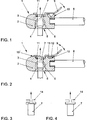
Gem.
Die Montage besagten Pfannenkörpers
Gesetzt den Fall, es ist erforderlich die Verbindung zwischen dem Pfannenkörper
Demgegenüber ist nunmehr ein Hebelelement
Wie in
Zwischen der Klemmfeder
Des Weiteren weist das Hebelelement
Das in
Ebenso ist es denkbar und wird durch die Erfindung mit erfasst, dass der erforderliche Freiraum
Wie in den
Selbstverständlich ist es auch denkbar, das Hebelelement
Nachfolgend wir die Funktionsweise der Erfindung näher erläutert.Subsequently, the operation of the invention will be explained in more detail.
Wie aus den
Das in
BezugszeichenlisteLIST OF REFERENCE NUMBERS
- 11
- Kugelgelenk-VerbindungssystemBall joint connection system
- 22
- Pfannenkörperpan body
- 33
- Kugelpfanneball socket
- 44
- Aufnahmekanalreceiving channel
- 55
- Einführungsöffnunginsertion opening
- 66
- Kugelbolzenball pin
- 77
- Klemmfederclamping spring
- 88th
- Kolbenstangepiston rod
- 99
- Hebelelementlever member
- 1010
- Drehpunktpivot point
- 10'10 '
- Drehpunktpivot point
- 1111
- Freiraumfree space
- 1212
- Abwinkelungangulation
- 1313
- Aussparungrecess
- 1414
- Zuglaschepull tab
Claims (6)
Priority Applications (1)
| Application Number | Priority Date | Filing Date | Title |
|---|---|---|---|
| DE200410050552 DE102004050552B4 (en) | 2004-10-16 | 2004-10-16 | Ball head connection system |
Applications Claiming Priority (1)
| Application Number | Priority Date | Filing Date | Title |
|---|---|---|---|
| DE200410050552 DE102004050552B4 (en) | 2004-10-16 | 2004-10-16 | Ball head connection system |
Publications (2)
| Publication Number | Publication Date |
|---|---|
| DE102004050552A1 DE102004050552A1 (en) | 2006-04-20 |
| DE102004050552B4 true DE102004050552B4 (en) | 2013-03-07 |
Family
ID=36120575
Family Applications (1)
| Application Number | Title | Priority Date | Filing Date |
|---|---|---|---|
| DE200410050552 Expired - Fee Related DE102004050552B4 (en) | 2004-10-16 | 2004-10-16 | Ball head connection system |
Country Status (1)
| Country | Link |
|---|---|
| DE (1) | DE102004050552B4 (en) |
Families Citing this family (2)
| Publication number | Priority date | Publication date | Assignee | Title |
|---|---|---|---|---|
| WO2016116955A1 (en) * | 2015-01-21 | 2016-07-28 | Fabio MANIERI | Spherical safety joint with manual or automatic coupling and quick release, with adjustable force |
| US10753386B2 (en) * | 2018-03-13 | 2020-08-25 | Ford Global Technologies, Llc | Quick release feature for gas assist struts |
Citations (5)
| Publication number | Priority date | Publication date | Assignee | Title |
|---|---|---|---|---|
| DE464438C (en) * | 1928-03-01 | 1928-08-17 | Fritz Faudi | Detachable ball joint |
| DE472636C (en) * | 1928-01-01 | 1929-03-02 | Massey Harris Company Ltd | Ball joint connection |
| AT201942B (en) * | 1957-07-20 | 1959-02-10 | Walter Ing Engelmann | Clevis for operating linkage |
| DE1675048A1 (en) * | 1967-03-17 | 1970-12-03 | Ft Products Ltd | Spring clip |
| DE2942800A1 (en) * | 1978-10-23 | 1980-05-22 | Gas Spring Corp | PAN CONSTRUCTION FOR A BALL JOINT |
-
2004
- 2004-10-16 DE DE200410050552 patent/DE102004050552B4/en not_active Expired - Fee Related
Patent Citations (5)
| Publication number | Priority date | Publication date | Assignee | Title |
|---|---|---|---|---|
| DE472636C (en) * | 1928-01-01 | 1929-03-02 | Massey Harris Company Ltd | Ball joint connection |
| DE464438C (en) * | 1928-03-01 | 1928-08-17 | Fritz Faudi | Detachable ball joint |
| AT201942B (en) * | 1957-07-20 | 1959-02-10 | Walter Ing Engelmann | Clevis for operating linkage |
| DE1675048A1 (en) * | 1967-03-17 | 1970-12-03 | Ft Products Ltd | Spring clip |
| DE2942800A1 (en) * | 1978-10-23 | 1980-05-22 | Gas Spring Corp | PAN CONSTRUCTION FOR A BALL JOINT |
Also Published As
| Publication number | Publication date |
|---|---|
| DE102004050552A1 (en) | 2006-04-20 |
Similar Documents
| Publication | Publication Date | Title |
|---|---|---|
| EP0229350A2 (en) | Actuation device with pedal and hinged push rod | |
| DE10328542B4 (en) | Pedal with mounting clip for push rod | |
| DE10050777B4 (en) | Air spring and method for manufacturing an air spring | |
| DE202008000220U1 (en) | mounting aid | |
| WO2007141117A1 (en) | Tensioning device for a traction mechanism, in particular a belt or a chain | |
| EP2226513A2 (en) | Clamping unit, in particular for use as a die closing unit | |
| DE102004050552B4 (en) | Ball head connection system | |
| DE102009022461A1 (en) | Actuation device for a parking brake | |
| DE102014211301A1 (en) | Assembly aid for the assembly of an actuating lever and an actuating rod of a brake booster | |
| DE19943750B4 (en) | Transmission element between a door handle and a door lock of a motor vehicle | |
| DE102017006742A1 (en) | Device for fastening an actuating rod of a brake booster to a brake pedal | |
| DE102007035641B3 (en) | transmission system | |
| DE102013208652A1 (en) | Fastening element for connecting transmission means to a lever element | |
| DE102004047910A1 (en) | Device for clamping or for displacing at least one top surface element | |
| DE102009027473B4 (en) | Clamp connection | |
| DE10230855B4 (en) | Pedal assembly and mounting method for this | |
| DE102005004432B3 (en) | Bowden cable`s core connecting device for motor vehicle seat, has lug, and sprocket hole for guiding end piece of core at front side of connecting unit in side piece gap and for preventing oscillating movement of piece in gap | |
| DE202008011150U1 (en) | Exhaust gas turbocharger for a motor vehicle | |
| DE102012209058A1 (en) | Windscreen wiper device for motor car, has aperture whose internal diameter is slightly smaller than outer diameter of assembly region of socket pad such that pad is attached into device by simply inserting and clipping pad into opening | |
| DE102018215197B4 (en) | Vehicle floor arrangement and vehicle with a vehicle floor arrangement | |
| DE102014203847A1 (en) | Arrangement for attaching a handle to an actuating lever | |
| DE19836703A1 (en) | Link fitting for two Bowden cables has few components and is simple to manufacture and fit | |
| EP2453147A1 (en) | Gear shift unit | |
| EP2037132A2 (en) | Clevis-type hooks | |
| DE102004018552B3 (en) | Device used as part of an emergency escape device for uncoupling a vehicle component and a body part comprises a counter element having a movable catch element forming a form- and/or force-locking connection |
Legal Events
| Date | Code | Title | Description |
|---|---|---|---|
| OM8 | Search report available as to paragraph 43 lit. 1 sentence 1 patent law | ||
| 8120 | Willingness to grant licences paragraph 23 | ||
| R012 | Request for examination validly filed |
Effective date: 20110423 |
|
| R016 | Response to examination communication | ||
| R018 | Grant decision by examination section/examining division | ||
| R020 | Patent grant now final |
Effective date: 20130608 |
|
| R119 | Application deemed withdrawn, or ip right lapsed, due to non-payment of renewal fee |