DE102004040749B4 - Smoke protection closure system - Google Patents

Smoke protection closure system Download PDF

Info

Publication number
DE102004040749B4
DE102004040749B4 DE102004040749.5A DE102004040749A DE102004040749B4 DE 102004040749 B4 DE102004040749 B4 DE 102004040749B4 DE 102004040749 A DE102004040749 A DE 102004040749A DE 102004040749 B4 DE102004040749 B4 DE 102004040749B4
Authority
DE
Germany
Prior art keywords
smoke
sealing element
smoke protection
fastening means
door
Prior art date
Legal status (The legal status is an assumption and is not a legal conclusion. Google has not performed a legal analysis and makes no representation as to the accuracy of the status listed.)
Expired - Fee Related
Application number
DE102004040749.5A
Other languages
German (de)
Other versions
DE102004040749A1 (en
Inventor
Patentinhaber gleich
Current Assignee (The listed assignees may be inaccurate. Google has not performed a legal analysis and makes no representation or warranty as to the accuracy of the list.)
Individual
Original Assignee
Individual
Priority date (The priority date is an assumption and is not a legal conclusion. Google has not performed a legal analysis and makes no representation as to the accuracy of the date listed.)
Filing date
Publication date
Application filed by Individual filed Critical Individual
Priority to DE102004040749.5A priority Critical patent/DE102004040749B4/en
Publication of DE102004040749A1 publication Critical patent/DE102004040749A1/en
Application granted granted Critical
Publication of DE102004040749B4 publication Critical patent/DE102004040749B4/en
Anticipated expiration legal-status Critical
Expired - Fee Related legal-status Critical Current

Links

Images

Classifications

    • EFIXED CONSTRUCTIONS
    • E06DOORS, WINDOWS, SHUTTERS, OR ROLLER BLINDS IN GENERAL; LADDERS
    • E06BFIXED OR MOVABLE CLOSURES FOR OPENINGS IN BUILDINGS, VEHICLES, FENCES OR LIKE ENCLOSURES IN GENERAL, e.g. DOORS, WINDOWS, BLINDS, GATES
    • E06B7/00Special arrangements or measures in connection with doors or windows
    • E06B7/16Sealing arrangements on wings or parts co-operating with the wings
    • E06B7/22Sealing arrangements on wings or parts co-operating with the wings by means of elastic edgings, e.g. elastic rubber tubes; by means of resilient edgings, e.g. felt or plush strips, resilient metal strips

Landscapes

  • Engineering & Computer Science (AREA)
  • Civil Engineering (AREA)
  • Structural Engineering (AREA)
  • Specific Sealing Or Ventilating Devices For Doors And Windows (AREA)
  • Special Wing (AREA)

Abstract

Rauchschutzabschlusssystem (100) zum Abschließen einer Öffnung in einer Wand (200) gegen einen Durchtritt von heißem und kaltem Rauch, umfassend: eine Rauchschutzabschlusseinrichtung (110) zum Abschließen der Öffnung gegen den Durchtritt von Rauch bis auf einen Zwischenraum (300) zwischen der Rauchschutzabschlusseinrichtung (110) und der Wand (200); wobei mindestens ein Dichtungselement (120) vorgesehen ist zum Abschließen des Zwischenraumes (300) gegen den Durchtritt von Rauch; mindestens ein Befestigungsmittel (130', 130'', 130''') vorgesehen ist zum Halten des Dichtungselementes (120); und das Befestigungsmittel (130', 130'', 130''') mit dem Dichtungselement (120) an der Wand (200) nachrüstbar ist; wobei die Rauchschutzabschlusseinrichtung (110) zwei Flügel (110-1, 110-2) aufweist, und mindestens ein zusätzliches Befestigungsmittel (130IV) mit einem zusätzlichen Dichtungselement (120IV) an mindestens einem der Flügel (110-1, 110-2) nachrüstbar ist zum Abdichten eines Spalts (350) zwischen den beiden Flügeln gegen einen Durchtritt von Rauch, wobei das Dichtungselement (120IV) derart positionierbar ist, dass es den Spalt (350) von außerhalb abschießt, dadurch gekennzeichnet, dass das Dichtungselement (120) ein Halterungsprofil (122) und ein Lippenprofil (126) sowie zusätzlich ein zwischen dem Halterungsprofil (122) und dem Lippenprofil (126) angeordnetes Federprofil (124) aufweist und das Befestigungsmittel (130', 130'', 130''') eine vorzugsweise trapezförmig hinterschnitten ausgebildete Nut (132) zur Aufnahme des Halterungsprofils (122) des Dichtungselementes (120) aufweist, wobei der Querschnitt oder zumindest die Hüllkurve des Querschnitts des Halterungsprofils (122) dann ebenfalls vorzugsweise entsprechend trapezförmig ausgebildet ist.A smoke control closure system (100) for closing an opening in a wall (200) against passage of hot and cold smoke, comprising: smoke protection termination means (110) for closing the opening against the passage of smoke to a gap (300) between the smoke protection closure means (11). 110) and the wall (200); wherein at least one sealing element (120) is provided for closing the gap (300) against the passage of smoke; at least one fastening means (130 ', 130' ', 130' '') is provided for holding the sealing element (120); and the fastening means (130 ', 130' ', 130' '') with the sealing element (120) on the wall (200) can be retrofitted; wherein the smoke barrier device (110) has two wings (110-1, 110-2) and at least one additional attachment means (130IV) with an additional sealing element (120IV) can be retrofitted to at least one of the wings (110-1, 110-2) for sealing a gap (350) between the two wings against passage of smoke, the sealing member (120IV) being positionable to fire the gap (350) from outside, characterized in that the sealing member (120) has a support profile (120); 122) and a lip profile (126) and in addition a between the support profile (122) and the lip profile (126) arranged spring profile (124) and the fastening means (130 ', 130' ', 130' '') formed a preferably trapezoidal undercut Groove (132) for receiving the support profile (122) of the sealing element (120), wherein the cross-section or at least the envelope of the cross section of the support profile (122) then also preferably designed according to trapezoidal.

Description

Die Erfindung betrifft ein Rauchschutzabschlusssystem zum Abschließen einer Öffnung in einer Wand gegen einen Durchtritt von Rauch gemäß dem Oberbegriff des Anspruchs 1.The invention relates to a smoke barrier system for closing an opening in a wall against the passage of smoke according to the preamble of claim 1.

Derartige Rauchschutzabschlusssysteme sind im Stand der Technik, insbesondere aus der DE 198 38 735 C1 , grundsätzlich bekannt. Das dort offenbarte Rauchschutzabschlusssystem umfasst eine Rauchschutzabschlusseinrichtung in Form einer Rauchschutztür zum Abschließen einer Öffnung gegen den Durchtritt von Rauch. Die Öffnung wird bei dem dort erwähnten Beispiel durch eine Türzarge als Bestandteil einer Wand sowie durch einen Fußbodenbereich begrenzt beziehungsweise definiert. Die Rauchschutztür ist ihrerseits rauchdicht ausgebildet, sodass ein Durchtritt von Rauch durch die Tür selbst nicht möglich ist. Bei geschlossener Rauchschutztür besteht allerdings zwischen der Rauchschutztür und dem Türzargen- beziehungsweise dem Fußbodenbereich ein Zwischenraum, d. h. Spalt, durch den ein Rauchdurchtritt grundsätzlich möglich ist. Um dies zu verhindern, ist die Türzarge auf der Schließseite der Rauchschutztür in Form einer trapezförmigen hinterschnittenen Nut ausgebildet. Diese Nut dient als Befestigungsmittel zum Fixieren eines Dichtungselementes, welches bei geschlossener Rauchschutztür gegen deren Schließseite drückt und auf diese Weise den Zwischenraum von der Schließseite der Raumschutztür her gegen Rauch dicht abschließt.Such Rauchschutzabschlusssysteme are in the prior art, in particular from DE 198 38 735 C1 , basically known. The smoke shut-off system disclosed therein includes a smoke shut-off device in the form of a smoke door for closing an opening against the passage of smoke. The opening is limited or defined in the example mentioned there by a door frame as part of a wall and by a floor area. The smoke door is in turn smoke-proof, so that passage of smoke through the door itself is not possible. When the smoke protection door is closed, however, there is a space between the smoke protection door and the Türzargen- or the floor area, ie gap, through which a smoke passage is basically possible. To prevent this, the door frame is formed on the closing side of the smoke door in the form of a trapezoidal undercut groove. This groove serves as a fastening means for fixing a sealing element, which presses against the closing side with the smoke protection door closed and in this way tightly seals the gap from the closing side of the space protection door against smoke.

Anders als bei dem aus der DE 198 38 735 C1 bekannten Rauchschutzabschlusssystem sind auch Rauchschutzabschlusssysteme, insbesondere Rauchabschlusstüren bekannt, welche von Zargen aufgenommen werden, welche auf der Schließseite der Rauchabschlusstür nicht in Form einer Nut zur Aufnahme eines Dichtungselementes ausgebildet sind. Auch andere Rauchschutz-Dichtelemente sind dort nicht vorhanden. Bei derartigen Rauchschutzabschlusssystemen besteht die Gefahr, dass Rauch durch den Zwischenraum zwischen der Rauchschutztür und der Türzarge beziehungsweise dem Fußbodenbereich hindurchtritt. Eine derartige Situation findet sich häufig bei sogenannten Feuerschutztüren, die zwar ihrerseits ausgebildet sind, einen Durchtritt von Flammen sowie einen übermäßigen Temperaturanstieg zu verhindern, bei denen aber ein Durchtritt von – insbesondere kaltem – Rauch durch den Zwischenraum toleriert wird.Unlike the one from the DE 198 38 735 C1 known Rauchschutzabschlusssystem are also Rauchschutzabschlusssysteme, in particular smoke doors are known, which are received by frames which are not formed on the closing side of the smoke door in the form of a groove for receiving a sealing element. Other smoke protection sealing elements are not available there. In such Rauchschutzabschlusssystemen there is a risk that smoke passes through the gap between the smoke door and the door frame or the floor area. Such a situation is often found in so-called fire doors, which in turn are designed to prevent the passage of flames and excessive temperature rise, but in which a passage of - especially cold - smoke is tolerated by the gap.

Ein derartiger Durchtritt von Rauch durch den besagten Zwischenraum ist bei modernen Rauchschutzabschlusssystemen, insbesondere wenn sie einer Rauchschutzprüfung nach DIN 18 095 Teil 1 Okt 1988 und Teil 2 Mrz 1991 beziehungsweise DIN EN 1634-3:2002-02 genügen sollen, nicht mehr akzeptabel; vielmehr wird bei diesen Systemen gefordert, dass sie eine Öffnung möglichst vollständig gegen Rauchdurchtritt abschließen bzw. dass der Rauchdurchtritt bestimmte Volumina pro Stunde nicht übersteigt.Such passage of smoke through said gap is no longer acceptable in modern smoke protection systems, especially if they are to comply with a smoke protection test according to DIN 18 095 Part 1 Oct 1988 and Part 2 Mar 1991 or DIN EN 1634-3: 2002-02; rather, these systems require that they complete an opening as completely as possible against the passage of smoke or that the passage of smoke does not exceed certain volumes per hour.

Bei zum Beispiel in Gebäuden eingebauten Feuerschutztüren, an die noch keine genormten Anforderungen an den Rauchschutz gestellt wurden, stellt sich nun die Frage, wie bei derartigen Systemen beziehungsweise Türen der Rauchdurchtritt nachträglich minimiert beziehungsweise vollständig unterbunden werden kann.For example, when installed in buildings fire doors to which no standardized requirements for smoke protection have been made, now the question arises, such as in such systems or doors, the smoke passage can be subsequently minimized or completely prevented.

Eine Lösung wäre sicherlich der Austausch der bisher eingebauten Türen gegen modernere Rauchabschlusstüren (eventuell kombiniert mit Feuerschutzfunktion), welche einen wesentlich reduzierten Rauchdurchtritt gewährleisten würden. Der Austausch der kompletten Türen ist jedoch in der Regel sehr kostenintensiv und auch in bestehenden Gebäuden unter Aufrechterhaltung eines Betriebs (zum Beispiel innerhalb eines Krankenhauses) nur sehr schwer möglich.A solution would certainly be the replacement of the previously installed doors against more modern smoke-tight doors (possibly combined with fire protection function), which would ensure a significantly reduced passage of smoke. However, the replacement of the complete doors is usually very costly and in existing buildings while maintaining an operation (for example, within a hospital) is very difficult.

Weitere Rauchschutzabschlusssysteme sind aus den Dokumenten DE 78 02 670 U1 , DE 25 43 685 A1 , GB 2 106 972 A , DE 100 55 214 C1 , DE 42 26 702 A1 , DE 37 20 287 A1 und DE 78 14 836 U1 bekannt, wobei sich die DE 78 14 836 U1 analog zu der vorliegenden Anmeldung mit der Rauchabdichtung von zweiflügeligen Türen befasst.Other smoke protection systems are from the documents DE 78 02 670 U1 . DE 25 43 685 A1 . GB 2 106 972 A . DE 100 55 214 C1 . DE 42 26 702 A1 . DE 37 20 287 A1 and DE 78 14 836 U1 known, with the DE 78 14 836 U1 similar to the present application deals with the smoke seal of double-leaf doors.

Ferner offenbart die DE 28 31 998 A1 eine Isoliertürvorrichtung, die als zweiflügelige Tür ausgebildet sein kann. Die Dichtungen zur Abdichtung der Spalte zwischen dem Türblatt und dem Gebäude bzw. zwischen benachbarten Türblättern sollen fluiddicht ausgebildet werden, wobei die Dichtheit überprüfbar sein soll.Further, the DE 28 31 998 A1 an insulated door device, which may be formed as a double-leaf door. The seals for sealing the gaps between the door leaf and the building or between adjacent door leaves should be formed fluid-tight, the tightness should be verifiable.

Schließlich befassen sich die Dokumente DE 296 19 448 U1 und DD 243 316 A1 mit Brandschutztüren, bei denen die Spalte bekanntermaßen mit im Brandfall aufquellenden Dichtungsleisten versehen sind. Hier ist eine Abdichtung nur bei Auftritt von heißem Rauch möglich.Finally, the documents are concerned DE 296 19 448 U1 and DD 243 316 A1 with fire doors, where the gaps are known to be provided with in case of fire swelling sealing strips. Here is a seal only possible when hot smoke occurs.

Die Nachrüstbarkeit steht bei den vorgenannten Schriften nicht im Fokus.The retrofittability is not in the focus of the aforementioned publications.

Ausgehend von diesem Stand der Technik ist es deshalb die Aufgabe der Erfindung, ein bekanntes Rauchschutzabschlusssystem ohne ursprünglich vorgesehene Mittel zum Abschließen des besagten Zwischenraumes derart weiterzubilden, dass ein Abschluss des Zwischenraumes gegen einen Durchtritt von heißem oder kalten Rauch auch nach dem Einbau des Systems in eine Wand oder eine Öffnung noch preisgünstig möglich ist.Based on this prior art, it is therefore the object of the invention to develop a known Rauchschutzabschlusssystem without originally provided means for closing the said gap such that a conclusion of the gap against a passage of hot or cold smoke even after installation of the system in a Wall or an opening is still inexpensive possible.

Diese Aufgabe wird durch den Gegenstand des Patentanspruchs 1 gelöst. Demnach erfolgt die Lösung dadurch, dass das Dichtungselement ein Halterungsprofil und ein Lippenprofil sowie zusätzlich ein zwischen dem Halterungsprofil und dem Lippenprofil angeordnetes Federprofil aufweist und das Befestigungsmittel eine vorzugsweise trapezförmig hinterschnitten ausgebildete Nut zur Aufnahme des Halterungsprofils des Dichtungselementes aufweist, wobei der Querschnitt oder zumindest die Hüllkurve des Querschnitts des Halterungsprofils dann ebenfalls vorzugsweise entsprechend trapezförmig ausgebildet ist. Auch wenn die Nachrüstung vorzugsweise an allen vier Seiten einer in der Regel rechteckigen Rauchschutzabschlusseinrichtung, d. h. Tür, erfolgt, treten die Vorteile der Verminderung des Rauchdurchtritts auch bereits bei der Dichtungsnachrüstung von nur „drei der vier Seiten”, oder sogar weniger, ein. This object is solved by the subject matter of patent claim 1. Accordingly, the solution is characterized in that the sealing element has a support profile and a lip profile and additionally arranged between the support profile and the lip profile spring profile and the fastening means has a preferably trapezoidal undercut formed groove for receiving the support profile of the sealing element, wherein the cross section or at least the envelope the cross section of the support profile then also preferably correspondingly trapezoidal. Although the retrofit is preferably on all four sides of a generally rectangular smoke shut-off device, ie, door, the benefits of reducing the fume passage already occur in gasket retrofitting of only "three of the four sides," or even less.

Die nachrüstbare Ausbildung des Befestigungsmittels ermöglicht eine preisgünstige Befestigung des Befestigungsmittels für das Dichtelement an der Wand und/oder an der Rauchschutzabschlusseinrichtung auch nach deren Einbau. Das Nachrüsten des Befestigungsmittels mit dem Dichtungselement ist wesentlich preisgünstiger als der Austausch der kompletten Rauchschutzabschlusseinrichtung, insbesondere in Form einer neuen Rauchabschlusstür.The retrofittable design of the fastener allows a low-cost attachment of the fastener for the sealing element on the wall and / or on the smoke protection termination device even after their installation. The retrofitting of the fastener with the sealing element is much cheaper than the replacement of the complete smoke protection device, especially in the form of a new smoke door.

Das Federprofil zwischen dem Halterungsprofil und dem Lippenprofil ermöglicht ein dichtabschließendes Anliegen des Lippenprofils an der Rauchschutzabschlusseinrichtung oder der Wand unter Vorspannung.The spring profile between the support profile and the lip profile allows a dichtabschließendes concern of the lip profile on the smoke protection termination device or the wall under bias.

Die mechanische Halterung umfasst eine vorzugsweise trapezförmig ausgebildete Nut zur Aufnahme des Halterungsprofils des Dichtungselementes. Wenn der Querschnitt oder zumindest die Hüllkurve des Querschnitts des Halterungsprofils entsprechend trapezförmig ausgebildet ist, wird das Halterungsprofil und damit das gesamte Dichtungselement von der mechanischen Halterung sicher gehalten, ohne dass es herausfällt.The mechanical support comprises a preferably trapezoidal groove for receiving the support profile of the sealing element. If the cross section or at least the envelope of the cross section of the support profile is correspondingly trapezoidal, the support profile and thus the entire sealing element is held securely by the mechanical support without it falling out.

In einer besonders vorteilhaften Ausgestaltung kommt das Dichtungselement mit seinen sich in Längsrichtung erstreckenden Kontaktstreifen mit der Schließseite der Rauchschutzabschlusseinrichtung in Berührung und ragt dabei zumindest zum Teil in den ohne nachgerüstetes Dichtungselement freien Querschnitt der Öffnung hinein.In a particularly advantageous embodiment, the sealing element with its contact strip extending in the longitudinal direction comes into contact with the closing side of the smoke protection closing device and protrudes at least partially into the free cross-section of the opening without a retrofitted sealing element.

Vorteilhafterweise kann das Befestigungsmittel auch auf der Schließseite der Rauchabschlusstür auf einem Fußbodenbereich befestigt sein, wenn dieser einen Abschnitt des Zwischenraumes begrenzt. Nach dem Einsetzen der Dichtung in das Befestigungsmittel ist dann sichergestellt, dass durch den Zwischenraum zwischen dem Fußbodenbereich und der Stirnunterseite der Rauchabschlusstür kein Rauch mehr hindurchtritt. Das auf dem Fußbodenbereich befestigte Befestigungsmittel birgt allerdings die Gefahr in sich, dass ein Fußgänger darüber stolpern kann. Deshalb ist das Nachrüsten des Befestigungsmittels auf dem Fußbodenbereich lediglich in Bereichen ohne Publikumsverkehr, das heißt zum Beispiel in Betriebsräumen, zulässig.Advantageously, the fastening means may also be mounted on the closing side of the smoke door on a floor area, if this limits a portion of the intermediate space. After inserting the seal in the fastener is then ensured that no smoke passes through the space between the floor area and the front bottom of the smoke door. The fastener fastened to the floor area, however, carries the risk that a pedestrian may trip over it. Therefore, the retrofitting of the fastener on the floor area only in areas without public traffic, that is, for example, in operating rooms, allowed.

Alternativ oder zusätzlich zu einem Nachrüsten des Befestigungsmittels auf dem Fußboden bereich empfiehlt sich ein Nachrüsten des Befestigungsmittels auf der Öffnungsseite und/oder der Schließseite der Rauchabschlusstür insbesondere so, dass der Abschnitt des Zwischenraumes zwischen der Rauchabschlusstür und dem Fußbodenbereich gegen Rauchdurchtritt abgeschlossen ist.Alternatively or in addition to a retrofitting of the fastener on the floor area, retrofitting of the fastener on the opening side and / or the closing side of the smoke door is particularly recommended so that the portion of the space between the smoke door and the floor area is sealed against passage of smoke.

Das Befestigungsmittel kann als mechanische Halterung, vorzugsweise aus Metall gebogen, ausgebildet sein. In diesem Fall empfiehlt es sich, in der mechanischen Halterung ein Langloch vorzusehen, welches bei der Befestigung der Halterung mit z. B. einer Schraube ein exaktes Positionieren der Halterung in der Weise ermöglicht, dass das Dichtungselement an der Rauchabschlusstür bzw. an einem Öffnungsrandbereich, d. h. an der Wand oder dem Fußbodenbereich anliegt; nur auf diese Weise wird sicher gestellt, dass das Dichtungselement den jeweiligen Abschnitt des Zwischenraumes auch tatsächlich dicht gegen Rauch abschließt.The fastening means may be formed as a mechanical support, preferably bent from metal. In this case, it is recommended to provide a slot in the mechanical holder, which in the attachment of the holder with z. B. a screw allows an exact positioning of the holder in such a way that the sealing element on the smoke door or at an opening edge portion, d. H. on the wall or floor area; only in this way it is ensured that the sealing element actually closes the respective portion of the gap tightly against smoke.

Um zu verhindern, dass ein Durchtritt von Rauch zwischen der Unterseite des als mechanische Halterung ausgebildeten Befestigungsmittels und der Wand bzw. der Rauchschutzabschlusseinrichtung möglich ist, ist es vorteilhaft, an den Anschlussstellen zwischen der Halterung und der Wand bzw. der Rauchschutzabschlusseinrichtung eine Dichtmasse vorzusehen.In order to prevent a passage of smoke between the underside of the fastener formed as a mechanical support and the wall or the smoke protection device is possible, it is advantageous to provide a sealant at the connection points between the holder and the wall or the smoke protection.

Alternativ zu der Ausbildung als mechanische Halterung kann das Befestigungsmittel auch als Klebstoff ausgebildet sein. Bei der Ausbildung als Klebstoff erübrigt sich vorteilhafter Weise das Vorsehen von Dichtmasse zum Abdichten der Anschlussstellen. Außerdem ist der Kosten- und Zeitaufwand zum Nachrüsten des Befestigungsmittels geringer als bei der mechanischen Halterung.As an alternative to the embodiment as a mechanical holder, the fastening means can also be designed as an adhesive. When forming the adhesive, the provision of sealing compound for sealing the connection points is advantageously unnecessary. In addition, the cost and time to retrofit the fastener is less than the mechanical support.

Zusätzlich zu den bisher beschriebenen Maßnahmen zum Abschließen des Zwischenraums gegen einen Durchtritt von Rauch kann in dem Zwischenraum auch mindestens eine Brandschutzleiste vorgesehen sein. Brandschutzleisten haben die Eigenschaft, dass sie bei größeren Temperaturen, z. B. über 250°C aufschäumen und dann einen Damm in dem Zwischenraum ausbilden, welcher einen Durchtritt von insbesondere Rauch durch den Zwischenraum verhindert.In addition to the measures described so far for closing off the intermediate space against the passage of smoke, at least one fire protection strip can also be provided in the intermediate space. Fire bars have the property that they at higher temperatures, eg. B. over 250 ° C and then form a dam in the space, which is a Passage of particular smoke through the gap prevents.

Besonders vorteilhaft ist es, wenn in dem Zwischenraum in Rauchdurchtrittsrichtung zunächst eine erste Brandschutzleiste, dahinter ein Dichtungsprofil und dahinter wiederum eine zweite Brandschutzleiste angeordnet sind. Dann spielt es keine Rolle, ob Rauch von der Öffnungs- oder der Schließseite der Rauchabschlusstür her versuchen würde, durch den Zwischenraum hindurchzutreten; die jeweils zum Raucheintrittsort nächstgelegene Brandschutzleiste wird dann bei entsprechend hoher Temperatur zunächst aufschäumen. Der auf diese Weise entstehende Damm bildet einen Schutz innerhalb des Zwischenraumes für das dahinter angeordnete Dichtungsprofil; insbesondere repräsentiert der Damm eine Temperaturbarriere, welche verhindert, dass das Dichtungsprofil hinter dem Damm auf Grund zu hoher Temperatureinwirkung zerstört wird, insbesondere schmilzt. So wird die Funktionsfähigkeit des Dichtungsprofils als zusätzliche Rauchschutzabschlusseinrichtung auch bei hohen Temperaturen sichergestellt.It is particularly advantageous if first a fire protection strip, behind a sealing profile and in turn a second fire protection strip are arranged in the intermediate space in the smoke penetration direction. Then it does not matter if smoke from the opening or closing side of the smoke door would try to pass through the gap; the nearest to the smoke entry nearest fire protection strip will then foam at a correspondingly high temperature first. The resulting dam forms a protection within the gap for the behind arranged sealing profile; In particular, the dam represents a temperature barrier, which prevents the sealing profile behind the dam is destroyed due to high temperature exposure, in particular melts. This ensures that the sealing profile functions as an additional smoke protection device even at high temperatures.

Ferner ist noch vorgesehen, dass das Befestigungsmittel mit einem elastischen Dichtmittel gegenüber der Wand oder der Rauchschutzabschlusseinrichtung abgedichtet ist, um dort einen Rauchdurchtritt zu unterbinden.Furthermore, it is provided that the fastening means is sealed with an elastic sealant against the wall or the smoke protection device to prevent smoke passage therethrough.

Außerdem kann es zweckmäßig sein das Befestigungsmittel mittels eines angepassten Abdeckprofils zu verkleiden, um eine optisch ansprechende Nachrüstlösung zu erzielen.In addition, it may be appropriate to disguise the fastener by means of a customized cover profile in order to achieve a visually appealing retrofit solution.

Die Erfindung wird nachfolgend anhand von Ausführungsbeispielen, die in der Zeichnung dargestellt sind, näher erläutert:The invention will be explained in more detail below with reference to exemplary embodiments which are illustrated in the drawing:

Es zeigt:It shows:

1 ein Rauchschutzabschlusssystem gemäß dem Stand der Technik; 1 a smoke protection system according to the prior art;

2 einen Schnitt durch das Rauchschutzabschlusssystem nach 1 in Längsrichtung; 2 a section through the smoke protection system after 1 longitudinal;

3 eine Detailansicht von 2 mit einer weiteren nicht erfindungsgemäßen Variante; 3 a detailed view of 2 with a further variant not according to the invention;

4 einen Schnitt durch das Rauchschutzabschlusssystem gemäß 1 in Querrichtung; 4 a section through the smoke protection system according to 1 in the transverse direction;

5 eine Detailansicht von 4; 5 a detailed view of 4 ;

6 eine erfindungsgemäße Rauchabschlusstür mit zwei Flügeln und 6 a smoke door according to the invention with two wings and

7 einen Ausschnitt aus 6 mit einer Variante für ein Dichtungselement. 7 a section from 6 with a variant for a sealing element.

Die Erfindung wird nachfolgend unter Bezugnahme auf die genannten Figuren detailliert beschrieben: In allen Figuren sind gleiche Elemente mit gleichen Bezugszeichen bezeichnet.The invention is described in detail below with reference to the cited figures: In all figures, the same elements are designated by the same reference numerals.

1 zeigt ein nicht die vorliegende Erfindung betreffendes Rauchschutzabschlusssystem 100 zum Abschließen einer Öffnung in einer Wand 200 gegen einen Durchtritt von Rauch. Bei der Öffnung handelt es sich beispielsweise um eine Türöffnung, welche in 1 durch eine Rauchschutzabschlusseinrichtung 110 in Form einer Rauchabschlusstür verdeckt und deshalb nicht als solche zu erkennen ist. Ein Öffnungsrandbereich, welcher die Öffnung begrenzt und definiert, wird in 1 durch eine Türzarge 212 als Bestandteil der Wand 200 sowie durch einen Fußbodenbereich 214 gebildet. Die Rauchabschlusstür 110 schließt die Öffnung bis auf einen Zwischenraum 300 zwischen der Rauchabschlusstür 110 und dem Öffnungsrandbereich gegen den Durchtritt von Rauch ab. 1 Figure 11 shows a smoke control termination system 100 not in accordance with the present invention for closing an opening in a wall 200 against a passage of smoke. The opening is, for example, a door opening, which in 1 through a smoke protection device 110 hidden in the form of a smoke door and therefore can not be recognized as such. An opening edge area which bounds and defines the opening is in 1 through a door frame 212 as part of the wall 200 as well as through a floor area 214 educated. The smoke door 110 closes the opening except for a gap 300 between the smoke door 110 and the opening edge area against the passage of smoke.

2 zeigt einen Schnitt durch das nicht die Erfindung betreffende Rauchschutzabschlusssystem 100 gemäß 1 in Längsrichtung. Es ist zu erkennen, dass die Zarge 212 die Wand 200 zu der Rauchabschlusstür 110 hin begrenzt und die Rauchabschlusstür in geschlossenem Zustand aufnimmt. Die Rauchabschlusstür 110 hat eine Schließseite S und eine Öffnungsseite Oe. 2 shows a section through the non-invention invention smoke protection system 100 according to 1 longitudinal. It can be seen that the frame 212 the wall 200 to the smoke door 110 limited and receives the smoke door in the closed state. The smoke door 110 has a closing side S and an opening side Oe.

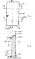
Um zu verhindern, dass Rauch durch den Zwischenraum 300 zwischen der Rauchabschlusstür 110 und dem Öffnungsrandbereich von der Öffnungsseite Oe auf die Schließseite S oder umgekehrt hindurchtritt, ist es zweckmäßig, diesen Zwischenraum auf der Schließseite S, wie in 2 gezeigt, abzudichten. Zu diesem Zweck ist auf der Schließseite mindestens ein Befestigungsmittel 130', 130'' in Form einer metallischen Halterung zum Halten eines Dichtungselementes 120 an dem Öffnungsrandbereich abschnittweise nachgerüstet. Ein erster Abschnitt des Öffnungsrandbereiches wird durch den in 2 gezeigten oberen Bereich der Wand 200 mit der Türzarge 212 repräsentiert, welcher gegenüber der Stirnoberseite der Rauchabschlusstür 110 ausgebildet ist. Bei dem in 2 gezeigten Ausführungsbeispiel, das nicht die vorliegende Erfindung betrifft, ist das Befestigungsmittel 130' unmittelbar an der Wand 200 befestigt; in einer dazu alternativen – nicht gezeigten – Ausführungsform, kann das Befestigungsmittel 130' auch direkt an dem Zargen 212 befestigt sein, insbesondere wenn der Zargen in dem Bereich des Befestigungsmittels 130' noch einen zusätzlichen horizontalen Abschnitt (nicht gezeigt) aufweist.To prevent smoke from passing through the gap 300 between the smoke door 110 and the opening edge portion passes from the opening side Oe to the closing side S or vice versa, it is desirable to make this clearance on the closing side S as in FIG 2 shown to seal. For this purpose, at least one fastening means is on the closing side 130 ' . 130 '' in the form of a metallic holder for holding a sealing element 120 partially retrofitted at the opening edge area. A first portion of the opening edge region is defined by the in 2 shown upper area of the wall 200 with the door frame 212 represents, which opposite the front surface of the smoke door 110 is trained. At the in 2 shown embodiment, which does not relate to the present invention is the fastener 130 ' immediately on the wall 200 attached; in an alternative - not shown - embodiment, the fastening means 130 ' also directly on the frame 212 be attached, especially if the frame in the region of the fastener 130 ' still has an additional horizontal portion (not shown).

Das Befestigungselement 130' dient zum Halten des Dichtungselementes 120, welches dicht an der Schließseite S der Rauchabschlusstür 110 anliegt, sodass ein Durchtritt von Rauch durch den Zwischenraum 300 weder von der Schließseite S auf die Öffnungsseite Oe noch umgekehrt möglich ist. Das Befestigungsmittel 130' ist bei allen Abschnitten des Zwischenraumes vorzusehen, durch welche ein Durchtritt von Rauch grundsätzlich möglich ist; erforderlichenfalls umlaufend entlang des gesamten Öffnungsrandbereiches, insbesondere entlang der Wand bzw. des Zargen. The fastener 130 ' serves to hold the sealing element 120 , which is close to the closing side S of the smoke door 110 so that passage of smoke through the gap 300 neither from the closing side S on the opening side Oe nor vice versa is possible. The fastener 130 ' is to be provided in all sections of the intermediate space through which a passage of smoke is possible in principle; if necessary, circumferentially along the entire opening edge region, in particular along the wall or the frame.

Um auch einen Durchtritt von Rauch durch denjenigen Abschnitt des Zwischenraumes 300 zu verhindern, welcher durch die Stirnunterseite der Rauchabschlusstür und den Fußbodenbereich 214 begrenzt ist, ist in 2 ein weiteres Befestigungsmittel 130'' auf der Schließseite S der Rauchabschlusstür 110 vorgesehen. Dieses Befestigungsteil 130'' ist in 3 vergrößert dargestellt, die sich ebenfalls nicht auf die vorliegende Erfindung bezieht.To also allow passage of smoke through that section of the gap 300 to prevent which through the forehead bottom the smoke door and the floor area 214 is limited is in 2 another fastener 130 '' on the closing side S of the smoke door 110 intended. This fastening part 130 '' is in 3 shown enlarged, which also does not relate to the present invention.

In 3 ist zu erkennen, dass das Nachrüsten des Befestigungsmittels 130'' auf dem Fußbodenbereich 214 zum Beispiel mit einer Schraube als Verbindungselement 400 erfolgen kann. Dabei wird die Schraube durch ein Loch innerhalb des Befestigungsmittels 130 geführt, welches vorzugsweise als Langloch ausgebildet ist (nicht gezeigt). Die Ausbildung des Schraubenloches in der mechanischen Halterung 130 als Langloch bietet den Vorteil, dass das Befestigungsmittel in Pfeilrichtung, d. h. quer zur Ebene der Rauchschutzabschlusstür 110, genau so positioniert werden kann, dass das von dem Befestigungsmittel 130'' gehaltene Dichtungselement 120 ordnungsgemäß, d. h. rauchabschließend, an der schließseitigen Oberfläche S der Rauchabschlusstür 110 anliegt.In 3 it can be seen that the retrofitting of the fastener 130 '' on the floor area 214 for example with a screw as a connecting element 400 can be done. The screw is passed through a hole in the fastener 130 guided, which is preferably designed as a slot (not shown). The formation of the screw hole in the mechanical holder 130 As a slot has the advantage that the fastener in the direction of the arrow, ie transverse to the level of Rauchabsabschlusstür 110 , can be positioned exactly that of the fastener 130 '' held sealing element 120 properly, ie smoke-free, on the closing surface S of the smoke door 110 is applied.

Das Dichtungselement 120 umfasst ein Halterungsprofil 122 und ein Lippenprofil 126. Optional kann zwischen dem Halterungsprofil 122 und dem Lippenprofil 126 ein Federprofil 124 vorgesehen sein. Das Halterungsprofil dient zum Halten des Dichtungselementes 120 in einer Nut 132 des Befestigungsmittels 130. Um eine Verankerung des Halterungsprofils in der Nut zu gewährleisten, sind vorzugsweise sowohl die hinterschnittene Nut, wie auch das Halterungsprofil 122 trapezförmig ausgebildet. Genauer gesagt ist der Querschnitt bzw. die Hüllkurve des Querschnittes des Halterungsprofils 122 so ausgebildet, dass das Halterungsprofil passgenau von der Nut aufgenommen werden kann, wie in 3 gezeigt. Das Federungsprofil 124 hat eine Pufferwirkung und dient zur Gewährleistung einer Anpresskraft des Lippenprofils 126 an die Schließseite S der Rauchabschlusstür 110.The sealing element 120 includes a bracket profile 122 and a lip profile 126 , Optionally, between the bracket profile 122 and the lip profile 126 a spring profile 124 be provided. The support profile serves to hold the sealing element 120 in a groove 132 of the fastener 130 , In order to ensure anchoring of the support profile in the groove, preferably both the undercut groove, as well as the support profile 122 trapezoidal shaped. More specifically, the cross section and the envelope of the cross section of the support profile 122 designed so that the support profile can be accurately absorbed by the groove, as in 3 shown. The suspension profile 124 has a buffer effect and serves to ensure a contact pressure of the lip profile 126 to the closing side S of the smoke door 110 ,

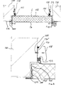
Weiterhin ist es empfehlenswert, wenn an den Anschlussstellen, d. h. in den Übergangsbereichen des Befestigungsmittels 130 zu der Wand 200, dem Fußbodenbereich 214 oder der Rauchabschlusstür, eine Dichtmasse 134' vorgesehen ist zum Abdichten der besagten Anschlussstellen gegen Rauchdurchtritt. Eine erste Möglichkeit zum Positionieren der Dichtmasse ist in 3 gezeigt. Dort ist die Dichtmasse 134' zwischen einer Außenwand einer U-profilförmigen Ausprägung des Befestigungsmittels 130'' und dem Untergrund, d. h. dem Fußbodenbereich 214 vorgesehen, auf dem das Befestigungsmittel 130'' befestigt ist. Eine zweite Möglichkeit ist in 5 gezeigt, wonach die Dichtmasse 134'' im Innern der U-profilförmigen Ausprägung eingebracht ist.Furthermore, it is recommended if at the connection points, ie in the transition areas of the fastener 130 to the wall 200 , the floor area 214 or the smoke door, a sealant 134 ' is provided for sealing said connection points against the passage of smoke. A first possibility for positioning the sealant is in 3 shown. There is the sealant 134 ' between an outer wall of a U-profile shape of the fastener 130 '' and the ground, ie the floor area 214 provided on which the fastener 130 '' is attached. A second option is in 5 shown, after which the sealant 134 '' is introduced in the interior of the U-shaped profile.

Neben der soeben beschriebenen Variante zum Anbringen des Befestigungsmittels, welche eine Montage des Befestigungsmittels 130 auf dem schließseitigen Fußbodenbereich 214 vorsieht, ist in 3 auch eine weitere Variante zum Anbringen des Befestigungsmittels 130 gezeigt. Diese weitere Variante sieht vor, dass das Befestigungsmittel 130'' auf der Öffnungsseite Oe der Rauchabschlusstür 110 montiert wird. Das Befestigungsmittel 130'' in Form der mechanischen Halterung kann bei beiden Varianten gleichartig ausgebildet sein. Allerdings verbietet sich eine Befestigung des Befestigungsmittels 130''' gemäß der weiteren Variante, d. h. auf dem öffnungsseitigen Fußbodenbereich 214, weil dann ein Öffnen der Rauchabschlusstür 110 nicht mehr möglich wäre. Bei einer Befestigung des Befestigungsmittels 130''' an der Öffnungsseite Oe der Rauchabschlusstür, wie in 3 gezeigt, ist die Befestigungseinrichtung 130''' zusammen mit dem Dichtungselement 120 in vertikaler Richtung so zu positionieren, dass das Lippenprofil 126 des Dichtungselementes dicht, das heißt rauchabschließend, auf dem Fußbodenbereich 214 anliegt bzw. auf diesen drückt. Die weitere Variante kann alternativ oder zusätzlich zu der zuvor beschriebenen Variante vorgesehen sein.In addition to the just described variant for attaching the fastener, which is a mounting of the fastener 130 on the closing floor area 214 Provides is in 3 Also another variant for attaching the fastener 130 shown. This further variant provides that the fastener 130 '' on the opening side Oe of the smoke door 110 is mounted. The fastener 130 '' in the form of the mechanical support can be formed identically in both variants. However, an attachment of the fastener prohibits 130 ''' according to the further variant, ie on the opening side floor area 214 because then opening the smoke door 110 no longer possible. When fixing the fastener 130 ''' at the opening side Oe of the smoke door, as in 3 shown is the fastening device 130 ''' together with the sealing element 120 in the vertical direction to position the lip profile 126 the sealing element tight, that is smoke-free, on the floor area 214 is present or presses on this. The further variant may be provided as an alternative or in addition to the previously described variant.

Alternativ zu einer Ausbildung des Befestigungsmittels 130 als mechanische Halterung, kann das Befestigungsmittel 130 auch als Klebstoffverbindung ausgebildet sein. Die Ausbildung als Klebstoff bzw. Klebstoffverbindung wäre gegenüber der Ausbildung des Befestigungsmittels 130 als mechanische Halterung wesentlich kostengünstiger, nicht zuletzt deswegen, weil dann die mechanische Halterung als solche sowie die zusätzliche Dichtungsmasse 134 entbehrlich wären.Alternatively to a design of the fastener 130 As a mechanical bracket, the fastener can 130 Also be designed as an adhesive connection. The training as an adhesive or adhesive connection would be compared to the formation of the fastener 130 as a mechanical support much cheaper, not least because then the mechanical support as such and the additional sealant 134 could be dispensable.

4 zeigt einen Querschnitt durch das nicht die Erfindung betreffende Rauchschutzabschlusssystem, insbesondere die Rauchabschlusstür 110, entlang einer Querrichtung, wie in 1 angedeutet. Besonders deutlich ist in 4 der Zwischenraum 300 zwischen der Rauchabschlusstür 110 und der Türzarge 212 zu erkennen; der Zwischenraum erstreckt sich grundsätzlich – wenn auch abschnittsweise evtl. mit jeweils unterschiedlicher Breite – durchgehend von der Schließseite S zu der Öffnungsseite Oe der Rauchabschlusstür. Im Bereich der Stirnseiten der Rauchabschlusstür 110 hat dieser Zwischenraum 300 eine Breite von B. Um einen Rauchdurchtritt durch diesen Zwischenraum zu verhindern ist es deswegen grundsätzlich erforderlich, eine Abdichtung umlaufend im Übergangsbereich zwischen der Rauchabschlusstür 110 und der Türzarge 212 bzw. der Wand 200 vorzusehen. Dies kann z. B. mit Hilfe der oben beschriebenen Dichtungselemente 120 erfolgen, welche mit Hilfe der Befestigungsmittel 130', 130'', 130''' an der Rauchabschlusstür 110 oder der Wand 200, insbesondere dem Türzargen 212 befestigt sind. Die Dichtungselemente 120 werden nicht direkt in dem Zwischenraum 300 positioniert, sondern schließen diesen von außerhalb ab. 4 shows a cross section through the non-invention invention smoke protection closure system, in particular the smoke door 110 along a transverse direction, as in 1 indicated. It is particularly clear in 4 The gap 300 between the smoke door 110 and the door frame 212 to recognize; the intermediate space extends in principle - although sometimes in sections, each with a different width - continuously from the closing side S to the opening side Oe of the smoke door. In the area of the front sides of the smoke door 110 has this gap 300 a width of B. In order to prevent a passage of smoke through this gap, it is therefore fundamentally necessary, a seal circumferentially in the transition region between the smoke door 110 and the door frame 212 or the wall 200 provided. This can be z. B. with the aid of the above-described sealing elements 120 done with the help of fasteners 130 ' . 130 '' . 130 ''' at the smoke door 110 or the wall 200 , in particular the door frame 212 are attached. The sealing elements 120 will not be right in the gap 300 but exclude it from outside.

Alternativ oder zusätzlich zu den Dichtungselementen 120 kann innerhalb des Zwischenraumes 300, vorzugsweise in einem durch den Stirnbereich der Rauchabschlusstür 110 begrenzten Abschnitt des Zwischenraumes 300, wie in den nicht die Erfindung betreffenden 4 und 5 gezeigt, mindestens eine Brandschutzleiste 500', 500'' vorgesehen sein. Brandschutzleisten haben die Eigenschaft, dass sie ab einer bestimmten Temperatur, beispielsweise oberhalb 250°C, also insbesondere bei heißem Rauch beginnen aufzuschäumen und auf dieses Weise den Zwischenraum 300 gegen Rauchdurchtritt abschließen. Eine bekannte Brandschutzleiste dieser Art ist beispielsweise der so genannte THERSOL-®Dichtstreifen bestehend aus Natriumsilikat. Vorteilhafterweise ist jeweils eine derartige Brandschutzleiste 500', 500'', beiderseits eines weiteren Dichtungselementes 120' in Rauchdurchtrittsrichtung R in dem Zwischenraum 300 hintereinander angeordnet. Das weitere Dichtungselement 120' kann, genau wie das zuvor beschriebene, von dem Befestigungsmittel 130', 130'', 130''' gehaltene Dichtungselement 120, aus Silikon gefertigt sein. Das weitere Dichtungselement 120' stellt einen wirksamen Schutz insbesondere gegen kalten Rauch, d. h. für Rauch unterhalb einer Temperatur von beispielsweise 250°C dar, weil es in diesem Temperaturbereich seine Funktion voll entfalten und den Zwischenraum 300 über dessen gesamte Breite 6 abdichten würde; ein Durchtritt von Rauch in der in 5 eingezeichneten Rauchdurchtrittsrichtung R wäre damit unterbunden. Bei höheren Temperaturbereichen, wie sie bei Bränden durchaus auftreten können, besteht jedoch die Gefahr, dass das weitere Dichtungselement 120' schmilzt und damit seiner Funktion einer Abdichtung gegen heißen Rauch nicht mehr nachkommen könnte. Um eine derartige Zerstörung des weiteren Dichtungselementes 120' zu verhindern, wird erfindungsgemäß vorgeschlagen, dem weiteren Dichtungselement stromaufwärts der Rauchdurchtrittsrichtung R eine Brandschutzleiste 500', 500'' in dem Zwischenraum 300 vorzuschalten. Diese quillt, wie gesagt, bei höheren Temperaturen zu einem Damm auf und übernimmt dann das Abdichten des Zwischenraumes insbesondere gegen einen Durchtritt von Flammen. Gleichzeitig wirkt die Brandschutzleiste 500', 500'', weil sie dem weiteren Dichtungselement 120' in Rauchdurchtrittsrichtung vorgeschaltet ist, als eine Art Temperatur-Schutzschild für das weitere Dichtungselement 120'. Als Temperatur-Schutzschild wirkt sie als Temperaturbarriere für hohe Temperaturen auf der Seite des Brandherdes; sie verhindert, dass sich diese hohen Temperaturen auch am Ort des weiteren Dichtungselementes 120' auswirken. Auf diese Weise gewährleistet die vorgeschaltete Brandschutzleiste die Fortdauer der Funktionsfähigkeit des weiteren Dichtungselementes 120' auch bei hohen Temperaturen, also zum Beispiel bei heißem Rauch, in der Umgebung der Rauchschutzabschlusseinrichtung 110.Alternatively or in addition to the sealing elements 120 can be within the space 300 , preferably in one through the front area of the smoke door 110 limited section of the gap 300 , as in the non-invention 4 and 5 shown at least one fire strip 500 ' . 500 '' be provided. Fire protection strips have the property that they start to foam up from a certain temperature, for example above 250 ° C, so in particular in hot smoke and in this way the gap 300 complete against passage of smoke. A known fire protection strip of this type is for example the so-called THERSOL- ® sealing strip consisting of sodium silicate. Advantageously, in each case such a fire protection strip 500 ' . 500 '' , on both sides of another sealing element 120 ' in the smoke passage direction R in the space 300 arranged one behind the other. The further sealing element 120 ' can, just like the previously described, from the fastener 130 ' . 130 '' . 130 ''' held sealing element 120 , made of silicone. The further sealing element 120 ' provides effective protection especially against cold smoke, ie smoke below a temperature of, for example, 250 ° C, because it unfolds its full function in this temperature range and the gap 300 over its entire width 6 would seal off; a passage of smoke in the in 5 marked smoke passage direction R would thus be prevented. At higher temperature ranges, as they can quite occur in fires, however, there is a risk that the further sealing element 120 ' melts and thus its function of a seal against hot smoke could no longer meet. To such a destruction of the further sealing element 120 ' to prevent is proposed according to the invention, the further sealing element upstream of the smoke passage direction R a fire protection strip 500 ' . 500 '' in the gap 300 upstream. This swells, as I said, at higher temperatures to a dam and then takes over the sealing of the gap, in particular against the passage of flames. At the same time the fire protection strip works 500 ' . 500 '' because they are the further sealing element 120 ' upstream in the smoke passage direction, as a kind of temperature shield for the further sealing element 120 ' , As a temperature protection shield, it acts as a temperature barrier for high temperatures on the side of the source of the fire; It prevents these high temperatures also at the location of the further sealing element 120 ' impact. In this way, the upstream fire protection strip ensures the continuity of the functioning of the further sealing element 120 ' even at high temperatures, so for example in hot smoke, in the vicinity of the Rauchschutzabschlusseinrichtung 110 ,

Um sicher zu gehen, dass das weitere Dichtungselement 120' in jedem Fall, d. h. bei Vorhandensein hoher Temperaturen auf der Öffnungsseite Oe und/oder auf der Schleißseite S der Rauchabschlusstür 110, vor deren Einwirkung geschützt ist, wird erfindungsgemäß vorgeschlagen, Brandschutzleisten 500', 500'' beiderseits des weiteren Dichtungselementes 120' in Rauchdurchtrittsrichtung R, wie in der nicht die Erfindung betreffenden 5 gezeigt, vorzusehen. Die Brandschutzleisten 500', 500'' und das weitere Dichtungselement 120' können entweder gemeinsam an der Wand 200, insbesondere an dem Türzargen 212, oder an der Rauchabschlusstür 110, insbesondere deren Stirnseite befestigt sein. Selbstverständlich ist auch eine teilweise Befestigung an der Zarge 212 und der Rauchschutzabschlusstür 110 möglich.To be sure that the further sealing element 120 ' in any case, ie in the presence of high temperatures on the opening side Oe and / or on the wear side S of the smoke door 110 , is protected against the action, the invention proposes fire strips 500 ' . 500 '' on both sides of the further sealing element 120 ' in the smoke passage direction R, as in the not relevant to the invention 5 shown to provide. The fire protection strips 500 ' . 500 '' and the further sealing element 120 ' can either work together on the wall 200 , in particular on the door frame 212 , or at the smoke door 110 , in particular its end face to be fastened. Of course, a partial attachment to the frame 212 and the smoke control door 110 possible.

Die nicht die Erfindung betreffende 5 zeigt weiterhin, dass das Befestigungsmittel 130 vorzugsweise mit einem Abdeckprofil 138 verkleidet ist.Not concerning the invention 5 further shows that the fastener 130 preferably with a cover profile 138 is disguised.

6 zeigt ein Ausführungsbeispiel für eine erfindungsgemäße Rauchabschlusstür 110, wobei die Rauchabschlusstür 110 zwei Flügel 110-1, 110-2 aufweist. Zum Abdichten eines Spalts 350 zwischen den beiden Flügeln ist ein zusätzliches Befestigungsmittel 130 IV mit einem zusätzlichen Dichtungsprofil 120 IV an mindesten einem der beiden Flügel 110-1, 110-2 vorzugsweise an dem freien Ende von dessen Mittelpfalz 112 nachgerüstet. 6 shows an embodiment of a smoke door according to the invention 110 , where the smoke door 110 two wings 110-1 . 110-2 having. For sealing a gap 350 between the two wings is an additional fastener 130 IV with an additional sealing profile 120 IV on at least one of the two wings 110-1 . 110-2 preferably at the free end of its Mittelpfalz 112 retrofitted.

Bei geschlossener Rauchabschlusstür 110 sind deren beide Flügel 110-1, 110-2 über ein Türschloss 114 miteinander verbunden bzw. verriegelt. Bei der in 6 gezeigten Variante des Dichtungsprofils 120 IV ist kein seperates Lippenprofil vorhanden; stattdessen liegt ein Teil der äußeren Oberfläche des Federprofils 124 IV bei geschlossener Rauchabschlusstür 120 -vorzugsweise unter Druck- auf der Oberfläche des Flügels 110-1 auf und dichtet auf diese Weise den Spalt 350 gegen einen Durchtritt von Rauch ab.With closed smoke door 110 are their two wings 110-1 . 110-2 over a door lock 114 connected or locked together. At the in 6 shown variant of the sealing profile 120 IV is no separate lip profile available; instead, part of the outer surface of the spring profile lies 124 IV with closed smoke door 120 preferably under pressure on the surface of the wing 110-1 and seals the gap in this way 350 against a passage of smoke.

Die ebenfalls die Erfindung betreffende 7 zeigt einen Ausschnitt von 6 mit einer weiteren Variante für das Dichtungsprofil 120V. Diese Variante entspricht im wesentlichen der z. B. in 5 gezeigten Variante, mit dem einzigen Unterschied, dass die weitere Variante nicht nur ein sondern zwei Lippenprofile 126 V-1, 126 V-2 aufweist, welche bei geschlossener Rauchabschlusstür vorzugsweise beide auf der Oberfläche des Flügels 110-1 anliegen. Die in den 5, 6 und 7 gezeigten Varianten an Dichtungselementen 110 sind grundsätzlich beliebig gegeneinander austauschbar.Which also relates to the invention 7 shows a section of 6 with another variant for the sealing profile 120V , This variant corresponds essentially to the z. In 5 shown variant, with the only difference that the further variant not only one but two lip profiles 126 V -1, 126 V -2, which with closed smoke door preferably both on the surface of the wing 110-1 issue. The in the 5 . 6 and 7 shown variants of sealing elements 110 are basically arbitrarily interchangeable.

Claims (15)

Rauchschutzabschlusssystem (100) zum Abschließen einer Öffnung in einer Wand (200) gegen einen Durchtritt von heißem und kaltem Rauch, umfassend: eine Rauchschutzabschlusseinrichtung (110) zum Abschließen der Öffnung gegen den Durchtritt von Rauch bis auf einen Zwischenraum (300) zwischen der Rauchschutzabschlusseinrichtung (110) und der Wand (200); wobei mindestens ein Dichtungselement (120) vorgesehen ist zum Abschließen des Zwischenraumes (300) gegen den Durchtritt von Rauch; mindestens ein Befestigungsmittel (130', 130'', 130''') vorgesehen ist zum Halten des Dichtungselementes (120); und das Befestigungsmittel (130', 130'', 130''') mit dem Dichtungselement (120) an der Wand (200) nachrüstbar ist; wobei die Rauchschutzabschlusseinrichtung (110) zwei Flügel (110-1, 110-2) aufweist, und mindestens ein zusätzliches Befestigungsmittel (130 IV) mit einem zusätzlichen Dichtungselement (120 IV) an mindestens einem der Flügel (110-1, 110-2) nachrüstbar ist zum Abdichten eines Spalts (350) zwischen den beiden Flügeln gegen einen Durchtritt von Rauch, wobei das Dichtungselement (120 IV) derart positionierbar ist, dass es den Spalt (350) von außerhalb abschießt, dadurch gekennzeichnet, dass das Dichtungselement (120) ein Halterungsprofil (122) und ein Lippenprofil (126) sowie zusätzlich ein zwischen dem Halterungsprofil (122) und dem Lippenprofil (126) angeordnetes Federprofil (124) aufweist und das Befestigungsmittel (130', 130'', 130''') eine vorzugsweise trapezförmig hinterschnitten ausgebildete Nut (132) zur Aufnahme des Halterungsprofils (122) des Dichtungselementes (120) aufweist, wobei der Querschnitt oder zumindest die Hüllkurve des Querschnitts des Halterungsprofils (122) dann ebenfalls vorzugsweise entsprechend trapezförmig ausgebildet ist.Smoke protection system ( 100 ) for closing an opening in a wall ( 200 ) against a passage of hot and cold smoke, comprising: a smoke protection device ( 110 ) to close the opening against the passage of smoke to a space ( 300 ) between the smoke protection device ( 110 ) and the wall ( 200 ); wherein at least one sealing element ( 120 ) is provided for completing the intermediate space ( 300 ) against the passage of smoke; at least one fastening means ( 130 ' . 130 '' . 130 ''' ) is provided for holding the sealing element ( 120 ); and the fastening means ( 130 ' . 130 '' . 130 ''' ) with the sealing element ( 120 ) on the wall ( 200 ) can be retrofitted; the smoke protection device ( 110 ) two wings ( 110-1 . 110-2 ), and at least one additional fastening means ( 130 IV ) with an additional sealing element ( 120 IV ) on at least one of the wings ( 110-1 . 110-2 ) can be retrofitted to seal a gap ( 350 ) between the two wings against the passage of smoke, wherein the sealing element ( 120 IV ) is positionable such that it is the gap ( 350 ) shoots from outside, characterized in that the sealing element ( 120 ) a support profile ( 122 ) and a lip profile ( 126 ) and additionally between the mounting profile ( 122 ) and the lip profile ( 126 ) arranged spring profile ( 124 ) and the fastening means ( 130 ' . 130 '' . 130 ''' ) a preferably trapezoidal undercut formed groove ( 132 ) for receiving the support profile ( 122 ) of the sealing element ( 120 ), wherein the cross section or at least the envelope of the cross section of the support profile ( 122 ) is then preferably also correspondingly trapezoidal. Rauchschutzabschlusssystem (100) nach Anspruch 1, dadurch gekennzeichnet, dass die Rauchschutzabschlusseinrichtung (110) als Rauchabschlusstür ausgebildet ist, welche eine Schließ-(S) und eine Öffnungsseite (Oe) aufweist.Smoke protection system ( 100 ) according to claim 1, characterized in that the smoke protection device ( 110 ) is formed as a smoke door, which has a closing (S) and an opening side (Oe). Rauchschutzabschlusssystem nach Anspruch 1 oder 2, dadurch gekennzeichnet, dass das Dichtungselement (120) mit seinem die Rauchschutzabschlusseinrichtung (110) berührenden Kontaktstreifen gegen die Schließseite (S) der Rauchschutzabschlusseinrichtung (110) anschlägt.Smoke protection system according to claim 1 or 2, characterized in that the sealing element ( 120 ) with his the smoke protection device ( 110 ) contacting the contact strip against the closing side (S) of the smoke protection device ( 110 ) strikes. Rauchschutzabschlusssystem nach einem der Ansprüche 1 bis 3, dadurch gekennzeichnet, dass das Dichtungselement (120) sich in den freien Öffnungsquerschnitt der Öffnung, wie er ohne das Dichtungselement (120) besteht, erstreckt.Smoke protection system according to one of claims 1 to 3, characterized in that the sealing element ( 120 ) in the free opening cross section of the opening, as he without the sealing element ( 120 ) extends. Rauchschutzabschlusssystem (100) nach einem der Ansprüche 2 bis 4, dadurch gekennzeichnet, dass das Befestigungsmittel (130') mit dem Dichtungselement (120) an der Wand (200), vorzugsweise an einer Türzarge (212) als Bestandteil der Wand (200) zur Aufnahme der Rauchabschlusstür (110), auf der Schließseite (S) der Rauchabschlusstür (110) nachrüstbar ist.Smoke protection system ( 100 ) according to one of claims 2 to 4, characterized in that the fastening means ( 130 ' ) with the sealing element ( 120 ) on the wall ( 200 ), preferably on a door frame ( 212 ) as part of the wall ( 200 ) for receiving the smoke door ( 110 ), on the closing side (S) of the smoke door ( 110 ) can be retrofitted. Rauchschutzabschlusssystem (100) nach einem der Ansprüche 2 bis 5, dadurch gekennzeichnet, dass ein Abschnitt der Öffnung durch einen Fußbodenbereich (214) begrenzt ist; und das Befestigungsmittel (130'') mit dem Dichtungselement (120) auf dem Fußbodenbereich (214) auf der Schließseite (S) der Rauchabschlusstür (110) nachrüstbar ist.Smoke protection system ( 100 ) according to one of claims 2 to 5, characterized in that a portion of the opening through a floor area ( 214 ) is limited; and the fastening means ( 130 '' ) with the sealing element ( 120 ) on the floor area ( 214 ) on the closing side (S) of the smoke door ( 110 ) can be retrofitted. Rauchschutzabschlusssystem (100) nach einem der Ansprüche 2 bis 6, dadurch gekennzeichnet, dass das Befestigungsmittel (130''') in der Weise auf der Schließ-(S) oder Öffnungsseite (Oe) der Rauchabschlusstür (110) nachrüstbar ist, dass das von dem Befestigungsmittel (130''') gehaltene Dichtungselement (120) insbesondere den durch den Fußbodenbereich (214) begrenzten Abschnitt des Zwischenraumes (300) von der Öffnungsseite (Oe) der Rauchschutzabschlusseinrichtung (110) her abschließt.Smoke protection system ( 100 ) according to one of claims 2 to 6, characterized in that the fastening means ( 130 ''' ) in the manner on the closing (S) or opening (Oe) of the smoke door ( 110 ) can be retrofitted, that of the fastener ( 130 ''' ) held sealing element ( 120 ) especially through the floor area ( 214 ) limited portion of the space ( 300 ) from the opening side (Oe) of the smoke protection device ( 110 ) completes. Rauchschutzabschlusssystem (100) nach einem der Ansprüche 1 bis 7, dadurch gekennzeichnet, dass das Befestigungsmittel (130', 130'', 130''') als mechanische Halterung, vorzugsweise aus Metall, ausgebildet ist.Smoke protection system ( 100 ) according to one of claims 1 to 7, characterized in that the fastening means ( 130 ' . 130 '' . 130 ''' ) is designed as a mechanical support, preferably made of metal. Rauchschutzabschlusssystem (100) nach Anspruch 8, dadurch gekennzeichnet, dass die Halterung (130', 130'', 130''') ein Loch zum Durchführen eines Verbindungselementes (400), vorzugsweise einer Schraube, zum Befestigen der Halterung (130) an der Wand (200), an dem Fußbodenbereich (214) oder an der Rauchschutzabschlusseinrichtung (110) aufweist, wobei das Loch als Langloch ausgebildet ist, das eine Verstellbarkeit quer zu der Längserstreckung des Dichtungselements (120) ermöglicht.Smoke protection system ( 100 ) according to claim 8, characterized in that the holder ( 130 ' . 130 '' . 130 ''' ) a hole for passing a connecting element ( 400 ), preferably a screw, for fastening the holder ( 130 ) on the wall ( 200 ), on the floor area ( 214 ) or at the smoke protection device ( 110 ), wherein the hole is formed as a slot having an adjustability transverse to the longitudinal extent of the sealing element ( 120 ). Rauchschutzabschlusssystem (100) nach einem der Ansprüche 6 bis 9, gekennzeichnet durch eine Dichtmasse (134) zum Abdichten von mindestens einer Anschlussstelle zwischen dem Befestigungsmittel (130', 130'', 130''') und der Wand (200) oder dem Fußbodenbereich (214) oder der Rauchschutzabschlusseinrichtung (110).Smoke protection system ( 100 ) according to one of claims 6 to 9, characterized by a sealing compound ( 134 ) for sealing at least one connection point between the fastening means ( 130 ' . 130 '' . 130 ''' ) and the wall ( 200 ) or the floor area ( 214 ) or the smoke protection device ( 110 ). Rauchschutzabschlusssystem (100) nach einem der Ansprüche 1 bis 7, dadurch gekennzeichnet, dass das Befestigungsmittel (130', 130'', 130''') als Klebstoff ausgebildet ist.Smoke protection system ( 100 ) according to one of claims 1 to 7, characterized in that the fastening means ( 130 ' . 130 '' . 130 ''' ) is formed as an adhesive. Rauchschutzabschlusssystem (100) nach einem der vorgegangenen Ansprüche, dadurch gekennzeichnet, dass in dem Zwischenraum (300), vorzugsweise in einem durch den Stirnbereich der Rauchabschlusstür (110) begrenzten Abschnitt des Zwischenraumes (300), mindestens eine Brandschutzleiste (500, 500''), vorzugsweise in Form eines Dichtstreifens aus einem unter Hitzeeinwirkung aufschäumenden Dämmstoffs, angeordnet ist.Smoke protection system ( 100 ) according to any one of the preceding claims, characterized in that in the intermediate space ( 300 ), preferably in a through the front area of the smoke door ( 110 ) limited portion of the space ( 300 ), at least one fire protection strip ( 500 . 500 '' ), preferably in the form of a sealing strip of an intumescent under heat insulating material is arranged. Rauchschutzabschlusssystem (100) nach Anspruch 12, dadurch gekennzeichnet, dass in dem Zwischenraum (300) eine erste Brandschutzleiste (500), ein vorzugsweise aus Silikon gefertigtes weiteres gummielastisches Dichtungselement (120') und eine zweite Brandschutzleiste (500'') in dieser Reihenfolge in Rauchdurchtrittsrichtung (R) hintereinander angeordnet sind.Smoke protection system ( 100 ) according to claim 12, characterized in that in the intermediate space ( 300 ) a first fire protection strip ( 500 ), a preferably made of silicone further rubber-elastic sealing element ( 120 ' ) and a second fire protection strip ( 500 '' ) are arranged in this order in the smoke passage direction (R) one behind the other. Rauchschutzabschlusssystem (100) nach einem der vorhergehenden Ansprüche, dadurch gekennzeichnet, dass das Befestigungsmittel (130', 130'', 130''') mit einem elastischen Dichtmittel gegenüber der Wand oder der Rauchschutzabschlusseinrichtung (110) abgedichtet ist.Smoke protection system ( 100 ) according to one of the preceding claims, characterized in that the fastening means ( 130 ' . 130 '' . 130 ''' ) with an elastic sealant against the wall or the smoke protection device ( 110 ) is sealed. Rauchschutzabschlusssystem (100) nach einem der vorhergehenden Ansprüche, dadurch gekennzeichnet, dass das Befestigungsmittel (130', 130'', 130''') mittels eines angepassten Abdeckprofils (138) verkleidet ist.Smoke protection system ( 100 ) according to one of the preceding claims, characterized in that the fastening means ( 130 ' . 130 '' . 130 ''' ) by means of an adapted cover profile ( 138 ) is disguised.
DE102004040749.5A 2004-08-20 2004-08-20 Smoke protection closure system Expired - Fee Related DE102004040749B4 (en)

Priority Applications (1)

Application Number Priority Date Filing Date Title
DE102004040749.5A DE102004040749B4 (en) 2004-08-20 2004-08-20 Smoke protection closure system

Applications Claiming Priority (1)

Application Number Priority Date Filing Date Title
DE102004040749.5A DE102004040749B4 (en) 2004-08-20 2004-08-20 Smoke protection closure system

Publications (2)

Publication Number Publication Date
DE102004040749A1 DE102004040749A1 (en) 2006-03-09
DE102004040749B4 true DE102004040749B4 (en) 2017-10-19

Family

ID=35852324

Family Applications (1)

Application Number Title Priority Date Filing Date
DE102004040749.5A Expired - Fee Related DE102004040749B4 (en) 2004-08-20 2004-08-20 Smoke protection closure system

Country Status (1)

Country Link
DE (1) DE102004040749B4 (en)

Cited By (1)

* Cited by examiner, † Cited by third party
Publication number Priority date Publication date Assignee Title
DE102019124870A1 (en) * 2019-09-16 2021-03-18 Novoferm Riexinger Türenwerke GmbH Fire closure

Families Citing this family (3)

* Cited by examiner, † Cited by third party
Publication number Priority date Publication date Assignee Title
DE102007048772B4 (en) * 2007-10-10 2009-10-01 Theo Schröders Fire protection and / or smoke protection, sealing profile and process for its manufacture
FI10015U1 (en) * 2013-02-01 2013-03-20 Yrjoe Laiho Inner frame with seals
DE102014105529A1 (en) 2014-04-17 2015-10-22 Athmer Ohg gap sealing

Citations (11)

* Cited by examiner, † Cited by third party
Publication number Priority date Publication date Assignee Title
DE2543685A1 (en) * 1974-10-01 1976-04-22 Dixon International Ltd FIRE RESISTANT SEALS
DE7802670U1 (en) * 1978-01-30 1978-07-27 Huga Hubert Gaisendrees, 4830 Guetersloh DOOR WITH FIRE PROTECTION
DE7814836U1 (en) * 1978-05-17 1978-10-26 Tuerenwerke Riexinger Gmbh & Co Kg, 7129 Brackenheim FIRE PROTECTION DOOR O.DGL. FIRE RESISTANT LOCKING OF BUILDING OPENINGS
DE2831998A1 (en) * 1978-04-27 1979-10-31 Andrew P Johnson INSULATING DOOR DEVICE
GB2106972A (en) * 1981-08-20 1983-04-20 Dixon International Ltd Intumescent seals for doors, windows and the like
DD243316A1 (en) * 1985-12-11 1987-02-25 Metalleichtbaukomb Werk Blanke DOUBLE-CONTROLLED STEEL TURN
DE3720287A1 (en) * 1987-06-19 1989-01-05 Theo Schroeders Profile combination for sealing a gap between a door leaf in the closed position and a door case
DE4226702A1 (en) * 1992-08-12 1994-03-03 Sommer Metallbau Stahlbau Gmbh Door with seal in floor facing narrow side - has parallel recess, along which lies guideway for seal support profile.
DE29619448U1 (en) * 1996-02-14 1997-06-12 Schörghuber Spezialtüren GmbH & Co Betriebs-KG, 84539 Ampfing Single or multi-leaf fire door
DE19838735C1 (en) * 1998-08-26 1999-12-09 Theo Schroeders Panel forming part of smoke protection door
DE10055214C1 (en) * 2000-11-07 2002-02-14 Theo Schroeders Smoke-protection sliding door has sealing profile sections, where at least one fits against contact face on wall or door panel having higher Shore hardness than sealing profile

Patent Citations (11)

* Cited by examiner, † Cited by third party
Publication number Priority date Publication date Assignee Title
DE2543685A1 (en) * 1974-10-01 1976-04-22 Dixon International Ltd FIRE RESISTANT SEALS
DE7802670U1 (en) * 1978-01-30 1978-07-27 Huga Hubert Gaisendrees, 4830 Guetersloh DOOR WITH FIRE PROTECTION
DE2831998A1 (en) * 1978-04-27 1979-10-31 Andrew P Johnson INSULATING DOOR DEVICE
DE7814836U1 (en) * 1978-05-17 1978-10-26 Tuerenwerke Riexinger Gmbh & Co Kg, 7129 Brackenheim FIRE PROTECTION DOOR O.DGL. FIRE RESISTANT LOCKING OF BUILDING OPENINGS
GB2106972A (en) * 1981-08-20 1983-04-20 Dixon International Ltd Intumescent seals for doors, windows and the like
DD243316A1 (en) * 1985-12-11 1987-02-25 Metalleichtbaukomb Werk Blanke DOUBLE-CONTROLLED STEEL TURN
DE3720287A1 (en) * 1987-06-19 1989-01-05 Theo Schroeders Profile combination for sealing a gap between a door leaf in the closed position and a door case
DE4226702A1 (en) * 1992-08-12 1994-03-03 Sommer Metallbau Stahlbau Gmbh Door with seal in floor facing narrow side - has parallel recess, along which lies guideway for seal support profile.
DE29619448U1 (en) * 1996-02-14 1997-06-12 Schörghuber Spezialtüren GmbH & Co Betriebs-KG, 84539 Ampfing Single or multi-leaf fire door
DE19838735C1 (en) * 1998-08-26 1999-12-09 Theo Schroeders Panel forming part of smoke protection door
DE10055214C1 (en) * 2000-11-07 2002-02-14 Theo Schroeders Smoke-protection sliding door has sealing profile sections, where at least one fits against contact face on wall or door panel having higher Shore hardness than sealing profile

Cited By (1)

* Cited by examiner, † Cited by third party
Publication number Priority date Publication date Assignee Title
DE102019124870A1 (en) * 2019-09-16 2021-03-18 Novoferm Riexinger Türenwerke GmbH Fire closure

Also Published As

Publication number Publication date
DE102004040749A1 (en) 2006-03-09

Similar Documents

Publication Publication Date Title
EP2921634B1 (en) Seal for doors for sealing an air gap between a door wing on the one hand and a door frame, a floor, a ceiling, a lintel or the like on the other hand
EP3259428B1 (en) Sealing device for window and door elements
DE202014009250U1 (en) Sealing device for a sliding wing as sliding sash or sliding lift-sliding sash of a window or door
EP2824270A1 (en) Surface element of a fire resistant glazing, in particular glass door for fire protection purposes for preventing fire and smoke passing between rooms in case of fire
WO2012017061A1 (en) Fire door for rail vehicles
DE202014103782U1 (en) Kit for a French balcony
EP2427621B1 (en) Door, particularly fire protection door, having a door rabbet
DE102004040749B4 (en) Smoke protection closure system
DE102011000318B4 (en) Brandschutzschiebetor
EP1835120A1 (en) Roof window with adjustable rabbet
EP3728778B1 (en) Door wing with seal system
EP2341209B1 (en) Profile assembly
DE19937835A1 (en) Fireproof system has metal door frame enclosing door with sealant-filled gap between, perforated interior of hollow profiled frames and U-clamp
DE102009022827B4 (en) Fire and/or smoke protection sliding door
CH708369A2 (en) Fire protection sliding door.
DE102014115422A1 (en) Window or door, in particular block window
EP2514905B1 (en) Window frame for a coupled window or a coupled window door
DE202017003552U1 (en) Arrangement for securing inwardly opening windows and doors against burglary
DE102005004356A1 (en) Door leaf and thus provided door
EP3543451A1 (en) Central closing unit for a lifting sliding door wing
EP2292859B1 (en) Residential skylight with a blind frame
EP4026979B1 (en) Hermetic door system
DE102014205287A1 (en) Sliding window or sliding door with a sealing element
DE102004011878A1 (en) Window or door
DE202012103964U1 (en) Bracket for fire-resistant glazing

Legal Events

Date Code Title Description
OP8 Request for examination as to paragraph 44 patent law
R016 Response to examination communication
R018 Grant decision by examination section/examining division
R020 Patent grant now final
R082 Change of representative

Representative=s name: BAUER WAGNER PELLENGAHR SROKA PATENT- & RECHTS, DE

R119 Application deemed withdrawn, or ip right lapsed, due to non-payment of renewal fee