DE102004001029B4 - Camera module with a toothed lens tube - Google Patents
Camera module with a toothed lens tube Download PDFInfo
- Publication number
- DE102004001029B4 DE102004001029B4 DE102004001029A DE102004001029A DE102004001029B4 DE 102004001029 B4 DE102004001029 B4 DE 102004001029B4 DE 102004001029 A DE102004001029 A DE 102004001029A DE 102004001029 A DE102004001029 A DE 102004001029A DE 102004001029 B4 DE102004001029 B4 DE 102004001029B4
- Authority
- DE
- Germany
- Prior art keywords
- housing
- lens
- gear
- imaging array
- camera
- Prior art date
- Legal status (The legal status is an assumption and is not a legal conclusion. Google has not performed a legal analysis and makes no representation as to the accuracy of the status listed.)
- Expired - Fee Related
Links
Images

Classifications
-
- G—PHYSICS
- G02—OPTICS
- G02B—OPTICAL ELEMENTS, SYSTEMS OR APPARATUS
- G02B7/00—Mountings, adjusting means, or light-tight connections, for optical elements
- G02B7/02—Mountings, adjusting means, or light-tight connections, for optical elements for lenses
- G02B7/04—Mountings, adjusting means, or light-tight connections, for optical elements for lenses with mechanism for focusing or varying magnification
-
- G—PHYSICS
- G02—OPTICS
- G02B—OPTICAL ELEMENTS, SYSTEMS OR APPARATUS
- G02B27/00—Optical systems or apparatus not provided for by any of the groups G02B1/00 - G02B26/00, G02B30/00
- G02B27/62—Optical apparatus specially adapted for adjusting optical elements during the assembly of optical systems
Abstract
Kamera (10), die folgende Merkmale umfaßt:
ein Gehäuse (11);
eine Schaltungsplatine (13), die einen Abschnitt aufweist, der in dem Gehäuse (11) angeordnet ist, und einen Abschnitt, der von dem Gehäuse (11) vorsteht;
ein Bilderzeugungsarray (25), das in dem Gehäuse positioniert und an dem in dem Gehäuse (11) angeordneten Abschnitt der Schaltungsplatine (13) befestigt ist;
eine Linsentubusanordnung, die einen festen Abschnitt (14), der an dem Gehäuse befestigt ist, und einen beweglichen Abschnitt (15) umfaßt, der durch eine mit einem Gewinde versehene Kopplung (18) mit dem festen Abschnitt verbunden ist, und eine Linse (12) aufweist, die in demselben zum Abbilden einer Szene auf dem Bilderzeugungsarray positioniert ist, und die von dem Bilderzeugungsarray um einen Abstand getrennt ist, der sich ändert, wenn der bewegliche Abschnitt bezüglich des festen Abschnitts gedreht wird, wobei der bewegliche Abschnitt ein Zahnrad (17) umfaßt, wobei der bewegliche Abschnitt permanent an dem festen Abschnitt befestigt...Camera (10), comprising:
a housing (11);
a circuit board (13) having a portion disposed in the housing (11) and a portion projecting from the housing (11);
an imaging array (25) positioned in the housing and secured to the portion of the circuit board (13) disposed within the housing (11);
a lens barrel assembly comprising a fixed portion (14) secured to the housing and a movable portion (15) connected to the fixed portion by a threaded coupling (18) and a lens (12 ) positioned in the same for imaging a scene on the imaging array and separated from the imaging array by a distance that changes as the movable section is rotated relative to the fixed section, the movable section comprising a gear (17 ), wherein the movable portion is permanently attached to the fixed portion ...

Description
Die vorliegende Erfindung bezieht sich auf Kameras.The present invention relates to cameras.
Kleine unaufwendige Kameras für die Verwendung mit Computern sind alltäglich. Diese Kameras sind aus einem Bilderzeugungsarray und einer Linse aufgebaut, die an einem festen Abstand von dem Bilderzeugungsarray eingestellt ist. Die Linsenposition wird normalerweise während den Endstufen der Herstellung eingestellt. Typischerweise wird die Position der Linse bezüglich des Bilderzeugungsarrays gemessen, nachdem die Kamera zusammengebaut ist. Die Linse wird dann zu der korrekten Position bewegt, durch Drehen der Linse in einer Schraubenbefestigung um eine feste Anzahl von Drehungen, um den Linsen-Bilderzeugungsarray-Abstand zu dem korrekten Wert zu bringen. Sobald die Position der Linse eingestellt ist, wird die Linse festgestellt, so daß der Abstand von der Linse zu dem Bilderzeugungsarray nicht geändert werden kann.Small, inexpensive cameras for use with computers are commonplace. These cameras are composed of an imaging array and a lens that is set at a fixed distance from the imaging array. The lens position is normally adjusted during the final stages of manufacture. Typically, the position of the lens relative to the imaging array is measured after the camera is assembled. The lens is then moved to the correct position by rotating the lens in a screw mount by a fixed number of turns to bring the lens imaging array spacing to the correct value. Once the position of the lens is adjusted, the lens is detected so that the distance from the lens to the imaging array can not be changed.
Die Kosten und die Genauigkeit dieser Einstellung hängen davon ab, in der Lage zu sein, die Linse um einen bekannten Winkelabstand zu drehen. Falls das Gerät, das die Linse dreht, ungenau ist oder Spiel aufweist, oder verrutscht, ist die Endpositionierung ungenau und das wird nicht ordnungsgemäß funktionieren. Dies spiegelt sich wieder in einem geringeren Geräteertrag und höheren Gerätepreisen.The cost and accuracy of this adjustment depend on being able to rotate the lens by a known angular distance. If the device that turns the lens is inaccurate or has play or slips, the final positioning will be inaccurate and it will not work properly. This is reflected again in lower device yield and higher device prices.
Es ist die Aufgabe der vorliegenden Erfindung, eine Kamera und ein Verfahren zum Einstellen der Position einer Linse mit verbesserten Charakteristika zu schaffen.It is the object of the present invention to provide a camera and a method for adjusting the position of a lens with improved characteristics.
Diese Aufgabe wird durch eine Kamera gemäß Anspruch 1 sowie ein Verfahren gemäß Anspruch 4 gelöst.This object is achieved by a camera according to claim 1 and a method according to claim 4.
Die vorliegende Erfindung umfaßt eine Kamera mit einem Gehäuse, einem Bilderzeugungsarray, das in dem Gehäuse positioniert ist, und einer Linsenanordnung. Die Linsenanordnung umfaßt einen festen Abschnitt, der an dem Gehäuse befestigt ist, und einen beweglichen Abstand, der durch eine mit einem Gewinde versehene Kopplung mit dem festen Abschnitt verbunden ist. Die Linse ist in dem beweglichen Abschnitt positioniert, um eine Szene auf dem Bilderzeugungsarray abzubilden. Die Linse ist von dem Bilderzeugungsarray um einen Abstand getrennt, der sich ändert, während der bewegliche Abschnitt bezüglich des festen Abschnitts gedreht wird. Der bewegliche Abschnitt umfaßt ein Zahnrad zum Anlegen eines Drehmoments an den beweglichen Abschnitt, so daß sich der bewegliche Abschnitt bezüglich des festen Abschnitts bewegt. Das Zahnrad ist vorzugsweise ein Geradstirnrad. Während der Endeinstellung der Linse in der Kamera wird eine Reihe von Bildern auf das Bilderzeugungsarray abgebildet, um die aktuelle Position des Bilderzeugungsarrays zu bestimmen. Das Zahnrad wird dann über ein zweites Zahnrad gedreht, so daß die Position der Linse zu einer vorbestimmten gewünschten Position bewegt wird.The present invention includes a camera having a housing, an imaging array positioned in the housing, and a lens assembly. The lens assembly includes a fixed portion attached to the housing and a movable distance connected to the fixed portion by a threaded coupling. The lens is positioned in the movable section to image a scene on the imaging array. The lens is separated from the imaging array by a distance that changes as the movable portion is rotated relative to the fixed portion. The movable portion includes a gear for applying a torque to the movable portion so that the movable portion moves with respect to the fixed portion. The gear is preferably a spur gear. During the final adjustment of the lens in the camera, a series of images are imaged onto the imaging array to determine the current position of the imaging array. The gear is then rotated via a second gear so that the position of the lens is moved to a predetermined desired position.
Bevorzugte Ausführungsbeispiele der vorliegenden Erfindung werden nachfolgend Bezug nehmend auf beiliegende Zeichnungen näher erläutert. Es zeigen:Preferred embodiments of the present invention will be explained in more detail below with reference to accompanying drawings. Show it:
Die Art und Weise, wie die vorliegende Erfindung ihre Vorteile liefert, ist leichter verständlich mit Bezugnahme auf
Der Abschnitt der gedruckten Schaltungsplatine
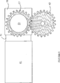
Nachfolgend wird nun auf
Bei einem bevorzugten Ausführungsbeispiel der vorliegenden Erfindung wird der Abstand der Linse von dem Bilderzeugungsarray bestimmt durch Analysieren der Bilder, die durch das Bilderzeugungsarray erzeugt werden, wenn ein Testbild auf das Bilderzeugungsarray abgebildet wird. Falls das Bild unscharf ist, wird die Position der Linse eingestellt und der Prozeß wird wiederholt, bis das Testbild scharf ist. Während dieses Prozesses wird die Linse durch das Einstellungsrad
Bei den oben beschriebenen Ausführungsbeispielen der vorliegenden Erfindung verwenden die Zahnräder Geradstirnräder, da dieser Typ von Zahnrad minimales Gleiten oder Spiel aufweist. Andere Zahnradsysteme, die geringes Gleiten oder Spiel aufweisen, können ebenfalls verwendet werden. Beispielsweise haben Zahnräder mit Zykloidenverzahnung ebenfalls minimales Gleiten und Spiel.In the above-described embodiments of the present invention, the gears use spur gears because this type of gear has minimal sliding or backlash. Other gear systems that have low glide or play can also be used. For example, cycloid gears also have minimal sliding and backlash.
Claims (6)
Applications Claiming Priority (3)
| Application Number | Priority Date | Filing Date | Title |
|---|---|---|---|
| US10/336,358 | 2003-01-03 | ||
| US10/336358 | 2003-01-03 | ||
| US10/336,358 US7215374B2 (en) | 2003-01-03 | 2003-01-03 | Camera module having geared lens barrel |
Publications (2)
| Publication Number | Publication Date |
|---|---|
| DE102004001029A1 DE102004001029A1 (en) | 2004-08-05 |
| DE102004001029B4 true DE102004001029B4 (en) | 2011-03-24 |
Family
ID=31188233
Family Applications (1)
| Application Number | Title | Priority Date | Filing Date |
|---|---|---|---|
| DE102004001029A Expired - Fee Related DE102004001029B4 (en) | 2003-01-03 | 2004-01-02 | Camera module with a toothed lens tube |
Country Status (4)
| Country | Link |
|---|---|
| US (1) | US7215374B2 (en) |
| JP (1) | JP2004212982A (en) |
| DE (1) | DE102004001029B4 (en) |
| GB (1) | GB2397394B (en) |
Families Citing this family (15)
| Publication number | Priority date | Publication date | Assignee | Title |
|---|---|---|---|---|
| EP1471730A1 (en) * | 2003-03-31 | 2004-10-27 | Dialog Semiconductor GmbH | Miniature camera module |
| US7453516B2 (en) * | 2003-06-04 | 2008-11-18 | Aptina Imaging Corporation | Flexible camera lens barrel |
| EP1648181A1 (en) | 2004-10-12 | 2006-04-19 | Dialog Semiconductor GmbH | A multiple frame grabber |
| US7598996B2 (en) * | 2004-11-16 | 2009-10-06 | Aptina Imaging Corporation | System and method for focusing a digital camera |
| CN101191892A (en) * | 2006-12-01 | 2008-06-04 | 鸿富锦精密工业(深圳)有限公司 | Automatic focusing device |
| CN101206298A (en) * | 2006-12-20 | 2008-06-25 | 鸿富锦精密工业(深圳)有限公司 | Automatic focusing device |
| CN100561275C (en) * | 2006-12-29 | 2009-11-18 | 鸿富锦精密工业(深圳)有限公司 | Camera lens module assembling and testing device and assembling test method |
| KR101180416B1 (en) | 2010-12-23 | 2012-09-10 | (주) 프렉코 | Hinge device for mobile phone |
| KR101428842B1 (en) * | 2011-11-08 | 2014-08-08 | 엘지이노텍 주식회사 | Camera module for Vehicle |
| US9513458B1 (en) * | 2012-10-19 | 2016-12-06 | Cognex Corporation | Carrier frame and circuit board for an electronic device with lens backlash reduction |
| US9746636B2 (en) | 2012-10-19 | 2017-08-29 | Cognex Corporation | Carrier frame and circuit board for an electronic device |
| USD774584S1 (en) * | 2014-01-06 | 2016-12-20 | Flir Systems, Inc. | Camera module |
| CN106291967A (en) * | 2015-05-27 | 2017-01-04 | 鸿富锦精密工业(深圳)有限公司 | Lens assembling test device |
| JP6481944B2 (en) * | 2015-09-18 | 2019-03-13 | パナソニックIpマネジメント株式会社 | Imaging device |
| CN113038120B (en) * | 2021-02-24 | 2022-07-01 | 杭州海康威视数字技术股份有限公司 | Backhaul difference determining method and device |
Citations (2)
| Publication number | Priority date | Publication date | Assignee | Title |
|---|---|---|---|---|
| EP0344806A2 (en) * | 1988-06-03 | 1989-12-06 | Asahi Kogaku Kogyo Kabushiki Kaisha | Drive mechanism for a zoom lens |
| WO2001043202A2 (en) * | 1999-12-08 | 2001-06-14 | Amkor Technology, Inc. | Molded image sensor package having lens holder |
Family Cites Families (13)
| Publication number | Priority date | Publication date | Assignee | Title |
|---|---|---|---|---|
| US3827779A (en) * | 1973-06-04 | 1974-08-06 | Bell & Howell Co | Lens focusing system |
| US3888568A (en) | 1974-06-20 | 1975-06-10 | Polaroid Corp | Multi-element lens assembly |
| JPS63314510A (en) | 1987-06-17 | 1988-12-22 | Matsushita Electric Ind Co Ltd | Lens holder |
| JPH0687091B2 (en) * | 1987-08-10 | 1994-11-02 | 松下電器産業株式会社 | Lens holding device |
| JPH0542424Y2 (en) * | 1988-06-27 | 1993-10-26 | ||
| JPH05127059A (en) * | 1991-10-30 | 1993-05-25 | Asahi Optical Co Ltd | Device for adjusting focus of variable focal distance lens for camera |
| JP3244773B2 (en) * | 1992-06-22 | 2002-01-07 | キヤノン株式会社 | Optical equipment |
| JP2901116B2 (en) * | 1992-11-30 | 1999-06-07 | 株式会社日立製作所 | Control method of autofocus device |
| US5530502A (en) * | 1995-03-13 | 1996-06-25 | Eastman Kodak Company | Camera autowind gear mechanism |
| CN1060257C (en) * | 1995-06-09 | 2001-01-03 | 李汉玉 | Cycloidal gear driving mechanism and apparatus |
| JP3736085B2 (en) * | 1997-11-26 | 2006-01-18 | コニカミノルタフォトイメージング株式会社 | Zoom lens barrel |
| JP2002062465A (en) * | 2000-08-16 | 2002-02-28 | Sony Corp | Optical component connecting device and optical module using it |
| US6954292B2 (en) * | 2000-09-13 | 2005-10-11 | Fuji Photo Film Co., Ltd. | Image scan apparatus and focus control method |
-
2003
- 2003-01-03 US US10/336,358 patent/US7215374B2/en active Active
- 2003-12-18 JP JP2003421034A patent/JP2004212982A/en active Pending
- 2003-12-22 GB GB0329633A patent/GB2397394B/en not_active Expired - Lifetime
-
2004
- 2004-01-02 DE DE102004001029A patent/DE102004001029B4/en not_active Expired - Fee Related
Patent Citations (2)
| Publication number | Priority date | Publication date | Assignee | Title |
|---|---|---|---|---|
| EP0344806A2 (en) * | 1988-06-03 | 1989-12-06 | Asahi Kogaku Kogyo Kabushiki Kaisha | Drive mechanism for a zoom lens |
| WO2001043202A2 (en) * | 1999-12-08 | 2001-06-14 | Amkor Technology, Inc. | Molded image sensor package having lens holder |
Also Published As
| Publication number | Publication date |
|---|---|
| JP2004212982A (en) | 2004-07-29 |
| DE102004001029A1 (en) | 2004-08-05 |
| US7215374B2 (en) | 2007-05-08 |
| GB2397394A (en) | 2004-07-21 |
| US20040130656A1 (en) | 2004-07-08 |
| GB2397394B (en) | 2006-07-26 |
| GB0329633D0 (en) | 2004-01-28 |
Similar Documents
| Publication | Publication Date | Title |
|---|---|---|
| DE102004001029B4 (en) | Camera module with a toothed lens tube | |
| DE102014204635B4 (en) | Lens device, camera system, and control method for the camera system | |
| DE19612643B4 (en) | TTL exposure control device | |
| DE10342526B4 (en) | camera assembly | |
| DE3049100C2 (en) | ||
| DE2407779A1 (en) | DEVICE FOR MOVING A CAMERA LENS FOR FOCUSING | |
| DE102005057511A1 (en) | Imaging device with an optical image stabilizer | |
| DE2357741C3 (en) | Photographic camera with a lens barrel axially adjustable to several discrete distance values | |
| DE3938650A1 (en) | CAMERA WITH SELECTABLE FUNCTIONS | |
| DE60204849T2 (en) | METHOD AND DEVICE FOR LOCATING THE CONNECTION CONTACTS OF ELECTRONIC COMPONENTS | |
| DE4125537C2 (en) | Method and device for automatically focusing an imaging system | |
| DE10297222T5 (en) | Angle selective filter | |
| DE2443881C3 (en) | ||
| DE2410744A1 (en) | ZOOM LENS | |
| DE3037879A1 (en) | CAMERA WITH AUTO FOCUS | |
| DE2821722C2 (en) | Device for automatic or semi-automatic focusing of the image of an object on an image plane | |
| DE102004010958A1 (en) | Device for producing a camera | |
| DE2218125C3 (en) | Data transmission device for a camera with interchangeable lenses | |
| DE2136963B2 (en) | Device for taking into account the focal length and the maximum aperture of the lenses in single-lens reflex cameras with internal measurement | |
| DE2325957B2 (en) | Angle finder with adjustable magnification system | |
| DE3503082A1 (en) | IMAGE RECORDING DEVICE | |
| DE19500507C2 (en) | Camera with lens and image carrier adjustment device and focusing method | |
| DE2204393C2 (en) | Sectional distance measuring device for opto-electronic receivers | |
| DE1959182C (en) | Optical device | |
| DE643095C (en) | Photographic 35mm camera with viewfinder chamber |
Legal Events
| Date | Code | Title | Description |
|---|---|---|---|
| OP8 | Request for examination as to paragraph 44 patent law | ||
| 8127 | New person/name/address of the applicant |
Owner name: AVAGO TECHNOLOGIES SENSOR IP (SINGAPORE) PTE. LTD. |
|
| 8127 | New person/name/address of the applicant |
Owner name: MICRON TECHNOLOGY, INC., BOISE, ID., US |
|
| R020 | Patent grant now final | ||
| R020 | Patent grant now final |
Effective date: 20110810 |
|
| R119 | Application deemed withdrawn, or ip right lapsed, due to non-payment of renewal fee | ||
| R119 | Application deemed withdrawn, or ip right lapsed, due to non-payment of renewal fee |
Effective date: 20140801 |