DE10058552B4 - operating device - Google Patents
operating device Download PDFInfo
- Publication number
- DE10058552B4 DE10058552B4 DE2000158552 DE10058552A DE10058552B4 DE 10058552 B4 DE10058552 B4 DE 10058552B4 DE 2000158552 DE2000158552 DE 2000158552 DE 10058552 A DE10058552 A DE 10058552A DE 10058552 B4 DE10058552 B4 DE 10058552B4
- Authority
- DE
- Germany
- Prior art keywords
- control surface
- operating
- operating device
- taststößel
- control
- Prior art date
- Legal status (The legal status is an assumption and is not a legal conclusion. Google has not performed a legal analysis and makes no representation as to the accuracy of the status listed.)
- Expired - Fee Related
Links
- 239000000463 material Substances 0.000 claims description 6
- 238000005516 engineering process Methods 0.000 claims description 3
- 239000004020 conductor Substances 0.000 claims description 2
- 238000000149 argon plasma sintering Methods 0.000 description 5
- 230000000087 stabilizing effect Effects 0.000 description 5
- 238000005286 illumination Methods 0.000 description 4
- 238000009434 installation Methods 0.000 description 4
- 210000003746 feather Anatomy 0.000 description 3
- 239000000523 sample Substances 0.000 description 3
- 238000011156 evaluation Methods 0.000 description 2
- 238000004519 manufacturing process Methods 0.000 description 2
- 230000001960 triggered effect Effects 0.000 description 2
- 230000015572 biosynthetic process Effects 0.000 description 1
- 239000003086 colorant Substances 0.000 description 1
- 238000004040 coloring Methods 0.000 description 1
- 230000001419 dependent effect Effects 0.000 description 1
- 238000001514 detection method Methods 0.000 description 1
- 230000005489 elastic deformation Effects 0.000 description 1
- 230000003760 hair shine Effects 0.000 description 1
- 238000001746 injection moulding Methods 0.000 description 1
- 238000003780 insertion Methods 0.000 description 1
- 230000037431 insertion Effects 0.000 description 1
- 238000002372 labelling Methods 0.000 description 1
- 238000007639 printing Methods 0.000 description 1
- 238000007493 shaping process Methods 0.000 description 1
- 238000005476 soldering Methods 0.000 description 1
- 239000012780 transparent material Substances 0.000 description 1
Images

Classifications
-
- H—ELECTRICITY
- H01—ELECTRIC ELEMENTS
- H01H—ELECTRIC SWITCHES; RELAYS; SELECTORS; EMERGENCY PROTECTIVE DEVICES
- H01H21/00—Switches operated by an operating part in the form of a pivotable member acted upon directly by a solid body, e.g. by a hand
- H01H21/02—Details
- H01H21/18—Movable parts; Contacts mounted thereon
- H01H21/22—Operating parts, e.g. handle
-
- H—ELECTRICITY
- H01—ELECTRIC ELEMENTS
- H01H—ELECTRIC SWITCHES; RELAYS; SELECTORS; EMERGENCY PROTECTIVE DEVICES
- H01H1/00—Contacts
- H01H1/58—Electric connections to or between contacts; Terminals
- H01H2001/5888—Terminals of surface mounted devices [SMD]
-
- H—ELECTRICITY
- H01—ELECTRIC ELEMENTS
- H01H—ELECTRIC SWITCHES; RELAYS; SELECTORS; EMERGENCY PROTECTIVE DEVICES
- H01H9/00—Details of switching devices, not covered by groups H01H1/00 - H01H7/00
- H01H9/18—Distinguishing marks on switches, e.g. for indicating switch location in the dark; Adaptation of switches to receive distinguishing marks
- H01H9/182—Illumination of the symbols or distinguishing marks
- H01H2009/183—Provisions for enhancing the contrast between the illuminated symbol and the background or between juxtaposed symbols
-
- H—ELECTRICITY
- H01—ELECTRIC ELEMENTS
- H01H—ELECTRIC SWITCHES; RELAYS; SELECTORS; EMERGENCY PROTECTIVE DEVICES
- H01H2221/00—Actuators
- H01H2221/008—Actuators other then push button
- H01H2221/016—Lever; Rocker
-
- H—ELECTRICITY
- H01—ELECTRIC ELEMENTS
- H01H—ELECTRIC SWITCHES; RELAYS; SELECTORS; EMERGENCY PROTECTIVE DEVICES
- H01H2221/00—Actuators
- H01H2221/036—Return force
- H01H2221/044—Elastic part on actuator or casing
-
- H—ELECTRICITY
- H01—ELECTRIC ELEMENTS
- H01H—ELECTRIC SWITCHES; RELAYS; SELECTORS; EMERGENCY PROTECTIVE DEVICES
- H01H2221/00—Actuators
- H01H2221/066—Actuators replaceable
-
- H—ELECTRICITY
- H01—ELECTRIC ELEMENTS
- H01H—ELECTRIC SWITCHES; RELAYS; SELECTORS; EMERGENCY PROTECTIVE DEVICES
- H01H2233/00—Key modules
- H01H2233/002—Key modules joined to form button rows
- H01H2233/004—One molded part
-
- H—ELECTRICITY
- H01—ELECTRIC ELEMENTS
- H01H—ELECTRIC SWITCHES; RELAYS; SELECTORS; EMERGENCY PROTECTIVE DEVICES
- H01H9/00—Details of switching devices, not covered by groups H01H1/00 - H01H7/00
- H01H9/18—Distinguishing marks on switches, e.g. for indicating switch location in the dark; Adaptation of switches to receive distinguishing marks
- H01H9/182—Illumination of the symbols or distinguishing marks
Landscapes
- Push-Button Switches (AREA)
Abstract
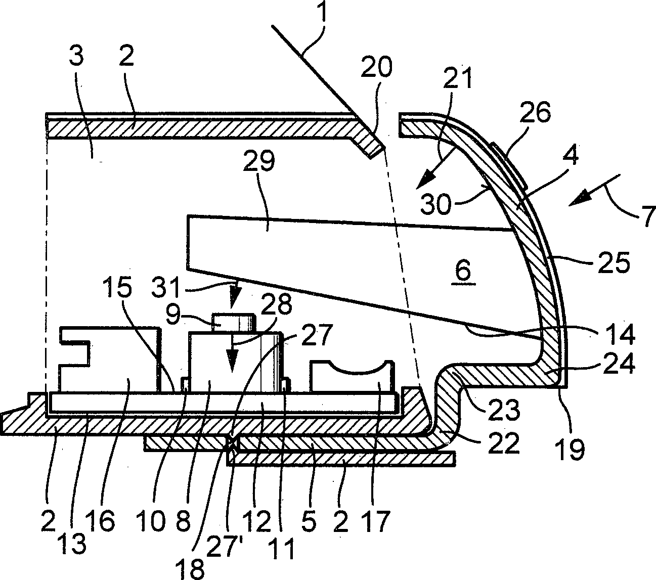
Bedienvorrichtung mit einer Bedienfläche, wobei an der einem Benutzer abgewandten Seite der Bedienfläche ein Taststößel angeordnet ist und wobei die Bedienfläche federnd gelagert ist, wobei seitlich zu einer Oberfläche (14) des Taststößels (6) ein Tastschalter (8) angeordnet ist; und wobei der Tastschalter (8) durch den Taststößel (6) schaltbar ist, dadurch gekennzeichnet, dass die Bedienfläche (4) in einen Grundkörper (2) oder einen Rahmen (1) einschiebbar und verrastbar ist.Operating device with a control surface, wherein on the side facing away from a user of the control surface a Taststößel is arranged and wherein the control surface is resiliently mounted, wherein the side of a surface (14) of the Taststößels (6) a push-button switch (8) is arranged; and wherein the key switch (8) by the Taststößel (6) is switchable, characterized in that the control surface (4) in a base body (2) or a frame (1) can be inserted and latched.
Description
Stand der TechnikState of the art
Die Erfindung geht aus von einer Bedienvorrichtung nach der Gattung des Hauptanspruchs. Es sind schon Bedienvorrichtungen in der Form von Druck- beziehungsweise Tastschaltern bekannt, bei denen auf einer einem Benutzer abgewandten Seite eines Bedienelements eine elektrische Kontaktierung angeordnet ist, so dass zwei Kontakte einer Leiterplatte miteinander elektrisch leitend verbunden werden. Ein solcher Schalter ist z. B. aus der
Aus der
Aus der
Aus der
Vorteile der ErfindungAdvantages of the invention
Die erfindungsgemäße Bedienvorrichtung mit den Merkmalen des Hauptanspruchs hat demgegenüber den Vorteil, dass durch die seitliche Anordnung eines Tastschalters zu einem Taststößel der Bedienvorrichtung ein Schaltweg senkrecht zu einer Bedienungs- und Bewegungsrichtung einer Bedienfläche der Bedienvorrichtung ermöglicht und damit der erforderliche Bauraum reduziert werden kann, indem der Taststößel seitlich auf einen Tastschalter bewegt wird. Hierdurch wird insbesondere die für die Bedienvorrichtung erforderliche Einbautiefe stark reduziert, ohne dass auf eine für einen Benutzer sichtbare, herkömmliche Bedienfläche verzichtet werden muss. Durch eine federnde Lagerung der Bedienfläche ist dabei eine selbständige Rückstellung der Bedienfläche nach einer Bedienung, also insbesondere nach einer Druckausübung auf die Bedienfläche durch einen Benutzer, in eine Ausgangsposition gewährleistet. Eine Flächenbegrenzung der erfindungsgemäßen Bedienvorrichtung ist durch die Größe der verwendeten Bedienfläche gegeben. Die Ausgestaltung der Bedienfläche ermöglicht es, eine ungefähr senkrecht auf die Bedienfläche auftreffende Kraftwirkung in eine ungefähr rechtwinklig zu dieser auftreffenden Kraft wirkenden Bewegungsrichtung des Taststößels umzuwandeln, so dass eine Auswertung mittels eines seitlich zu dem Taststößel angeordneten Tastschalters erfolgen kann.The operating device according to the invention with the features of the main claim has the advantage that allows a switching path perpendicular to an operating and moving direction of a control surface of the operating device by the lateral arrangement of a push-button to a Taststößel the operating device and thus the required space can be reduced by the Taststößel is moved laterally on a push-button. As a result, in particular the installation depth required for the operating device is greatly reduced, without having to forego a visible for a user, conventional control surface. By a resilient mounting of the control surface is an independent provision of the control surface after an operation, ie in particular after a pressure on the control surface by a user, guaranteed in a starting position. A surface boundary of the operating device according to the invention is given by the size of the control surface used. The design of the control surface makes it possible to convert a force acting approximately perpendicular to the operating force in a force acting approximately at right angles to this impinging force direction of the Taststößels, so that an evaluation can be done by means of a laterally arranged to the Taststößel key switch.
Durch die in den Unteransprüchen aufgeführten Maßnahmen sind vorteilhafte Weiterbildungen und Verbesserungen der in dem Hauptanspruch angegebenen Bedienvorrichtung möglich. Besonders vorteilhaft ist, dass der Rand der Bedienfläche federnd ausgeführt und in eine Halterung eingeführt ist, so dass kein zusätzliches Federelement für die Bedienvorrichtung erforderlich ist, sondern vorzugsweise ein an die Bedienfläche unmittelbar angeformter Rand einen Federbereich bildet. Hierdurch kann auf einen Montageschritt für ein Federelement verzichtet werden, insbesondere bei einer einstückigen Ausführung von Bedienfläche und Federbereich The measures listed in the dependent claims advantageous refinements and improvements of the main claim operating device are possible. It is particularly advantageous that the edge of the control surface is resilient and inserted into a holder, so that no additional spring element for the operating device is required, but preferably forms a spring surface formed directly on the control surface edge. This makes it possible to dispense with an assembly step for a spring element, in particular in a one-piece design of control surface and spring area
Weiterhin ist vorteilhaft, einen Anschlag für die Bedienfläche oder den Taststößel vorzusehen, um die Bewegung der Bedienfläche zu begrenzen, damit eine mögliche Beschädigung des Tastschalters durch eine zu weite Bewegung bzw. eine zu große Druckbeanspruchung vermieden wird.Furthermore, it is advantageous to provide a stop for the control surface or the Taststößel to limit the movement of the control surface, so that a possible damage to the pushbutton is avoided by too far movement or too much compressive stress.
Weiterhin ist vorteilhaft, den Taster auf einer Leiterplatte anzuordnen, da hierdurch eine einfache elektrische Kontaktierung des Tasters möglich ist. Besonders vorteilhaft ist eine Ausbildung des Tasters als ein in SMD-Technik auf die Leiterplatte aufbringbarer Taster, da auf diese Weise eine besonders schnelle und einfache Montage des Tasters maschinell möglich ist.Furthermore, it is advantageous to arrange the probe on a circuit board, as this is a simple electrical contacting of the probe is possible. Particularly advantageous is a design of the probe as an attachable in SMD technology on the circuit board button, as in this way a particularly quick and easy installation of the button is mechanically possible.
Weiterhin ist vorteilhaft, eine Lichtquelle auf der Leiterplatte anzubringen, die der Hinterleuchtung der Bedienfläche dient. Hierbei ist insbesondere vorteilhaft, den Taststößel und/oder die Bedienfläche zumindest teilweise aus lichtleitendem Material zu fertigen, da das Licht ausgehend von der Lichtquelle durch den Taststößel zu der Bedienfläche oder direkt zu der Bedienfläche geleitet werden kann und hiermit eine Beleuchtung der Bedienfläche möglich ist, so dass auch eine Bedienung bei Dunkelheit erfolgen kann.Furthermore, it is advantageous to attach a light source on the circuit board, which serves the backlighting of the control surface. In this case, it is particularly advantageous for the feeler plunger and / or the operating surface to be at least partially made of light-conducting material finished, since the light can be passed from the light source by the Taststößel to the control surface or directly to the control surface and hereby an illumination of the control surface is possible, so that an operation can be done in the dark.
Weiterhin ist vorteilhaft, das lichtleitende Material einzufärben, da hierdurch eine farbige Beleuchtung möglich ist, auch ohne eine farbige Lichtquelle zu verwenden. Hierdurch können bei der Verwendung gleichartiger Lichtquellen unterschiedliche Beleuchtungsfarben verschiedener, nebeneinander angeordneter Bedienvorrichtungen realisiert werden.Furthermore, it is advantageous to color the photoconductive material, as a result, a colored lighting is possible, even without using a colored light source. As a result, when using similar light sources, different illumination colors of different, adjacently arranged operating devices can be realized.
Erfindungsgemäß ist es vorteilhaft, die Bedienfläche in einem Rahmen verrastbar auszuführen, da hierdurch eine einfache Montage durch bloßes Aufstecken der Bedienfläche auf den Rahmen möglich ist. Ferner ist hierdurch möglich, die Bedienfläche, z. B. zum Auswechseln der Leiterplatte, des Tastschalters oder der Lichtquelle auf einfache Weise zu öffnen und die Leiterplatte zu entnehmen.According to the invention it is advantageous to perform the control surface latched in a frame, as this is a simple installation by merely plugging the control surface on the frame is possible. Furthermore, this is possible, the operating surface, for. B. to replace the circuit board, the key switch or the light source to easily open and remove the circuit board.
Weiterhin ist vorteilhaft, dass hierbei durch ein einfaches Aufstecken der Bedienfläche auf einen Grundkörper eine einfache Montage möglich ist.Furthermore, it is advantageous that in this case a simple assembly is possible by simply plugging the control surface onto a base body.
Weiterhin ist vorteilhaft, die erfindungsgemäße Bedienvorrichtung in einem Kraftfahrzeug zu verwenden, da insbesondere in Fahrzeugen der zur Verfügung stehende Bauraum eng begrenzt ist und somit die Verwendung einer erfindungsgemäßen Bedienvorrichtung eine kompakte Bauweise ermöglicht.Furthermore, it is advantageous to use the operating device according to the invention in a motor vehicle, since in vehicles in particular the available space is limited and thus the use of an operating device according to the invention enables a compact design.
Zeichnungdrawing
Ein Ausführungsbeispiel der Erfindung ist in der Zeichnung dargestellt und in der nachfolgenden Beschreibung näher erläutert. Es zeigen
Beschreibung des AusführungsbeispielsDescription of the embodiment
In der
Die Bedienfläche
Über den Steckkontakt
Durch die Lichtquelle
Bei der Fertigung der erfindungsgemäßen Bedienvorrichtung wird zunächst die mit den elektrischen Bauteilen
Anstelle der anhand der
In der
Claims (13)
Priority Applications (1)
| Application Number | Priority Date | Filing Date | Title |
|---|---|---|---|
| DE2000158552 DE10058552B4 (en) | 2000-11-24 | 2000-11-24 | operating device |
Applications Claiming Priority (1)
| Application Number | Priority Date | Filing Date | Title |
|---|---|---|---|
| DE2000158552 DE10058552B4 (en) | 2000-11-24 | 2000-11-24 | operating device |
Publications (2)
| Publication Number | Publication Date |
|---|---|
| DE10058552A1 DE10058552A1 (en) | 2002-05-29 |
| DE10058552B4 true DE10058552B4 (en) | 2011-03-17 |
Family
ID=7664632
Family Applications (1)
| Application Number | Title | Priority Date | Filing Date |
|---|---|---|---|
| DE2000158552 Expired - Fee Related DE10058552B4 (en) | 2000-11-24 | 2000-11-24 | operating device |
Country Status (1)
| Country | Link |
|---|---|
| DE (1) | DE10058552B4 (en) |
Families Citing this family (4)
| Publication number | Priority date | Publication date | Assignee | Title |
|---|---|---|---|---|
| DE10251539B4 (en) * | 2002-11-05 | 2006-10-19 | Medion Ag | switch |
| DE10334623A1 (en) * | 2003-07-29 | 2005-03-03 | Siemens Ag | holder |
| DE102009051617B3 (en) * | 2009-11-02 | 2011-04-28 | Pas Deutschland Gmbh | Button for an operating arrangement, as well as operating arrangement and household appliance |
| DE102014221960A1 (en) | 2014-10-28 | 2016-04-28 | Robert Bosch Gmbh | Switching arrangement with a spring-trained button |
Citations (4)
| Publication number | Priority date | Publication date | Assignee | Title |
|---|---|---|---|---|
| US4136270A (en) * | 1977-03-24 | 1979-01-23 | Gte Automatic Electric Laboratories Incorporated | Actuator for pushbutton switch |
| DE4001871A1 (en) * | 1989-01-27 | 1990-08-09 | Clarion Co Ltd | MULTI-STAGE PUSH BUTTON DEVICE AND METHOD FOR THEIR PRODUCTION |
| JPH1064138A (en) * | 1996-08-26 | 1998-03-06 | Mitsubishi Electric Corp | Push button device |
| DE19704253C2 (en) * | 1997-02-05 | 2000-01-20 | Hella Kg Hueck & Co | Operating unit for a motor vehicle component, in particular for the control unit of a motor vehicle air conditioning system |
-
2000
- 2000-11-24 DE DE2000158552 patent/DE10058552B4/en not_active Expired - Fee Related
Patent Citations (4)
| Publication number | Priority date | Publication date | Assignee | Title |
|---|---|---|---|---|
| US4136270A (en) * | 1977-03-24 | 1979-01-23 | Gte Automatic Electric Laboratories Incorporated | Actuator for pushbutton switch |
| DE4001871A1 (en) * | 1989-01-27 | 1990-08-09 | Clarion Co Ltd | MULTI-STAGE PUSH BUTTON DEVICE AND METHOD FOR THEIR PRODUCTION |
| JPH1064138A (en) * | 1996-08-26 | 1998-03-06 | Mitsubishi Electric Corp | Push button device |
| DE19704253C2 (en) * | 1997-02-05 | 2000-01-20 | Hella Kg Hueck & Co | Operating unit for a motor vehicle component, in particular for the control unit of a motor vehicle air conditioning system |
Also Published As
| Publication number | Publication date |
|---|---|
| DE10058552A1 (en) | 2002-05-29 |
Similar Documents
| Publication | Publication Date | Title |
|---|---|---|
| DE102007023944B4 (en) | pressure switch | |
| EP2057738B1 (en) | Control device for a household appliance comprising at least one capacitive sensor key | |
| DE102006041797B4 (en) | Button and hollow fiber optic mechanism and corresponding arrangement | |
| DE19704253C2 (en) | Operating unit for a motor vehicle component, in particular for the control unit of a motor vehicle air conditioning system | |
| WO2007053966A2 (en) | Integrated switch or integrated button | |
| EP2001699B1 (en) | Multifunctional display and operating device in a motor vehicle | |
| DE102013001876A1 (en) | Operating device with optical finger navigation module for a steering wheel | |
| DE102004019304A1 (en) | Operating device with a touch switch | |
| DE2934764A1 (en) | PRESSURE CONTROL SWITCH | |
| WO2018234360A1 (en) | USER CONTROL DEVICE OF MOTOR VEHICLE | |
| DE4411721A1 (en) | Illuminated switch | |
| DE10058552B4 (en) | operating device | |
| EP1385188B1 (en) | Electrical switchgear | |
| DE3133134A1 (en) | Electrical switch, especially for motor vehicles | |
| DE102013215719B3 (en) | Buttonmodul | |
| WO1996019713A1 (en) | Indicator | |
| EP1243816A2 (en) | Range selection apparatus for an automatic transmission | |
| EP0587056A1 (en) | Rocker keyswitch | |
| DE9102919U1 (en) | Key layout | |
| EP0148437B1 (en) | Key cap for a keyboard mounted in a housing | |
| DE19627294A1 (en) | Rocker switch | |
| EP1443533B1 (en) | Electrical switches | |
| DE102011077899A1 (en) | Capacitive control device for a household appliance and household appliance | |
| DE19714651A1 (en) | Monostable switchgear in form of toggle switch e.g for motor vehicles | |
| DE19920547C1 (en) | Electric steering column switch for automobile has switch piece controlled by manual operating element incorporating second switch mechanism with flexible connections between their stationary contacts |
Legal Events
| Date | Code | Title | Description |
|---|---|---|---|
| 8110 | Request for examination paragraph 44 | ||
| R020 | Patent grant now final |
Effective date: 20110703 |
|
| R119 | Application deemed withdrawn, or ip right lapsed, due to non-payment of renewal fee |