EP1443533B1 - Electrical switches - Google Patents
Electrical switches Download PDFInfo
- Publication number
- EP1443533B1 EP1443533B1 EP04001931A EP04001931A EP1443533B1 EP 1443533 B1 EP1443533 B1 EP 1443533B1 EP 04001931 A EP04001931 A EP 04001931A EP 04001931 A EP04001931 A EP 04001931A EP 1443533 B1 EP1443533 B1 EP 1443533B1
- Authority
- EP
- European Patent Office
- Prior art keywords
- housing
- actuating member
- axle
- snap
- electric switch
- Prior art date
- Legal status (The legal status is an assumption and is not a legal conclusion. Google has not performed a legal analysis and makes no representation as to the accuracy of the status listed.)
- Expired - Lifetime
Links
- 230000033001 locomotion Effects 0.000 claims description 15
- 239000002184 metal Substances 0.000 claims description 3
- 239000013307 optical fiber Substances 0.000 claims 1
- 230000003014 reinforcing effect Effects 0.000 claims 1
- 210000002414 leg Anatomy 0.000 description 21
- 230000006378 damage Effects 0.000 description 8
- 208000027418 Wounds and injury Diseases 0.000 description 5
- 208000014674 injury Diseases 0.000 description 5
- 238000011161 development Methods 0.000 description 3
- 230000018109 developmental process Effects 0.000 description 3
- 238000007654 immersion Methods 0.000 description 3
- 230000009471 action Effects 0.000 description 2
- 238000004140 cleaning Methods 0.000 description 2
- 238000004519 manufacturing process Methods 0.000 description 2
- 230000007480 spreading Effects 0.000 description 2
- 206010060820 Joint injury Diseases 0.000 description 1
- 208000016593 Knee injury Diseases 0.000 description 1
- 238000011109 contamination Methods 0.000 description 1
- 230000001419 dependent effect Effects 0.000 description 1
- 238000005286 illumination Methods 0.000 description 1
- 238000001746 injection moulding Methods 0.000 description 1
- 238000009434 installation Methods 0.000 description 1
- 230000003993 interaction Effects 0.000 description 1
- 239000000463 material Substances 0.000 description 1
- 239000007858 starting material Substances 0.000 description 1
- 210000003813 thumb Anatomy 0.000 description 1
- 210000000689 upper leg Anatomy 0.000 description 1
Images


Classifications
-
- G—PHYSICS
- G05—CONTROLLING; REGULATING
- G05G—CONTROL DEVICES OR SYSTEMS INSOFAR AS CHARACTERISED BY MECHANICAL FEATURES ONLY
- G05G1/00—Controlling members, e.g. knobs or handles; Assemblies or arrangements thereof; Indicating position of controlling members
- G05G1/08—Controlling members for hand actuation by rotary movement, e.g. hand wheels
- G05G1/087—Controlling members for hand actuation by rotary movement, e.g. hand wheels retractable; Flush control knobs
-
- B60K35/10—
-
- B—PERFORMING OPERATIONS; TRANSPORTING
- B60—VEHICLES IN GENERAL
- B60Q—ARRANGEMENT OF SIGNALLING OR LIGHTING DEVICES, THE MOUNTING OR SUPPORTING THEREOF OR CIRCUITS THEREFOR, FOR VEHICLES IN GENERAL
- B60Q1/00—Arrangement of optical signalling or lighting devices, the mounting or supporting thereof or circuits therefor
- B60Q1/0076—Switches therefor
-
- B—PERFORMING OPERATIONS; TRANSPORTING
- B60—VEHICLES IN GENERAL
- B60R—VEHICLES, VEHICLE FITTINGS, OR VEHICLE PARTS, NOT OTHERWISE PROVIDED FOR
- B60R21/00—Arrangements or fittings on vehicles for protecting or preventing injuries to occupants or pedestrians in case of accidents or other traffic risks
- B60R21/02—Occupant safety arrangements or fittings, e.g. crash pads
- B60R21/09—Control elements or operating handles movable from an operative to an out-of-the way position, e.g. pedals, switch knobs, window cranks
-
- H—ELECTRICITY
- H01—ELECTRIC ELEMENTS
- H01H—ELECTRIC SWITCHES; RELAYS; SELECTORS; EMERGENCY PROTECTIVE DEVICES
- H01H3/00—Mechanisms for operating contacts
- H01H3/02—Operating parts, i.e. for operating driving mechanism by a mechanical force external to the switch
- H01H3/08—Turn knobs
-
- B60K2360/139—
-
- H—ELECTRICITY
- H01—ELECTRIC ELEMENTS
- H01H—ELECTRIC SWITCHES; RELAYS; SELECTORS; EMERGENCY PROTECTIVE DEVICES
- H01H3/00—Mechanisms for operating contacts
- H01H3/02—Operating parts, i.e. for operating driving mechanism by a mechanical force external to the switch
- H01H2003/026—Operating parts, i.e. for operating driving mechanism by a mechanical force external to the switch specially adapted to avoid injury to occupants of a car during an accident
-
- H—ELECTRICITY
- H01—ELECTRIC ELEMENTS
- H01H—ELECTRIC SWITCHES; RELAYS; SELECTORS; EMERGENCY PROTECTIVE DEVICES
- H01H3/00—Mechanisms for operating contacts
- H01H3/02—Operating parts, i.e. for operating driving mechanism by a mechanical force external to the switch
- H01H3/08—Turn knobs
- H01H2003/085—Retractable turn knobs, e.g. flush mounted
-
- H—ELECTRICITY
- H01—ELECTRIC ELEMENTS
- H01H—ELECTRIC SWITCHES; RELAYS; SELECTORS; EMERGENCY PROTECTIVE DEVICES
- H01H19/00—Switches operated by an operating part which is rotatable about a longitudinal axis thereof and which is acted upon directly by a solid body external to the switch, e.g. by a hand
- H01H2019/008—Switches operated by an operating part which is rotatable about a longitudinal axis thereof and which is acted upon directly by a solid body external to the switch, e.g. by a hand with snap mounting of rotatable part on fixed part, e.g. rotor on stator, operating knob on switch panel
Definitions
- the invention relates to an electrical switch according to the preamble of patent claim 1.
- Electric switches are used in the motor vehicle for various functions.
- an actuatable in the manner of a rotary switch electrical switch is used in a light control unit for switching the automotive lighting.
- Such an electrical switch is known for example from DE 43 28 030 A1.
- This switch has a housing and a projecting from the housing actuator.
- the contact system In the housing is the contact system, which is switchable by the operator by means of the actuator.
- a disadvantage of this known switch is the risk of injury to the actuator, in particular when using the switch in a motor vehicle.
- a rotary switch for a motor vehicle in such a way that the actuator is at least partially retractable in the housing by the action of a force exceeding a threshold.
- This is achieved by the actuator is mounted on springs or holding parts with predetermined breaking points. Due to force in an accident break the springs or the holding parts whereby the actuator is immersed in the housing of the switch, so that the risk of injury to the user of the motor vehicle is reduced.
- US Pat. No. 4,051,916 A describes a switch built into the dashboard of a motor vehicle according to the preamble of claim 1, in which an actuating member projects out of the dashboard through an opening.
- the switch has a housing which is held by a flange and springs in the instrument panel.
- the invention has for its object to further develop the electrical switch with reduced risk of injury such that its unintentional destruction is avoided and the switch is designed simply.
- the electrical switch according to the invention is designed such that the actuating member is at least partially retractable in the housing, wherein the recessed actuator in the housing can be moved out of the housing again by a pulling force in the opposite direction to the sinking.
- the inadvertent sinking of the actuator in the housing does not lead to the destruction or damage of the switch.
- the actuator cooperates with a spring element in the housing or with snap and / or snap hooks.
- the actuator is held in the protruding from the housing position, but the free rotation of the actuator is given to switch the contact system.
- the spring element or the snap and / or latching hooks when the threshold force is exceeded, the actuating member free, so that it is retractable in the housing.
- the switch when used to switch the lights on a motor vehicle, it may be a rotary switch in the manner of a rotary latch.
- the actuator for example by means of a shaft, an axle o. The like., Rotatably mounted in the housing, and the contact system is switched by a rotational movement of the actuator.
- the actuating member is then movable in the axial direction with respect to the rotational movement, in particular approximately perpendicular to the surface of the housing, on which the actuating member protrudes, for sinking into the housing.
- the axial retractability of the actuator provides easy design options of the switch.
- the sunken actuator is subsequently moved out of the housing manually again, then it assumes again its original position projecting out of the housing. Conveniently, it is then held in this position again.
- the actuator can also be deliberately sunk by the user when the switch is not needed.
- a spring element is fixed with one end in the housing and acts with its other free end with the actuator to the holder together.
- Such a spring element can be further improved in terms of the exercise of symmetrical holding forces in that this is designed in the manner of a roughly U-shaped leg spring.
- the leg spring is attached to the base of the U in the housing. Furthermore, the two free legs of the U engage under exercise of an elastic clamping force in a groove located on the actuator. For reasons of space and if necessary, the legs of the leg spring can be bent.
- the actuating member has a shaft arranged in the housing, an axis o. The like. On. The shaft or the axis engages a rotor actuating the contact system in such a way that, on the one hand, the rotor is rotatable by means of the actuating member and, on the other hand, the shaft or the axis is axially displaceable against the rotor.
- the groove for receiving the legs of the leg spring is located on the shaft or on the axis.
- the rotor is rotatably mounted in a holder located in the housing. If it is a three-starter switch, the rotor can interact with the aid of a spring-loaded plunger with a latching cam for fixing the latching positions.
- the shaft or the axis of the actuator is mounted in a sleeve-like approach to a holding part in the housing.
- the legs of the leg spring protrude through an opening in the holding part, whereby an engagement of the legs is made possible in the groove on the shaft or the axis.
- the switch according to the invention is particularly suitable for arrangement in an operating unit in the manner of a control unit in the motor vehicle, for example in a lighting control unit for switching the vehicle lighting.
- actuators for further switches for potentiometers o. The like.
- actuators in addition to the rotary switching, which is effected by means of the retractable actuator, further switching functions can be actuated.
- a variety of different switching functions in a compact unit is possible.
- the operating unit is configured as a type of control unit for the motor vehicle, it is also appropriate to arrange a printed circuit board in the housing for receiving the contact systems for the electrical switches, for the potentiometers or the like.
- On the circuit board is an electronics, such as a microprocessor, for processing the switching signals. If desired, the electronics may generate bus signals corresponding to the switching signals.
- the housing is connected to the printed circuit board in electrical connection for the bus system arranged.
- LEDs on the circuit board for lighting symbols, displays o. The like.
- On the actuators and / or on the housing The light emitted by the light emitting diode can be guided via appropriate light guide to the actuators and / or the housing.
- Such a configuration provides a modular unit that is to be mounted in a simple manner in the motor vehicle, for example, merely by plugging it onto the bus system.
- the snap and / or snap hooks are in a sleeve-like approach in the housing.
- the axis or the shaft is guided in the sleeve-like approach and rotatably held by means of the snap and / or latching hook in the position in which the actuator protrudes from the housing.
- the snap-in and / or snap-in hooks expediently engage in a groove on the axle or on the shaft.
- the spring element for retractable mounting of the actuator is made of metal.
- snap-in and / or snap-in hooks it is sufficient in general that they consist of plastic. Since the housing is also made of plastic by injection molding, then the snap and / or snap hooks can be integrally molded into the sleeve-like approach in a simple and cost-effective manner in the manufacture of the housing. At the same time, the sleeve-shaped approach can be provided in the manufacture of the housing with stiffening ribs.
- the snap and / or snap hooks are arranged in such a way inside the sleeve-shaped projection that a possibility of movement is given approximately transverse to the axial direction to their Aufspssen stresses.
- a stop may be located on the axis, so that the movement of the axis is limited in the axial direction.
- the advantages achieved by the invention are in particular that in a collision of the vehicle user with the switch, the actuator is immersed in the housing of the switch, so that a consequent injury to the vehicle user, such as a knee injury, is largely prevented.
- a consequent injury to the vehicle user such as a knee injury
- an improved design of the vehicle interior can be achieved in this way.
- the inventive design no biased plastic elements in the housing, for example by spring elements required and also leads to no permanent application of force, for example by spring forces in the actuator or in other plastic components of the housing. This ensures a long life of the switch.
- variable immersion and retraction forces for the actuator can be realized, which, however, on the other hand do not affect the rotational feel for the user.
- a simple installation of the switch is given, since no biasing forces of spring elements must be applied and the assembly is approximately perpendicular to the sinking direction.
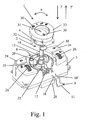
- Fig. 1 designed as a control unit light control unit 1 is shown for a motor vehicle in a partial exploded view.
- the light control unit 1 comprises an electrical switch 2 for switching the illumination of the motor vehicle.
- the light control unit 1 has a housing 3, from which protrudes an actuator 4 for operating the electrical switch 2 by the user.
- the housing 3 is still a visible in Fig. 4 contact system 5, which is encapsulated to prevent contamination.
- the contact system 5 is switchable by means of the actuating member 4.
- the actuator 4 is so designed that by the action of a force exceeding a threshold force on the actuator 4, this at least partially in the housing 3 is retractable. As useful for automotive applications, it has been found that the threshold for the force is about 300 to 400 Newton.
- the electrical switch 2 is a rotary latching switch, in which the actuating member 4 is rotatably mounted in the housing 3.
- the trained in the manner of a knob actuator 4 is surrounded by a diaphragm 33.
- the contact system 5 is thus switched by a manual rotational movement of the actuator 4 according to arrow 6 by the user.
- the actuating member 4 a arranged in the housing 3 shaft 14 and an axis 14, wherein the shaft 14 engages a visible in Fig. 3 rotor 15 such that the rotor 15 is rotatable by means of the actuating member 4.
- the rotor 15 is in turn rotatably mounted in a housing 3 located in the holder 17 and acts by means of a spring-loaded plunger 18 with a latching curve 19 in the holder 17 for fixing the locking positions together.
- the rotor 15 in turn actuates the contact system 5 by means of a projection 16 which engages in a visible in Fig. 4 receptacle 36 on the contact system 5.
- the shaft 14 is mounted on the actuating member 4 in a sleeve-like projection 20 on a holding part 35 in the housing 3.
- the actuating member 4 is now in the axial direction corresponding to the arrow 7 with respect to the rotational movement, and thus approximately perpendicular to the surface 8 of the housing 3, on which the actuator 4 protrudes, for sinking into the housing 3 movable.
- the shaft 14 is axially displaceable against the rotor 15 by the sleeve-shaped shaft 14 a Wave 21 engages over the rotor 15, as can be seen from the two FIGS. 1 and 3.
- the shaft 21 and the sleeve-shaped shaft 14 are designed similarly profiled in the rest, in order to allow rotation of the rotor 15 by means of the actuator 4 despite the axial displaceability of the shaft 14. If the actuator 4 recessed in the housing 3, so this can be moved out of the housing 3 again by a tensile force applied by the user in the opposite direction to the sinking according to the arrow 7 '. The movement in the axial direction according to arrow 7 'then takes place until the actuator 4 returns to its original, protruding from the housing 3 position in which the actuator 4 is then held.
- a spring element 9 is fixed with one end in the housing 3 according to the first embodiment shown in FIG. With its other free end, the spring element 9 cooperates with the actuating member 4.
- the actuating member 4 is held in the protruding from the housing 3 position, wherein the actuating member 4 is freely rotatable at the same time for switching the contact system 5.
- the spring element 9 releases the actuating member 4 when the threshold force is exceeded, so that it can dip into the housing 3.
- the spring element 9 is designed in the manner of an approximately U-shaped leg spring.
- the leg spring 9 is attached to the base 11 of the U to latching hooks 12 which are located on the holding part 35 in the housing 3 verclipsend.
- the two free legs 10, 10 'of the U's of the leg spring 9 extend approximately perpendicular to the axial direction 7, 7' and project through an opening 22 into the holding part 35.
- the legs 10, 10 'rest on the holding part 35 and engage in the holding part 35 in a groove 13 on the actuating member 4, namely on the shaft 14 and visible in FIG. 6, by exerting an elastic clamping force. Due to this clamping force, the actuator 4 is held in its protruding from the housing 3 position.
- the compact arrangement half in the housing 3, the legs 10, 10 ' may be provided with a bend 37, as shown in Fig. 6.
- the groove 13 encircling the shaft 14 is provided with a slope in the manner of an inclined plane.
- the threshold value for the immersion force can thus be varied as desired.
- a variable immersion and retraction force for the actuator 4 can be realized by a modified geometry of the groove 13 and / or spring force of the legs 10, 10 'and / or choice of material for the spring element 9. It should be emphasized, however, that the feel of the user felt for the rotation of the actuator 4 by the spring element 9 remains essentially unaffected.
- further switches with contact systems 23 may be arranged in and / or on the housing 3 of the light control unit 1, for example in order to switch the parking lights on the motor vehicle.
- the actuators 24 for the contact systems 23 are designed as push buttons. Likewise, these actuators may be formed in the manner of rockers, which is not shown further.
- visible potentiometer 25 for example, for headlamp leveling of the motor vehicle and / or a dimming function of the light control unit 1.
- the potentiometer 25 are operated by knurled wheels 26 as actuators by the user.
- controls in the light control unit 1 may be arranged so that other other switching functions in addition to the rotation, which can be effected by means of the actuator 4, and the aforementioned switching functions are actuated by the user.
- the housing 3 consists of an upper part 38 and a lower part 39, which are interconnected by screws 40.
- a printed circuit board 27 is arranged for receiving the at least one contact system 5. If available, there are expediently also the other contact systems 23 and The potentiometer 25 and / or the other electrical / electronic components on the printed circuit board 27. If desired, on the circuit board 27 electronics, such as a microprocessor, for processing the switching signals of the contact systems 5, 23 and the potentiometer 25 and optionally for generating bus signals located.
- a standing with the circuit board 27 via connecting pins 34 in electrical connection electrical connection 28 is arranged for a bus system.
- the switching signals of the contact systems 5, 23 and the potentiometer 25 can also be forwarded directly via the terminal 28 to a control device for automotive lighting, so that in this case can be dispensed with a corresponding electronics for processing the switching signals in the light control unit 1 ,
- a control device for automotive lighting so that in this case can be dispensed with a corresponding electronics for processing the switching signals in the light control unit 1
- visible on the circuit board 27 in Fig. 4 visible light emitting diodes 29, 29 'for illuminating shown in Fig. 1 symbols 30, 31 o.
- the like On the actuators 4, 24, 26 and / or on the housing 3 and / or at the aperture 33 to allow the user an appropriate orientation.
- the light emitted by the light-emitting diodes 29 can be guided via light-guiding elements 32 to the associated symbols 30 or displays 31.
- a light control unit 1 according to a further, second exemplary embodiment is shown in a perspective view in FIG. 7.
- this light control unit 1 no spring element 9 is used, but otherwise it is designed substantially the same as that of the first embodiment, so that here also for clarity, Figs. 2 to 4 can be used.
- the spring element 9 are in this further embodiment in the sleeve-like projection 20 of the housing 3 snap and / or latching hooks 41, as can be seen with reference to FIG. 8 or 9, to the actuator 4 in the protruding from the housing 3 position hold.
- the snap-in and / or snap-in hooks 41 engage in a groove 42 visible in FIG. 10 on the axis 14.
- a groove 42 visible in FIG. 10 on the axis 14.
- the groove 42 is designed for the purpose of adjusting the threshold value as a one-sided inclined plane.
- the spring element 9 shown in Fig. 5 is suitably made of metal.
- the visible in Fig. 9 snap and / or snap hooks 41 are made of plastic. Since the housing 3 is likewise made of plastic, the snap-in and / or latching hooks 41 can be integrally molded onto the sleeve-like attachment 20 when the upper part 38 of the housing 3 is produced.
- the snap and / or snap hooks 41 are, as can be seen with reference to FIG. 9, arranged in the interior of the sleeve-shaped projection 20 that a possibility of movement in approximately transverse to the axial direction 7, 7 'is given to the Aufsp Soniana the snap - And / or locking hooks 41 to allow.
- On the axis 14 is a stop 43, as can be seen in Fig. 10, which serves to limit the movement of the axis 14 in the axial direction 7, 7 '.
- the sleeve-shaped projection 20 is provided with stiffening ribs 44 located in the housing 3.
- the invention is not limited to the described and illustrated embodiment. Rather, it also encompasses all expert developments within the scope of the invention defined by the claims. Thus, the invention can not only be used on electrical switches for motor vehicles, but also on switches with a retractable actuator for household appliances, machine tools, power tools o. The like. Use find.
Abstract
Description
Die Erfindung betrifft einen elektrischen Schalter nach dem Oberbegriff des Patentanspruchs 1.The invention relates to an electrical switch according to the preamble of
Elektrische Schalter werden im Kraftfahrzeug für verschiedene Funktionen verwendet. Beispielsweise wird ein in der Art eines Drehschalters betätigbarer elektrischer Schalter in einer Lichtbedieneinheit zum Schalten der Kraftfahrzeugbeleuchtung eingesetzt.Electric switches are used in the motor vehicle for various functions. For example, an actuatable in the manner of a rotary switch electrical switch is used in a light control unit for switching the automotive lighting.
Ein solcher elektrischer Schalter ist beispielsweise aus der DE 43 28 030 A1 bekannt. Dieser Schalter besitzt ein Gehäuse sowie ein aus dem Gehäuse ragendes Betätigungsorgan. Im Gehäuse befindet sich das Kontaktsystem, das vom Bediener mittels des Betätigungsorgans schaltbar ist. Nachteilig bei diesem bekannten Schalter ist die Verletzungsgefahr am Betätigungsorgan, insbesondere beim Einsatz des Schalters in einem Kraftfahrzeug.Such an electrical switch is known for example from
Weiter ist es aus der DE 199 64 133 A1 bekannt, einen Drehschalter für ein Kraftfahrzeug derart auszubilden, daß das Betätigungsorgan durch Einwirkung einer einen Schwellwert überschreitenden Kraft wenigstens teilweise im Gehäuse versenkbar ist. Dies wird dadurch erreicht, indem das Betätigungsorgan an Federn oder Halteteilen mit Sollbruchstellen gelagert ist. Aufgrund von Krafteinwirkung bei einem Unfall brechen die Federn oder die Halteteile wodurch das Betätigungsorgan im Gehäuse des Schalters eintaucht, so daß das Verletzungsrisiko für den Benutzer des Kraftfahrzeugs verkleinert ist. Hierbei ist es jedoch nachteilig, daß anschließend der Schalter zerstört ist und ausgetauscht werden muß. Dies gilt auch für den Fall, daß der Benutzer lediglich aus Versehen, beispielsweise beim Reinigen des Kraftfahrzeugs, am Betätigungsorgan anstößt.It is also known from DE 199 64 133 A1, a rotary switch for a motor vehicle in such a way that the actuator is at least partially retractable in the housing by the action of a force exceeding a threshold. This is achieved by the actuator is mounted on springs or holding parts with predetermined breaking points. Due to force in an accident break the springs or the holding parts whereby the actuator is immersed in the housing of the switch, so that the risk of injury to the user of the motor vehicle is reduced. However, it is disadvantageous that subsequently the switch is destroyed and must be replaced. this applies also in the event that the user only by accident, for example when cleaning the motor vehicle, abuts the actuator.
Schließlich ist in der US 4 051 916 A ein in die Armaturentafel eines Kraftfahrzeugs eingebauter Schalter nach dem Oberbegriff des Anspruchs 1 beschrieben, bei dem ein Betätigungsorgan durch eine Öffnung aus der Armaturentafel herausragt. Der Schalter besitzt ein Gehäuse, das mittels eines Flansches sowie Federn in der Armaturentafel gehalten ist. Dadurch ist bei einer Krafteinwirkung in Richtung auf das Betätigungsorgan eine Bewegung des Gehäuses in der Armaturentafel gegen die Kraft der Federn ermöglicht, wobei zur Vermeidung einer Verletzungsgefahr das Betätigungsorgan in der Armaturentafel versenkt wird. Durch eine Zugkraft in Gegenrichtung kann das Gehäuse dann zurückbewegt werden, so daß das Betätigungsorgan wiederum unzerstört aus der Armaturentafel herausragt.Finally, US Pat. No. 4,051,916 A describes a switch built into the dashboard of a motor vehicle according to the preamble of
Der Erfindung liegt die Aufgabe zugrunde, den elektrischen Schalter mit verringertem Verletzungsrisiko derart weiterzuentwickeln, daß dessen unbeabsichtigte Zerstörung vermieden ist und der Schalter dabei einfach ausgestaltet ist.The invention has for its object to further develop the electrical switch with reduced risk of injury such that its unintentional destruction is avoided and the switch is designed simply.
Diese Aufgabe wird bei einem gattungsgemäßen elektrischen Schalter durch die kennzeichnenden Merkmale des Anspruchs 1 gelöst.This object is achieved in a generic electrical switch by the characterizing features of
Der erfindungsgemäße elektrische Schalter ist derart ausgestaltet, daß das Betätigungsorgan wenigstens teilweise im Gehäuse versenkbar ist, wobei das im Gehäuse versenkte Betätigungsorgan durch eine Zugkraft in Gegenrichtung zur Versenkung wieder aus dem Gehäuse herausbewegbar ist. Vorteilhafterweise führt somit das unbeabsichtigte Versenken des Betätigungsorgans im Gehäuse, beispielsweise bei Reinigungsarbeiten im Kraftfahrzeug, nicht zur Zerstörung oder Beschädigung des Schalters. Das Betätigungsorgan wirkt mit einem Federelement im Gehäuse oder mit Schnapp- und/oder Rasthaken zusammen. Dadurch ist zum einen das Betätigungsorgan in der aus dem Gehäuse herausragenden Position gehalten, wobei jedoch die freie Drehbarkeit des Betätigungsorgans gegeben ist, um das Kontaktsystem zu schalten. Zum anderen geben jedoch das Federelement oder die Schnapp- und/oder Rasthaken bei Überschreiten der Schwellkraft das Betätigungsorgan frei, so daß dieses im Gehäuse versenkbar ist. Weitere Ausgestaltungen der Erfindung sind Gegenstand der Unteransprüche.The electrical switch according to the invention is designed such that the actuating member is at least partially retractable in the housing, wherein the recessed actuator in the housing can be moved out of the housing again by a pulling force in the opposite direction to the sinking. Advantageously, therefore, the inadvertent sinking of the actuator in the housing, for example in cleaning work in the motor vehicle, does not lead to the destruction or damage of the switch. The actuator cooperates with a spring element in the housing or with snap and / or snap hooks. As a result, on the one hand, the actuator is held in the protruding from the housing position, but the free rotation of the actuator is given to switch the contact system. On the other hand, however, the spring element or the snap and / or latching hooks when the threshold force is exceeded, the actuating member free, so that it is retractable in the housing. Further embodiments of the invention are the subject of the dependent claims.
Vor allem wenn der Schalter zum Schalten der Leuchten an einem Kraftfahrzeug Verwendung findet, kann es sich um einen Drehschalter in der Art eines Drehrastschalters handeln. Bei einem solchen Drehrastschalter ist das Betätigungsorgan, beispielsweise mittels eines Schaftes, einer Achse o. dgl., drehbar im Gehäuse gelagert, und das Kontaktsystem wird durch eine Drehbewegung des Betätigungsorgans geschaltet. Bevorzugterweise ist dann das Betätigungsorgan in axialer Richtung in Bezug auf die Drehbewegung, insbesondere in etwa senkrecht zur Oberfläche des Gehäuses, an der das Betätigungsorgan herausragt, zur Versenkung in das Gehäuse bewegbar. Die axiale Versenkbarkeit des Betätigungsorgans bietet einfache Gestaltungsmöglichkeiten des Schalters.Especially when the switch is used to switch the lights on a motor vehicle, it may be a rotary switch in the manner of a rotary latch. In such a Drehrastschalter the actuator, for example by means of a shaft, an axle o. The like., Rotatably mounted in the housing, and the contact system is switched by a rotational movement of the actuator. Preferably, the actuating member is then movable in the axial direction with respect to the rotational movement, in particular approximately perpendicular to the surface of the housing, on which the actuating member protrudes, for sinking into the housing. The axial retractability of the actuator provides easy design options of the switch.
Wird das versenkte Betätigungsorgan anschließend aus dem Gehäuse wieder manuell herausbewegt, so nimmt dieses dann erneut seine ursprüngliche, aus dem Gehäuse herausragende Position ein. Zweckmäßigerweise wird es dann in dieser Position wieder gehalten. Bei einem solcherart ausgestalteten Schalter kann das Betätigungsorgan auch absichtlich vom Benutzer versenkt werden, wenn der Schalter nicht gebraucht wird.If the sunken actuator is subsequently moved out of the housing manually again, then it assumes again its original position projecting out of the housing. Conveniently, it is then held in this position again. In such a switch designed such the actuator can also be deliberately sunk by the user when the switch is not needed.
In einer einfach zu montierenden und kostengünstigen Ausgestaltung ist ein Federelement mit einem Ende im Gehäuse befestigt und wirkt mit seinem anderen freien Ende mit dem Betätigungsorgan zu dessen Halterung zusammen.In a simple to install and inexpensive design, a spring element is fixed with one end in the housing and acts with its other free end with the actuator to the holder together.
Ein derartiges Federelement läßt sich im Hinblick auf die Ausübung von symmetrischen Haltekräften noch dadurch verbessern, daß dieses in der Art einer in etwa U-förmigen Schenkelfeder ausgestaltet ist. Die Schenkelfeder ist an der Basis des U's im Gehäuse befestigt. Weiterhin greifen die beiden freien Schenkeln des U's unter Ausübung einer elastischen Klemmkraft in eine am Betätigungsorgan befindliche Nut ein. Aus Platzgründen sowie bei Bedarf können die Schenkel der Schenkelfeder abgekröpft sein.Such a spring element can be further improved in terms of the exercise of symmetrical holding forces in that this is designed in the manner of a roughly U-shaped leg spring. The leg spring is attached to the base of the U in the housing. Furthermore, the two free legs of the U engage under exercise of an elastic clamping force in a groove located on the actuator. For reasons of space and if necessary, the legs of the leg spring can be bent.
In einer Weiterbildung ist die Vormontage des elektrischen Schalters vereinfacht. Hierzu weist das Betätigungsorgan einen im Gehäuse angeordneten Schaft, eine Achse o. dgl. auf. Der Schaft bzw. die Achse greift an einem das Kontaktsystem betätigenden Rotor derart an, daß zum einen der Rotor mittels des Betätigungsorgans drehbar sowie zum anderen der Schaft bzw. die Achse gegen den Rotor axial verschiebbar ist. Die Nut für die Aufnahme der Schenkel der Schenkelfeder befindet sich am Schaft bzw. an der Achse.In a further development, the pre-assembly of the electrical switch is simplified. For this purpose, the actuating member has a shaft arranged in the housing, an axis o. The like. On. The shaft or the axis engages a rotor actuating the contact system in such a way that, on the one hand, the rotor is rotatable by means of the actuating member and, on the other hand, the shaft or the axis is axially displaceable against the rotor. The groove for receiving the legs of the leg spring is located on the shaft or on the axis.
Zweckmäßigerweise ist der Rotor in einer im Gehäuse befindlichen Halterung drehbar gelagert. Handelt es sich um einen Drebrastschalter, so kann der Rotor mittels eines federbelasteten Stößels mit einer Rastkurve zur Festlegung der Rastpositionen zusammenwirken. Der Schaft bzw. die Achse des Betätigungsorgans ist in einem hülsenartigen Ansatz an einem Halteteil im Gehäuse gelagert. Schließlich ragen die Schenkel der Schenkelfeder durch eine Öffnung in das Halteteil hinein, womit ein Eingreifen der Schenkel in die Nut am Schaft bzw. der Achse ermöglicht ist.Conveniently, the rotor is rotatably mounted in a holder located in the housing. If it is a three-starter switch, the rotor can interact with the aid of a spring-loaded plunger with a latching cam for fixing the latching positions. The shaft or the axis of the actuator is mounted in a sleeve-like approach to a holding part in the housing. Finally, the legs of the leg spring protrude through an opening in the holding part, whereby an engagement of the legs is made possible in the groove on the shaft or the axis.
Der erfindungsgemäße Schalter ist besonders zur Anordnung in einer Bedieneinheit in der Art eines Steuergerätes im Kraftfahrzeug geeignet, beispielsweise in einer Lichtbedieneinheit zum Schalten der Kraftfahrzeugbeleuchtung. In diesem Fall sind im und/oder am Gehäuse Betätigungsorgane für weitere Schalter, für Potentiometer o. dgl. angeordnet. Es kann sich bei den entsprechenden Betätigungsorganen um Drucktasten, Wippen, Rändelräder o. dgl. handeln. Mit diesen Betätigungsorganen sind zusätzlich zum Drehschalten, das mittels des versenkbaren Betätigungsorgans bewirkt wird, weitere Schaltfunktionen betätigbar. Vorteilhafterweise ist somit eine Vielzahl von verschiedenen Schaltfunktionen in einer kompakten Einheit ermöglicht.The switch according to the invention is particularly suitable for arrangement in an operating unit in the manner of a control unit in the motor vehicle, for example in a lighting control unit for switching the vehicle lighting. In this case, actuators for further switches, for potentiometers o. The like. Are arranged in and / or on the housing. It may be at the corresponding actuators to push buttons, rockers, thumb wheels o. The like. Act. With these actuators, in addition to the rotary switching, which is effected by means of the retractable actuator, further switching functions can be actuated. Advantageously, thus a variety of different switching functions in a compact unit is possible.
Ist die Bedieneinheit als eine Art Steuergerät für das Kraftfahrzeug ausgestaltet, so bietet es sich weiterhin an, im Gehäuse eine Leiterplatte zur Aufnahme der Kontaktsysteme für die elektrischen Schalter, für die Potentiometer o. dgl. anzuordnen. Auf der Leiterplatte befindet sich eine Elektronik, beispielsweise ein Mikroprozessor, zur Verarbeitung der Schaltsignale. Falls gewünscht, kann die Elektronik Bussignale entsprechend den Schaltsignalen erzeugen. Zur Weiterleitung der Bussignale an das Bussystem im Kraftfahrzeug ist am Gehäuse ein mit der Leiterplatte in elektrischer Verbindung stehender Anschluß für das Bussystem angeordnet. Schließlich befinden sich auf der Leiterplatte noch Leuchtdioden zur Beleuchtung von Symbolen, Anzeigen o. dgl. an den Betätigungsorganen und/oder am Gehäuse. Das von den Leuchtdioden abgestrahlte Licht kann über entsprechende Lichtleitelemente zu den Betätigungsorganen und/oder zum Gehäuse geführt werden. Eine solche Ausgestaltung schafft eine modulartige Einheit, die in einfacher Weise im Kraftfahrzeug, beispielsweise lediglich durch Anstecken an das Bussystem, zu montieren ist.If the operating unit is configured as a type of control unit for the motor vehicle, it is also appropriate to arrange a printed circuit board in the housing for receiving the contact systems for the electrical switches, for the potentiometers or the like. On the circuit board is an electronics, such as a microprocessor, for processing the switching signals. If desired, the electronics may generate bus signals corresponding to the switching signals. For forwarding the bus signals to the bus system in the motor vehicle, the housing is connected to the printed circuit board in electrical connection for the bus system arranged. Finally, there are LEDs on the circuit board for lighting symbols, displays o. The like. On the actuators and / or on the housing. The light emitted by the light emitting diode can be guided via appropriate light guide to the actuators and / or the housing. Such a configuration provides a modular unit that is to be mounted in a simple manner in the motor vehicle, for example, merely by plugging it onto the bus system.
In einer anderen Ausgestaltung, die ebenfalls einfach zu montieren ist, wenig Einzelteile umfaßt sowie auch kostengünstig ist, befinden sich die Schnapp- und/oder Rasthaken in einem hülsenartigen Ansatz im Gehäuse. Die Achse bzw. der Schaft ist im hülsenartigen Ansatz geführt sowie mittels der Schnapp- und/oder Rasthaken drehbar in der Position, in der das Betätigungsorgan aus dem Gehäuse herausragt, festgehalten. Zweckmäßigerweise greifen hierzu die Schnapp- und/oder Rasthaken in eine Nut an der Achse bzw. am Schaft ein. Bei Überschreiten der Schwellkraft erfolgt dann eine Aufspreizung der Schnapp- und/oder Rasthaken, derart daß die Achse bzw. der Schaft zur Versenkung des Betätigungsorgans im Gehäuse freigegeben ist.In another embodiment, which is also easy to assemble, includes little items and is also inexpensive, the snap and / or snap hooks are in a sleeve-like approach in the housing. The axis or the shaft is guided in the sleeve-like approach and rotatably held by means of the snap and / or latching hook in the position in which the actuator protrudes from the housing. For this purpose, the snap-in and / or snap-in hooks expediently engage in a groove on the axle or on the shaft. When the threshold force is exceeded, a spreading of the snap-in and / or latching hook takes place, so that the axis or the shaft is released for sinking the actuating member in the housing.
Aus Gründen der Haltbarkeit bietet es sich an, daß das Federelement zur versenkbaren Halterung des Betätigungsorgans aus Metall besteht. Bei der Ausgestaltung, bei der Schnapp- und/oder Rasthaken vorgesehen sind, genügt es im allgemeinen, daß diese aus Kunststoff bestehen. Da das Gehäuse ebenfalls aus Kunststoff im Spritzgießverfahren hergestellt wird, können dann die Schnapp- und/oder Rasthaken in einfacher und kostengünstiger Weise bei Herstellung des Gehäuse einstückig an den hülsenartigen Ansatz angespritzt werden. Gleichzeitig läßt sich auch der hülsenförmige Ansatz beim Herstellen des Gehäuses mit Versteifungsrippen versehen. Zwecks kompakter Ausgestaltung sind die Schnapp- und/oder Rasthaken derart im Inneren des hülsenförmigen Ansatzes angeordnet, daß eine Bewegungsmöglichkeit in etwa quer zu axialen Richtung zu deren Aufspreizbarkeit gegeben ist. Zweckmäßigerweise kann sich an der Achse ein Anschlag befinden, so daß die Bewegung der Achse in axialer Richtung begrenzt ist. Damit ist beispielsweise ein zu tiefes Versenken des Betätigungsorgans im Gehäuse oder auch ein zu weites anschließendes Herausziehen verhindert.For reasons of durability, it makes sense that the spring element for retractable mounting of the actuator is made of metal. In the embodiment in which snap-in and / or snap-in hooks are provided, it is sufficient in general that they consist of plastic. Since the housing is also made of plastic by injection molding, then the snap and / or snap hooks can be integrally molded into the sleeve-like approach in a simple and cost-effective manner in the manufacture of the housing. At the same time, the sleeve-shaped approach can be provided in the manufacture of the housing with stiffening ribs. For the purpose of compact design, the snap and / or snap hooks are arranged in such a way inside the sleeve-shaped projection that a possibility of movement is given approximately transverse to the axial direction to their Aufspreizbarkeit. Appropriately, a stop may be located on the axis, so that the movement of the axis is limited in the axial direction. Thus, for example, too deep sinking of the actuator in the housing or too far subsequent withdrawal prevented.
Die mit der Erfindung erzielten Vorteile bestehen insbesondere darin, daß bei einer Kollision des Fahrzeugbenutzers mit dem Schalter das Betätigungsorgan in das Gehäuse des Schalters eintaucht, so daß eine dadurch bedingte Verletzung des Fahrzeugbenutzers, wie eine Knieverletzung, weitgehend verhindert ist. Darüber hinaus läßt sich bei Schaltern, die nur selten vom Benutzer zu betätigen sind, das Betätigungsorgan versenken, kann jedoch bei Bedarf wieder in die zur Betätigung dienende Position gebracht werden. Dadurch können Fehlbedienungen wirksam verhindert werden. Außerdem läßt sich so ein verbessertes Design des Fahrzeuginnenraums erreichen.The advantages achieved by the invention are in particular that in a collision of the vehicle user with the switch, the actuator is immersed in the housing of the switch, so that a consequent injury to the vehicle user, such as a knee injury, is largely prevented. In addition, can be in counters that are rarely actuated by the user, sink the actuator, but can be brought back into the serving for actuation position, if necessary. As a result, incorrect operation can be effectively prevented. In addition, an improved design of the vehicle interior can be achieved in this way.
Weiterhin ist vorteilhaft, daß die erfindungsgemäße Ausgestaltung keine vorgespannten Kunststoffelemente im Gehäuse, beispielsweise durch Federelemente, benötigt sowie auch zu keiner dauerhaften Krafteinleitung, beispielsweise durch Federkräfte, in das Betätigungsorgan oder in andere Kunststoffbauteile des Gehäuses führt. Dadurch ist eine lange Lebensdauer des Schalters gewährleistet. Darüberhinaus sind variable Eintauch- und Rückziehkräfte für das Betätigungsorgan realisierbar, welche jedoch andererseits die Drehhaptik für den Benutzer nicht beeinflussen. Schließlich ist auch eine einfache Montage des Schalters gegeben, da keine Vorspannkräfte von Federelementen aufgebracht werden müssen und die Montage in etwa senkrecht zur Versenkrichtung erfolgt.Furthermore, it is advantageous that the inventive design no biased plastic elements in the housing, for example by spring elements required and also leads to no permanent application of force, for example by spring forces in the actuator or in other plastic components of the housing. This ensures a long life of the switch. In addition, variable immersion and retraction forces for the actuator can be realized, which, however, on the other hand do not affect the rotational feel for the user. Finally, a simple installation of the switch is given, since no biasing forces of spring elements must be applied and the assembly is approximately perpendicular to the sinking direction.
Ausführungsbeispiele der Erfindung mit verschiedenen Weiterbildungen und Ausgestaltungen sind in den Zeichnungen dargestellt und werden im folgenden näher beschrieben. Es zeigen
- Fig. 1
- eine Lichtbedieneinheit für ein Kraftfahrzeug in perspektivischer Ansicht und teilweiser Explosionsdarstellung,
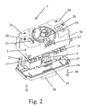
- Fig. 2
- die Lichtbedieneinheit wie in Fig. 1, jedoch ohne Betätigungsorgan sowie in erweiterter Explosionsdarstellung,
- Fig. 3
- die Lichtbedieneinheit wie in Fig. 2, wobei das Gehäuse entfernt ist,
- Fig. 4
- eine Explosionsdarstellung der Lichtbedieneinheit entsprechend Fig. 3,
- Fig. 5
- das Betätigungsorgan mit Halteteil als Einzelteil in perspektivischer Ansicht,
- Fig. 6
- das Betätigungsorgan mit Halterung aus Fig. 5 in Seitenansicht,
- Fig. 7
- eine Lichtbedieneinheit in einer weiteren Ausführung, ansonsten jedoch in einer Ansicht wie in Fig. 1,
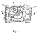
- Fig. 8
- ein Einzelteil des Gehäuses aus Fig. 7 in Draufsicht,
- Fig. 9
- einen Schnitt entlang der Linie 9-9 in Fig. 8,
- Fig. 10
- die Achse für das Betätigungsorgan als Einzelteil und
- Fig. 11
- schematisch das Zusammenwirken zwischen der Achse und den Schnapp- und/oder Rasthaken.
- Fig. 1
- a light control unit for a motor vehicle in perspective view and partial exploded view,
- Fig. 2
- the light control unit as in Fig. 1, but without actuator and in an expanded exploded view,
- Fig. 3
- the light control unit as in Fig. 2, with the housing removed,
- Fig. 4
- an exploded view of the light control unit according to FIG. 3,
- Fig. 5
- the actuator with holding part as an individual part in perspective view,
- Fig. 6
- the actuator with bracket of FIG. 5 in side view,
- Fig. 7
- a light control unit in a further embodiment, but otherwise in a view as in Fig. 1,
- Fig. 8
- an item of the housing of FIG. 7 in plan view,
- Fig. 9
- a section along the line 9-9 in Fig. 8,
- Fig. 10
- the axis for the actuator as a single part and
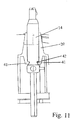
- Fig. 11
- schematically the interaction between the axis and the snap and / or snap hooks.
In Fig. 1 ist eine als Steuergerät ausgebildete Lichtbedieneinheit 1 für ein Kraftfahrzeug in teilweiser Explosionsdarstellung gezeigt. Die Lichtbedieneinheit 1 umfaßt einen elektrischen Schalter 2 zum Schalten der Beleuchtung des Kraftfahrzeugs. Weiter besitzt die Lichtbedieneinheit 1 ein Gehäuse 3, aus dem ein Betätigungsorgan 4 zur Bedienung des elektrischen Schalters 2 durch den Benutzer herausragt. Im Gehäuse 3 befindet sich weiter ein in Fig. 4 sichtbares Kontaktsystem 5, das zur Verhinderung von Verschmutzungen gekapselt ist. Das Kontaktsystem 5 ist mittels des Betätigungsorgans 4 schaltbar. Das Betätigungsorgan 4 ist derart augestaltet, daß durch Einwirkung einer einen Schwellwert überschreitenden Kraft auf das Betätigungsorgan 4, dieses wenigstens teilweise im Gehäuse 3 versenkbar ist. Als zweckmäßig für Kraftfahrzeuganwendungen hat es sich herausgestellt, wenn der Schwellwert für die Kraft ca. 300 bis 400 Newton beträgt.In Fig. 1 designed as a control unit
Bei dem elektrischen Schalter 2 handelt es sich um einen Drehrastschalter, bei dem das Betätigungsorgan 4 drehbar im Gehäuse 3 gelagert ist. Das in der Art eines Drehknopfes ausgebildete Betätigungsorgan 4 ist von einer Blende 33 umgeben. Das Kontaktsystem 5 wird somit durch eine manuelle Drehbewegung des Betätigungsorgans 4 gemäß Pfeil 6 vom Benutzer geschaltet. Hierfür weist das Betätigungsorgan 4 einen im Gehäuse 3 angeordneten Schaft 14 bzw. eine Achse 14 auf, wobei der Schaft 14 an einem in Fig. 3 sichtbaren Rotor 15 derart angreift, daß der Rotor 15 mittels des Betätigungsorgans 4 drehbar ist. Wie weiter aus Fig. 3 hervorgeht, ist der Rotor 15 seinerseits in einer im Gehäuse 3 befindlichen Halterung 17 drehbar gelagert und wirkt mittels eines federbelasteten Stößels 18 mit einer Rastkurve 19 in der Halterung 17 zur Festlegung der Rastpositionen zusammen. Der Rotor 15 betätigt wiederum das Kontaktsystem 5 mittels eines Ansatzes 16, der in eine in Fig. 4 sichtbare Aufnahme 36 am Kontaktsystem 5 eingreift.The
Wie man in Fig. 1 sieht, ist der Schaft 14 am Betätigungsorgan 4 in einem hülsenartigen Ansatz 20 an einem Halteteil 35 im Gehäuse 3 gelagert. Zweckmäßigerweise ist nun das Betätigungsorgan 4 in axialer Richtung entsprechend dem Pfeil 7 in Bezug auf die Drehbewegung, und damit in etwa senkrecht zu der Oberfläche 8 des Gehäuses 3, an der das Betätigungsorgan 4 herausragt, zur Versenkung in das Gehäuse 3 bewegbar. Hierzu ist der Schaft 14 gegen den Rotor 15 axial verschiebbar, indem der hülsenförmige Schaft 14 eine Welle 21 am Rotor 15 übergreift, wie anhand der beiden Fig. 1 und 3 zu erkennen ist. Die Welle 21 und der hülsenförmige Schaft 14 sind im übrigen gleichermaßen profiliert ausgestaltet, um trotz der axialen Verschiebbarkeit des Schaftes 14 ein Drehen des Rotors 15 mittels des Betätigungsorgans 4 zu gestatten. Ist das Betätigungsorgan 4 im Gehäuse 3 versenkt, so läßt sich dieses durch eine vom Benutzer aufgebrachte Zugkraft in Gegenrichtung zur Versenkung entsprechend dem Pfeil 7' wieder aus dem Gehäuse 3 herausbewegen. Die Bewegung in axialer Richtung gemäß Pfeil 7' erfolgt dann soweit bis das Betätigungsorgan 4 wieder in seine ursprüngliche, aus dem Gehäuse 3 herausragende Position gelangt, in der das Betätigungsorgan 4 dann gehalten ist.As can be seen in Fig. 1, the
Um das Betätigungsorgan 4 in der aus dem Gehäuse 3 herausragenden Position zu halten, ist gemäß dem in Fig. 1 gezeigten ersten Ausführungsbeispiel ein Federelement 9 mit einem Ende im Gehäuse 3 befestigt. Mit seinem anderen freien Ende wirkt das Federelement 9 mit dem Betätigungsorgan 4 zusammen. Dadurch ist zum einen, wie bereits erwähnt, das Betätigungsorgan 4 in der aus dem Gehäuse 3 herausragenden Position gehalten, wobei das Betätigungsorgan 4 gleichzeitig zum Schalten des Kontaktsystems 5 frei drehbar ist. Zum anderen gibt das Federelement 9 jedoch bei Überschreiten der Schwellkraft das Betätigungsorgan 4 frei, so daß dieses in das Gehäuse 3 eintauchen kann.In order to hold the
Wie man näher anhand der Fig. 5 sieht, ist das Federelement 9 in der Art einer in etwa U-förmigen Schenkelfeder ausgestaltet. Die Schenkelfeder 9 ist an der Basis 11 des U's an Rasthaken 12, die sich am Halteteil 35 befinden, im Gehäuse 3 verclipsend befestigt. Die beiden freien Schenkel 10, 10' des U's der Schenkelfeder 9 verlaufen in etwa senkrecht zur axialen Richtung 7, 7' und ragen durch eine Öffnung 22 in das Halteteil 35 hinein. Im Bereich der Öffnung 22 liegen die Schenkel 10, 10' am Halteteil 35 auf und greifen im Halteteil 35 in eine am Betätigungsorgan 4, und zwar am Schaft 14 befindliche sowie in Fig. 6 sichtbare Nut 13 unter Ausübung einer elastischen Klemmkraft ein. Aufgrund dieser Klemmkraft wird das Betätigungsorgan 4 in seiner aus dem Gehäuse 3 herausragenden Position gehalten. Der kompakten Anordnung halber im Gehäuse 3 können die Schenkel 10, 10' mit einer Abkröpfung 37 versehen sein, wie in Fig. 6 gezeigt ist.As can be seen in more detail with reference to FIG. 5, the
Bei Krafteinleitung auf das Betätigungsorgan 4 in axialer Richtung, die einen bestimmten Schwellwert überschreitet, spreizen sich die Schenkel 10, 10' auf, und das Betätigungsorgan 4 taucht dann in das Gehäuse 3 ein. Wie in Fig. 6 angedeutet ist, ist die am Schaft 14 umlaufende Nut 13 mit einer Schräge in der Art einer schiefen Ebene versehen. Durch Änderung des Winkel der schiefen Ebene läßt sich somit der Schwellwert für die Eintauchkraft wunschgemäß variieren. Genausogut läßt sich eine variable Eintauch- und Rückziehkraft für das Betätigungsorgan 4 durch eine veränderte Geometrie der Nut 13 und/oder Federkraft der Schenkel 10, 10' und/oder Materialwahl für das Federelement 9 realisieren. Hervorzuheben ist jedoch, daß die vom Benutzer fühlbare Haptik für die Drehung des Betätigungsorgans 4 durch das Federelement 9 an sich im wesentlichen unbeeinflußt bleibt. Beim Herausziehen des Betätigungsorgans 4 aus dem Gehäuse 3 springen dann die Schenkel 10, 10' bei Erreichen der ursprünglichen Position wieder in die Nut 13 zurück.When force is applied to the
Wie in Fig. 2 zu sehen ist, können im und/oder am Gehäuse 3 der Lichtbedieneinheit 1 noch weitere Schalter mit Kontaktsystemen 23 angeordnet sein, beispielsweise um die Parkleuchten am Kraftfahrzeug zu schalten. Die Betätigungsorgane 24 für die Kontaktsysteme 23 sind als Drucktasten ausgebildet. Ebenso können diese Betätigungsorgane in der Art von Wippen ausgebildet sein, was jedoch nicht weiter gezeigt ist. Weiterhin befinden sich im Gehäuse 3 noch in Fig. 4 sichtbare Potentiometer 25, beispielsweise für eine Leuchtweitenregelung des Kraftfahrzeugs und/oder eine Dimmfunktion der Lichtbedieneinheit 1. Die Potentiometer 25 werden mittels Rändelräder 26 als Betätigungsorgane durch den Benutzer bedient. Selbstverständlich können auch sonstige, nicht weiter gezeigte Bedienelemente in der Lichtbedieneinheit 1 angeordnet sein, so daß noch sonstige weitere Schaltfunktionen zusätzlich zum Drehschalten, das mittels des Betätigungsorgans 4 bewirkbar ist, sowie den genannten Schaltfunktionen durch den Benutzer betätigbar sind.As can be seen in FIG. 2, further switches with
Wie weiter in Fig. 2 gezeigt ist, besteht das Gehäuse 3 aus einem Oberteil 38 und einem Unterteil 39, die miteinander durch Schrauben 40 verbunden sind. Im Gehäuse 3 ist eine Leiterplatte 27 zur Aufnahme des wenigstens einen Kontaktsystems 5 angeordnet. Falls vorhanden, befinden sich zweckmäßigerweise auch die weiteren Kontaktsysteme 23 sowie die Potentiometer 25 und/oder die weiteren elektrischen/elektronischen Bauelemente auf der Leiterplatte 27. Soweit gewünscht ist auf der Leiterplatte 27 eine Elektronik, beispielsweise ein Mikroprozessor, zur Verarbeitung der Schaltsignale der Kontaktsysteme 5, 23 sowie der Potentiometer 25 und gegebenenfalls zur Erzeugung von Bussignalen befindlich. Am Gehäuse 3 ist ein mit der Leiterplatte 27 über Verbindungsstifte 34 in elektrischer Verbindung stehender elektrischer Anschluß 28 für ein Bussystem angeordnet. Selbstverständlich können die Schaltsignale der Kontaktsysteme 5, 23 sowie der Potentiometer 25 auch direkt über den Anschluß 28 zu einem Steuergerät für die Kraftfahrzeug-Beleuchtung weitergeleitet werden, so daß in diesem Fall auf eine entsprechende Elektronik zur Verarbeitung der Schaltsignale in der Lichtbedieneinheit 1 verzichtet werden kann. Schließlich befinden sich auf der Leiterplatte 27 noch in Fig. 4 sichtbare Leuchtdioden 29, 29' zur Beleuchtung von in Fig. 1 dargestellten Symbolen 30, Anzeigen 31 o. dgl. an den Betätigungsorganen 4, 24, 26 und/oder am Gehäuse 3 und/oder an der Blende 33, um dem Benutzer eine entsprechende Orientierung zu gestatten. Das von den Leuchtdioden 29 abgestrahlte Licht kann über Lichtleitelemente 32 zu den zugehörigen Symbolen 30 oder Anzeigen 31 geführt werden.As further shown in Fig. 2, the
Eine Lichtbedieneinheit 1 gemäß einem weiteren, zweiten Ausführungsbeispiel ist in perspektivischer Ansicht in Fig. 7 gezeigt. Bei dieser Lichtbedieneinheit 1 ist kein Federelement 9 verwendet, ansonsten ist diese jedoch im wesentlichen gleich wie diejenige des ersten Ausführungsbeispiels ausgestaltet, so daß auch hier zur Verdeutlichung noch die Fig. 2 bis 4 herangezogen werden können. Anstelle des Federelements 9 befinden sich bei dieser weiteren Ausführung im hülsenartigen Ansatz 20 des Gehäuses 3 Schnapp- und/oder Rasthaken 41, wie anhand der Fig. 8 oder 9 zu erkennen ist, um das Betätigungsorgan 4 in der aus dem Gehäuse 3 herausragenden Position zu halten.A
Die Schnapp- und/oder Rasthaken 41 greifen in eine in Fig. 10 sichtbare Nut 42 an der Achse 14 ein. Wie in Fig. 11 schematisch gezeigt ist, ist dadurch die im hülsenartigen Ansatz 20 geführte Achse 14 mittels der Schnapp- und/oder Rasthaken 41 in der Position, in der das Betätigungsorgan 4 aus dem Gehäuse 3 herausragt, festgehalten, wobei jedoch die freie Drehbarkeit der Achse 14 zum Schalten des Kontaktsystems 5 gewährleistet ist. Bei Überschreiten der Schwellkraft erfolgt dann eine Aufspreizung der Schnapp- und/oder Rasthaken 41, derart daß die Achse 14 zur Versenkung des Betätigungsorgans 4 im Gehäuse 3 freigegeben ist. Aufgrund der Elastizität der Schnapp- und/oder Rasthaken 41 schnappen diese dann beim Herausziehen des Betätigungsorgans 4 aus dem Gehäuse 3 wieder in die Nut 42 ein. Wie besonders deutlich in Fig. 10 gezeigt ist, ist die Nut 42 zum Zweck der Anpassung des Schwellwerts als einseitig schiefe Ebene ausgestaltet.The snap-in and / or snap-in
Das in Fig. 5 gezeigte Federelement 9 besteht zweckmäßigerweise aus Metall. Die in Fig. 9 sichtbaren Schnapp- und/oder Rasthaken 41 bestehen aus Kunststoff. Da das Gehäuse 3 ebenfalls aus Kunststoff besteht, können die Schnapp- und/oder Rasthaken 41 bei Herstellung des Oberteils 38 des Gehäuses 3 einstückig an den hülsenartigen Ansatz 20 angespritzt werden. Die Schnapp- und/oder Rasthaken 41 sind, wie anhand der Fig. 9 zu erkennen ist, derart im Inneren des hülsenförmigen Ansatzes 20 angeordnet, daß eine Bewegungsmöglichkeit in etwa quer zu axialen Richtung 7, 7' gegeben ist, um die Aufspreizbarkeit der Schnapp- und/oder Rasthaken 41 zu ermöglichen. An der Achse 14 befindet sich ein Anschlag 43, wie in Fig. 10 zu sehen ist, der zur Begrenzung der Bewegung der Achse 14 in axialer Richtung 7, 7' dient. Schließlich ist entsprechend der Fig. 8 der hülsenförmige Ansatz 20 mit im Gehäuse 3 befindlichen Versteifungsrippen 44 versehen.The
Die Erfindung ist nicht auf das beschriebene und dargestellte Ausführungsbeispiel beschränkt. Sie umfaßt vielmehr auch alle fachmännischen Weiterbildungen im Rahmen der durch die Patentansprüche definierten Erfindung. So kann die Erfindung nicht nur an elektrischen Schaltern für Kraftfahrzeuge eingesetzt werden, sondern auch an Schaltern mit einem versenkbaren Betätigungsorgan für Haushaltsgeräte, Werkzeugmaschinen, Elektrowerkzeuge o. dgl. Verwendung finden.The invention is not limited to the described and illustrated embodiment. Rather, it also encompasses all expert developments within the scope of the invention defined by the claims. Thus, the invention can not only be used on electrical switches for motor vehicles, but also on switches with a retractable actuator for household appliances, machine tools, power tools o. The like. Use find.
- 1:1:
- LichtbedieneinheitLight control unit
- 2:2:
- elektrischer Schalterelectrical switch
- 3:3:
- Gehäusecasing
- 4:4:
- Betätigungsorganactuator
- 5:5:
- KontaktsystemContact system
- 6:6:
- Pfeil für DrehbewegungArrow for rotary motion
- 7:7:
- Pfeil für axiale RichtungArrow for axial direction
- 7':7 ':
- Pfeil für GegenrichtungArrow for opposite direction
- 8:8th:
- Oberfläche (von Gehäuse)Surface (of housing)
- 9:9:
- Federelement / (U-förmige) SchenkelfederSpring element / (U-shaped) leg spring
- 10,10':10,10 ':
- Schenkel (von Federelement)Leg (of spring element)
- 11:11:
- Basis (von Federelement)Base (of spring element)
- 12:12:
- Rasthaken (für Befestigung von Federelement)Latching hook (for fastening of spring element)
- 13:13:
- Nutgroove
- 14:14:
- Schaft / Achse (an Betätigungsorgan)Shaft / axle (to actuator)
- 15:15:
- Rotorrotor
- 16:16:
- Ansatz (am Rotor)Approach (on the rotor)
- 17:17:
- Halterung (für den Rotor)Bracket (for the rotor)
- 18:18:
- Stößel (am Rotor)Ram (on the rotor)
- 19:19:
- Rastkurvelocking curve
- 20:20:
- hülsenartiger Ansatzsleeve-like approach
- 21:21:
- Wellewave
- 22:22:
- Öffnung (in Halteteil)Opening (in holding part)
- 23:23:
- Kontaktsystem (von weiterem Schalter)Contact system (from further switch)
- 24:24:
- Betätigungsorgan (für weiteren Schalter)Actuator (for another switch)
- 25:25:
- Potentiometerpotentiometer
- 26:26:
- Betätigungsorgan / Rändelrad (von Potentiometer)Actuator / knurl wheel (from potentiometer)
- 27:27:
- Leiterplattecircuit board
- 28:28:
- elektrischer Anschlußelectrical connection
- 29,29':29.29 ':
- Leuchtdiodeled
- 30:30:
- Symbolsymbol
- 31:31:
- Anzeigedisplay
- 32:32:
- Lichtleitelementlight guide
- 33:33:
- Blendecover
- 34:34:
- Verbindungsstiftconnecting pin
- 35:35:
- Halteteil (für hülsenartigen Ansatz)Holding part (for sleeve-like approach)
- 36:36:
- Aufnahme (am Kontaktsystem)Recording (on the contact system)
- 37:37:
- Abkröpfung (an Schenkel)Bend (on thigh)
- 38:38:
- Oberteil (von Gehäuse)Upper part (of housing)
- 39:39:
- Unterteil (von Gehäuse)Lower part (of housing)
- 40:40:
- Schraubescrew
- 41:41:
- Schnapp- und/oder RasthakenSnap-in and / or snap-in hooks
- 42:42:
- Nut (in der Achse)Groove (in the axis)
- 43:43:
- Anschlagattack
- 44:44:
- Versteifungsrippestiffening rib
Claims (11)
- Electric switch, in particular for a motor vehicle, such as for a light-operating unit (1) in a motor vehicle, with a housing (3), with an actuating member (4) projecting out of the housing (3), and with a contact system (5) located in the housing (3) that can be controlled by means of the actuating member (4), whereby the actuating member (4) can be recessed by means of a force exceeding a threshold value, and whereby the recessed actuating member (4) can be moved out of the recess by a pulling force in the opposite direction (7'), such that the actuating member (4) after being recessed and then moved out is held again in its original projecting position, characterised in that the actuating member (4) can be recessed at least partly in the housing (3), and in that the actuating member (4) cooperates with a spring element (9) in the housing (3) or with snap and/or detent hooks (41), so that on the one hand the actuating member (4) is held in the position projecting out of the housing (3), in particular in a freely rotatable manner, and on the other hand when the threshold force is exceeded the actuating member (4) is released for recessing.
- Electric switch according to claim 1, characterised in that the actuating member (4) is mounted rotatably in the housing (3), preferably by means of a shaft (14), an axle (14) or the like, in particular as a kind of rotary locking switch, such that the contact system (5) is controlled by a rotary movement of the actuating member (4), and in that preferably the actuating member (4) can be moved in axial direction (7) in relation to the rotary movement (6), in particular perpendicular to the surface (8) of the housing (3), from which the actuating member (4) projects, for recessing into the housing (3).
- Electric switch according to claim 1 or 2, characterised in that a spring element (9) is secured at one end in the housing (3) and cooperates at the other free end with the actuating member (4).
- Electric switch according to claim 1, 2 or 3, characterised in that the spring element (9) is designed as a kind of U-shaped leg spring, in that preferably the leg spring (9) is secured to the base (11) of the U in the housing (3), and in that also preferably the two free, possibly crimped legs (10, 10') of the U engage in a groove (13) located on the actuating member (4) under elastic clamping force.
- Electric switch according to one of claims 1 to 4, characterised in that the actuating member (4) comprises a shaft (14), axle (14) or the like arranged in the housing (3), in that preferably the shaft (14), axle (14) or the like, is attached to a rotor (15) operating the contact system (5), such that on the one hand the rotor (15) can be rotated by means of the actuating member (4) and on the other hand the shaft (14), axle (14) or the like can be displaced axially relative to the rotor (15), and in that also preferably the groove (13) for mounting the legs (10, 10') of the leg spring (9) is located on the shaft (14), axle (14) or the like.
- Electric switch according to one of claims 1 to 5, characterised in that the rotor (15) is rotatably mounted in a holder (17) located in a housing (3), in that preferably the rotor (15) cooperates by means of a spring-loaded ram (18) with a detent curve (19) for securing the detent positions, in that also preferably the shaft (14), axle (14) or the like is mounted in a sleeve-type shoulder (20) on a holding part (35) in the housing (3), and in that also preferably the legs (10,10') of the leg spring (9) project through an opening (22) into the holding part (35) for engagement in the groove (13) on the shaft (14).
- Electric switch according to one of claims 1 to 6, characterised in that in and/or on the housing (3) actuating members (24, 26), in particular in the form of pushbuttons, rockers, knurled wheels or the like, are arranged for contact systems (23) of additional switches for potentiometers (25) or the like, so that in addition to rotational switching actuatable by means of the actuating member (4) further switching functions can be actuated.
- Electric switch according to one of claims 1 to 7, characterised in that in the housing (3) a circuit board (27) is arranged for mounting the at least one contact system (5, 23) of the potentiometer (25) or the like, in that preferably on the circuit board (27) electronics are located for processing the switching signals and if necessary for generating bus signals, in that also preferably on the housing (3) there is a connection (28) in electrical contact with the circuit board (27), in particular for a bus system, and in that also preferably on the circuit board (27) light-emitting diodes (29, 29') are arranged to illuminate, in particular via optical-fibre elements (32), symbols (30), displays (31) or the like on the actuating members (4, 24, 26) and/or on the housing (3).
- Electric switch according to one of claims 1 to 8, characterised in that the snap and/or detent hooks (41) are located in a sleeve-shape shoulder (20) in the housing (3), in that preferably the axle (14) guided in particular in the sleeve-shaped shoulder (20) is secured by means of the snap and/or detent hooks (41) in the position in which the actuating member (4) projects out of the housing (3), in particular so as to be freely rotatable, in that preferably the snap and/or detent hooks (41) engage in a groove (42) on the axle (14) and in that also preferably on exceeding the threshold force the snap and/or detent hooks (41) spread apart such that the axle (14) is released for recessing the actuating member (4) in the housing (3).
- Electric switch according to one of claims 1 to 9, characterised in that the spring element (9) is made of metal.
- Electric switch according to one of claims 1 to 9, characterised in that the snap and/or detent hooks (41) are made of plastic and are injected in particular in one piece onto the sleeve-shaped shoulder (20), in that preferably the snap and/or detent hooks (41) are arranged on the inside of the sleeve-shaped shoulder (20) such that movement is possible perpendicular to the axial direction (7, 7') in relation to their spreadability, in that also preferably on the axle (14) a stop (43) is positioned for limiting the movement of the axle (14) in axial direction (7,7'), and in that also preferably the sleeve-shaped shoulder (20) is provided with reinforcing ribs (44) located in the housing (3).
Applications Claiming Priority (4)
| Application Number | Priority Date | Filing Date | Title |
|---|---|---|---|
| DE10304036 | 2003-02-01 | ||
| DE10304036 | 2003-02-01 | ||
| DE10341017 | 2003-09-03 | ||
| DE10341017 | 2003-09-03 |
Publications (3)
| Publication Number | Publication Date |
|---|---|
| EP1443533A2 EP1443533A2 (en) | 2004-08-04 |
| EP1443533A3 EP1443533A3 (en) | 2005-09-21 |
| EP1443533B1 true EP1443533B1 (en) | 2007-02-28 |
Family
ID=32657778
Family Applications (1)
| Application Number | Title | Priority Date | Filing Date |
|---|---|---|---|
| EP04001931A Expired - Lifetime EP1443533B1 (en) | 2003-02-01 | 2004-01-29 | Electrical switches |
Country Status (3)
| Country | Link |
|---|---|
| EP (1) | EP1443533B1 (en) |
| AT (1) | ATE355600T1 (en) |
| DE (2) | DE102004004471A1 (en) |
Families Citing this family (6)
| Publication number | Priority date | Publication date | Assignee | Title |
|---|---|---|---|---|
| GB0418358D0 (en) * | 2004-08-18 | 2004-09-22 | Ford Global Tech Llc | Selector mechanism for a motor vehicle transmission |
| DE102004054178B4 (en) * | 2004-11-10 | 2010-09-02 | Preh Gmbh | Control element for control units in motor vehicles |
| FR2879843B1 (en) * | 2004-12-21 | 2008-08-22 | Sc2N Sa | SWITCHING CONTROL DEVICE FOR MOTOR VEHICLE |
| DE102013208640B4 (en) | 2013-05-10 | 2019-03-28 | GSI Glastechnologie GmbH | Operating device with a base plate made of a non-magnetic material and a touch-sensitive sensor |
| DE102014005082A1 (en) | 2014-04-05 | 2015-10-08 | Audi Ag | Control device for controlling at least one outdoor lighting device |
| US9881752B2 (en) | 2015-12-02 | 2018-01-30 | Kabushiki Kaisha Tokai Rika Denki Seisakusho | Rotary-type switch |
Family Cites Families (3)
| Publication number | Priority date | Publication date | Assignee | Title |
|---|---|---|---|---|
| US4051916A (en) * | 1975-12-22 | 1977-10-04 | Nissan Motor Company, Limited | Apparatus for mounting instrument to instrument panel in motor vehicle |
| DE4203427C2 (en) * | 1992-02-06 | 1999-07-08 | Haschkamp Ernestine | Cam rotary switch |
| DE20120667U1 (en) * | 2001-12-20 | 2002-12-12 | Siemens Ag | Deformable push button |
-
2004
- 2004-01-28 DE DE102004004471A patent/DE102004004471A1/en not_active Withdrawn
- 2004-01-29 DE DE502004002996T patent/DE502004002996D1/en not_active Expired - Lifetime
- 2004-01-29 AT AT04001931T patent/ATE355600T1/en not_active IP Right Cessation
- 2004-01-29 EP EP04001931A patent/EP1443533B1/en not_active Expired - Lifetime
Also Published As
| Publication number | Publication date |
|---|---|
| EP1443533A3 (en) | 2005-09-21 |
| DE102004004471A1 (en) | 2004-08-05 |
| EP1443533A2 (en) | 2004-08-04 |
| ATE355600T1 (en) | 2006-03-15 |
| DE502004002996D1 (en) | 2007-04-12 |
Similar Documents
| Publication | Publication Date | Title |
|---|---|---|
| EP0876940B1 (en) | Multifunction push-button switch | |
| DE19844336C1 (en) | Electric switch for adjustment of automobile passenger seat or rear view mirror | |
| DE19723482C1 (en) | Electric rotary/slider switch e.g. for motor vehicle lighting and windscreen wipers | |
| EP1129886A2 (en) | Electrical switching element for motor vehicle with separate symbol zone | |
| EP1443533B1 (en) | Electrical switches | |
| DE10040713B4 (en) | Electric switch | |
| EP0587056B1 (en) | Rocker keyswitch | |
| DE10309823B4 (en) | Washing machine with a control panel | |
| EP0902448A2 (en) | Electrical installation device in particular feeler, actuator or switch | |
| EP0887819A2 (en) | Electric push-button switch | |
| DE19514539C2 (en) | Multi-function switch, in particular mirror adjustment switch for a motor vehicle | |
| DE3727495C1 (en) | Latching device for electrical switches | |
| EP0897584B1 (en) | Rocker switch, particularly for motor vehicle window lift | |
| EP1240655B1 (en) | Electric switch | |
| DE4410771B4 (en) | Switch, in particular in the dashboard of a motor vehicle installable switch, and method for producing a switch | |
| DE10259605B3 (en) | Electrical toggle switch has part consisting of base body associated with movable contact elements and control body associated with different control curves movable to defined positions on base body | |
| DE10254992B4 (en) | Electric switch | |
| DE19963144B4 (en) | Self-adjusting push-button switch | |
| DE10202955B4 (en) | Interior light for a motor vehicle | |
| DE19927187A1 (en) | Storage container for vehicle with illumination device has actuation element for lighting switch contacts formed by housing container or closure part or by connected protrusion | |
| DE3921698C1 (en) | Control or switching appts. - has free-standing end region for multifunctional switching and tubular intermediate section accepting electrical leads | |
| DE19946601C1 (en) | Switching device, in particular for a gas boiler | |
| DE4334054A1 (en) | Electrical switch | |
| DE3546625C2 (en) | Electrical rotary switch having illumination | |
| DE10130251C1 (en) | Push-button switch housing has guide for switch push-button forming pin contact chamber with base plate for electronic components |
Legal Events
| Date | Code | Title | Description |
|---|---|---|---|
| PUAI | Public reference made under article 153(3) epc to a published international application that has entered the european phase |
Free format text: ORIGINAL CODE: 0009012 |
|
| AK | Designated contracting states |
Kind code of ref document: A2 Designated state(s): AT BE BG CH CY CZ DE DK EE ES FI FR GB GR HU IE IT LI LU MC NL PT RO SE SI SK TR |
|
| AX | Request for extension of the european patent |
Extension state: AL LT LV MK |
|
| PUAL | Search report despatched |
Free format text: ORIGINAL CODE: 0009013 |
|
| AK | Designated contracting states |
Kind code of ref document: A3 Designated state(s): AT BE BG CH CY CZ DE DK EE ES FI FR GB GR HU IE IT LI LU MC NL PT RO SE SI SK TR |
|
| AX | Request for extension of the european patent |
Extension state: AL LT LV MK |
|
| RIC1 | Information provided on ipc code assigned before grant |
Ipc: 7H 01R 3/08 B Ipc: 7H 01H 3/00 A |
|
| 17P | Request for examination filed |
Effective date: 20051129 |
|
| AKX | Designation fees paid |
Designated state(s): AT BE BG CH CY CZ DE DK EE ES FI FR GB GR HU IE IT LI LU MC NL PT RO SE SI SK TR |
|
| GRAP | Despatch of communication of intention to grant a patent |
Free format text: ORIGINAL CODE: EPIDOSNIGR1 |
|
| GRAS | Grant fee paid |
Free format text: ORIGINAL CODE: EPIDOSNIGR3 |
|
| GRAA | (expected) grant |
Free format text: ORIGINAL CODE: 0009210 |
|
| AK | Designated contracting states |
Kind code of ref document: B1 Designated state(s): AT BE BG CH CY CZ DE DK EE ES FI FR GB GR HU IE IT LI LU MC NL PT RO SE SI SK TR |
|
| PG25 | Lapsed in a contracting state [announced via postgrant information from national office to epo] |
Ref country code: NL Free format text: LAPSE BECAUSE OF FAILURE TO SUBMIT A TRANSLATION OF THE DESCRIPTION OR TO PAY THE FEE WITHIN THE PRESCRIBED TIME-LIMIT Effective date: 20070228 Ref country code: DK Free format text: LAPSE BECAUSE OF FAILURE TO SUBMIT A TRANSLATION OF THE DESCRIPTION OR TO PAY THE FEE WITHIN THE PRESCRIBED TIME-LIMIT Effective date: 20070228 Ref country code: SI Free format text: LAPSE BECAUSE OF FAILURE TO SUBMIT A TRANSLATION OF THE DESCRIPTION OR TO PAY THE FEE WITHIN THE PRESCRIBED TIME-LIMIT Effective date: 20070228 Ref country code: FI Free format text: LAPSE BECAUSE OF FAILURE TO SUBMIT A TRANSLATION OF THE DESCRIPTION OR TO PAY THE FEE WITHIN THE PRESCRIBED TIME-LIMIT Effective date: 20070228 Ref country code: IE Free format text: LAPSE BECAUSE OF FAILURE TO SUBMIT A TRANSLATION OF THE DESCRIPTION OR TO PAY THE FEE WITHIN THE PRESCRIBED TIME-LIMIT Effective date: 20070228 |
|
| REG | Reference to a national code |
Ref country code: GB Ref legal event code: FG4D Free format text: NOT ENGLISH |
|
| REG | Reference to a national code |
Ref country code: CH Ref legal event code: EP |
|
| REF | Corresponds to: |
Ref document number: 502004002996 Country of ref document: DE Date of ref document: 20070412 Kind code of ref document: P |
|
| REG | Reference to a national code |
Ref country code: IE Ref legal event code: FG4D Free format text: LANGUAGE OF EP DOCUMENT: GERMAN |
|
| PG25 | Lapsed in a contracting state [announced via postgrant information from national office to epo] |
Ref country code: BG Free format text: LAPSE BECAUSE OF EXPIRATION OF PROTECTION Effective date: 20070529 |
|
| PG25 | Lapsed in a contracting state [announced via postgrant information from national office to epo] |
Ref country code: SE Free format text: LAPSE BECAUSE OF FAILURE TO SUBMIT A TRANSLATION OF THE DESCRIPTION OR TO PAY THE FEE WITHIN THE PRESCRIBED TIME-LIMIT Effective date: 20070531 |
|
| PG25 | Lapsed in a contracting state [announced via postgrant information from national office to epo] |
Ref country code: ES Free format text: LAPSE BECAUSE OF FAILURE TO SUBMIT A TRANSLATION OF THE DESCRIPTION OR TO PAY THE FEE WITHIN THE PRESCRIBED TIME-LIMIT Effective date: 20070608 |
|
| PG25 | Lapsed in a contracting state [announced via postgrant information from national office to epo] |
Ref country code: PT Free format text: LAPSE BECAUSE OF FAILURE TO SUBMIT A TRANSLATION OF THE DESCRIPTION OR TO PAY THE FEE WITHIN THE PRESCRIBED TIME-LIMIT Effective date: 20070730 |
|
| NLV1 | Nl: lapsed or annulled due to failure to fulfill the requirements of art. 29p and 29m of the patents act | ||
| GBV | Gb: ep patent (uk) treated as always having been void in accordance with gb section 77(7)/1977 [no translation filed] |
Effective date: 20070228 |
|
| REG | Reference to a national code |
Ref country code: IE Ref legal event code: FD4D |
|
| EN | Fr: translation not filed | ||
| PG25 | Lapsed in a contracting state [announced via postgrant information from national office to epo] |
Ref country code: SK Free format text: LAPSE BECAUSE OF FAILURE TO SUBMIT A TRANSLATION OF THE DESCRIPTION OR TO PAY THE FEE WITHIN THE PRESCRIBED TIME-LIMIT Effective date: 20070228 Ref country code: GB Free format text: LAPSE BECAUSE OF FAILURE TO SUBMIT A TRANSLATION OF THE DESCRIPTION OR TO PAY THE FEE WITHIN THE PRESCRIBED TIME-LIMIT Effective date: 20070228 |
|
| PG25 | Lapsed in a contracting state [announced via postgrant information from national office to epo] |
Ref country code: CZ Free format text: LAPSE BECAUSE OF FAILURE TO SUBMIT A TRANSLATION OF THE DESCRIPTION OR TO PAY THE FEE WITHIN THE PRESCRIBED TIME-LIMIT Effective date: 20070228 Ref country code: RO Free format text: LAPSE BECAUSE OF FAILURE TO SUBMIT A TRANSLATION OF THE DESCRIPTION OR TO PAY THE FEE WITHIN THE PRESCRIBED TIME-LIMIT Effective date: 20070228 |
|
| PLBE | No opposition filed within time limit |
Free format text: ORIGINAL CODE: 0009261 |
|
| STAA | Information on the status of an ep patent application or granted ep patent |
Free format text: STATUS: NO OPPOSITION FILED WITHIN TIME LIMIT |
|
| 26N | No opposition filed |
Effective date: 20071129 |
|
| PG25 | Lapsed in a contracting state [announced via postgrant information from national office to epo] |
Ref country code: IT Free format text: LAPSE BECAUSE OF FAILURE TO SUBMIT A TRANSLATION OF THE DESCRIPTION OR TO PAY THE FEE WITHIN THE PRESCRIBED TIME-LIMIT Effective date: 20070228 Ref country code: FR Free format text: LAPSE BECAUSE OF FAILURE TO SUBMIT A TRANSLATION OF THE DESCRIPTION OR TO PAY THE FEE WITHIN THE PRESCRIBED TIME-LIMIT Effective date: 20071019 Ref country code: GR Free format text: LAPSE BECAUSE OF FAILURE TO SUBMIT A TRANSLATION OF THE DESCRIPTION OR TO PAY THE FEE WITHIN THE PRESCRIBED TIME-LIMIT Effective date: 20070529 |
|
| BERE | Be: lapsed |
Owner name: MARQUARDT G.M.B.H. Effective date: 20080131 |
|
| PG25 | Lapsed in a contracting state [announced via postgrant information from national office to epo] |
Ref country code: MC Free format text: LAPSE BECAUSE OF NON-PAYMENT OF DUE FEES Effective date: 20080131 |
|
| REG | Reference to a national code |
Ref country code: CH Ref legal event code: PL |
|
| PG25 | Lapsed in a contracting state [announced via postgrant information from national office to epo] |
Ref country code: CH Free format text: LAPSE BECAUSE OF NON-PAYMENT OF DUE FEES Effective date: 20080131 Ref country code: LI Free format text: LAPSE BECAUSE OF NON-PAYMENT OF DUE FEES Effective date: 20080131 |
|
| PG25 | Lapsed in a contracting state [announced via postgrant information from national office to epo] |
Ref country code: FR Free format text: LAPSE BECAUSE OF FAILURE TO SUBMIT A TRANSLATION OF THE DESCRIPTION OR TO PAY THE FEE WITHIN THE PRESCRIBED TIME-LIMIT Effective date: 20070228 |
|
| PG25 | Lapsed in a contracting state [announced via postgrant information from national office to epo] |
Ref country code: EE Free format text: LAPSE BECAUSE OF FAILURE TO SUBMIT A TRANSLATION OF THE DESCRIPTION OR TO PAY THE FEE WITHIN THE PRESCRIBED TIME-LIMIT Effective date: 20070228 |
|
| PG25 | Lapsed in a contracting state [announced via postgrant information from national office to epo] |
Ref country code: BE Free format text: LAPSE BECAUSE OF NON-PAYMENT OF DUE FEES Effective date: 20080131 |
|
| PG25 | Lapsed in a contracting state [announced via postgrant information from national office to epo] |
Ref country code: AT Free format text: LAPSE BECAUSE OF NON-PAYMENT OF DUE FEES Effective date: 20080129 |
|
| PG25 | Lapsed in a contracting state [announced via postgrant information from national office to epo] |
Ref country code: CY Free format text: LAPSE BECAUSE OF FAILURE TO SUBMIT A TRANSLATION OF THE DESCRIPTION OR TO PAY THE FEE WITHIN THE PRESCRIBED TIME-LIMIT Effective date: 20070228 |
|
| PG25 | Lapsed in a contracting state [announced via postgrant information from national office to epo] |
Ref country code: LU Free format text: LAPSE BECAUSE OF NON-PAYMENT OF DUE FEES Effective date: 20080129 Ref country code: HU Free format text: LAPSE BECAUSE OF FAILURE TO SUBMIT A TRANSLATION OF THE DESCRIPTION OR TO PAY THE FEE WITHIN THE PRESCRIBED TIME-LIMIT Effective date: 20070901 |
|
| PG25 | Lapsed in a contracting state [announced via postgrant information from national office to epo] |
Ref country code: TR Free format text: LAPSE BECAUSE OF FAILURE TO SUBMIT A TRANSLATION OF THE DESCRIPTION OR TO PAY THE FEE WITHIN THE PRESCRIBED TIME-LIMIT Effective date: 20070228 |
|
| REG | Reference to a national code |
Ref country code: DE Ref legal event code: R082 Ref document number: 502004002996 Country of ref document: DE Representative=s name: PATENTANWAELTE STAEGER & SPERLING PARTNERSCHAF, DE Ref country code: DE Ref legal event code: R082 Ref document number: 502004002996 Country of ref document: DE Ref country code: DE Ref legal event code: R082 Ref document number: 502004002996 Country of ref document: DE Representative=s name: JOSTARNDT PATENTANWALTS-AG, DE |
|
| REG | Reference to a national code |
Ref legal event code: R082 Ref document number: 502004002996 Representative=s name: PATENTANWAELTE STAEGER & SPERLING PARTNERSCHAF, DE Ref country code: DE Country of ref document: DE |
|
| REG | Reference to a national code |
Ref country code: DE Ref legal event code: R082 Ref document number: 502004002996 Country of ref document: DE Representative=s name: PATENTANWAELTE STAEGER & SPERLING PARTNERSCHAF, DE |
|
| PGFP | Annual fee paid to national office [announced via postgrant information from national office to epo] |
Ref country code: DE Payment date: 20230119 Year of fee payment: 20 |
|
| P01 | Opt-out of the competence of the unified patent court (upc) registered |
Effective date: 20230522 |
|
| REG | Reference to a national code |
Ref country code: DE Ref legal event code: R071 Ref document number: 502004002996 Country of ref document: DE |