The artificial swamp that is used to dispose of sewage
Technical field
The utility model relates to technical field of sewage treatment, especially refers to a kind of artificial swamp that is used to dispose of sewage.
Background technology
Along with industrial expansion, the water pollution condition is serious all the more, and simultaneously, the contradiction between shortage of fresh water and living standards of the people improve is increasingly sharpened, and the task of water environment protection is also more and more arduous.In recent years, Research of Environmental Sciences is developing rapidly, trying to explore water environment pollution whole world effect problem, the method that various water treatments are polluted emerges in an endless stream, wherein ecological wastewater processing technology---artificial swamp technology, because its cost is economized, effluent quality is good, and is simple to operate, easy to maintenance, build, safeguard and working cost low (only be traditional B-grade sewage treatment plant 1/10~1/2), the ammonia nitrogen removal frank height, the while can make sewage disposal and environmental ecology construction combination, when disposing of sewage, increase greenery area, beautify ecotope, create characteristics such as urban ecology view, progressively accepted by more and more countries, and widespread use.
Artificial swamp be artificial build, the wet land system of controllable and through engineering approaches, its design and construction are by the physics in the wetland natural ecosystems, chemistry and biological three being acted synergistically, reaching the purifying treatment purpose to sewage.Artificial swamp generally by the pond body, fill out artificial substratum, water distribution system, water gathering system, the catchment area that is located at Chi Tizhong and the plant that is grown on the artificial substratum formed, it is the matrix-plant-microbial ecosystem of a uniqueness, during concrete enforcement, generally be on the depression that the certain long-width ratio and the bottom surface gradient are arranged, to build artificial swamp, artificial substratum adopts soil, filler (as gravel etc.) or its mixture mostly, and it is many that plant is then adopted waterplant such as reed, cattail, Canna generalis Bailey, wild rice stem.When sewage flowed into artificial swamp through water distribution system, sewage just flowed in the slit of matrix, the filtration of pollution substance process matrix wherein, absorption, ion-exchange, the absorption conversion of plant and the decomposition of microorganism, thus water quality is purified.
At present, many technology have been disclosed about artificial swamp, as application number is that the Chinese invention patent " high-density waterplant ditch Sewage treatment systems " of 03116101.4 (publication number is CN1533990A) discloses so a kind of artificial swamp, its sewage is among water distribution system flows into a plurality of irrigation canals and ditches that aquatic plants growth arranged, and water gathering system, the sewage of collection and treatment are installed at the irrigation canals and ditches of afterbody.But when practical application, this artificial swamp, the design of the selection of artificial substratum, water distribution system and water gathering system and water distribution system and water gathering system are provided with not enough science in matrix, the decontamination effect improving that occurs short stream of sewage and dead band easily and cause such as can not give full play at problem, therefore, some artificial wet land systems that improve purification efficiencies are invented, and are that the Chinese invention patent " a kind of strengthened artificial wet land sewage water treatment method and system " of ZL03150053.6 (notification number is CN1190371C) has just disclosed a kind of artificial swamp scheme as the patent No..It includes rectangular pond body, fill out the artificial substratum that is located at Chi Tizhong, water distribution system, water gathering system and the plant that is grown on the artificial substratum, water distribution system is water distributor and water distributing area, be arranged on the front end and 1/3rd places of pond body, and water gathering system is header and catchment area, be arranged on the afterbody of pond body, artificial substratum is a slag, red soil, the compounded mix that soil ulmin is formulated, this artificial swamp makes sewage enter into water distributing area by the water distributor at pond body front end and 1/3rd places, among sewage behind the water distributing area water distribution enters artificial substratum, sewage through purifying, is discharged the pond body through catchment area and header again in artificial substratum.But the water distribution system of this artificial swamp and water gathering system, its water distributing area and catchment area are vertically to be provided with in the body of pond, and become in the body of pond an independent subregion that is provided with, like this, sewage is that the facade from artificial substratum enters, and non-horizontal surface, opposite side is few in that distribution one side of artificial substratum is many certainly will to cause sewage, be the sewage skewness, this has just directly reduced the utilization ratio of artificial substratum, and the decontamination effect improving of sewage is also not ideal enough; Simultaneously, the sewage of this artificial swamp is not to be undercurrent among artificial substratum, often spills into the surface of artificial substratum, forms the surface current wetland, in the practice process, grows mosquito summer easily, produces foul smell, and then freeze easily on the wetland surface winter.
On the other hand, have a lot of impurity, mud in the sewage, flow through in the water distribution system pipeline and when being distributed in the middle of the artificial substratum, in pipeline, leave over these impurity, mud easily, will cause pipe blocking, thus influence use, generally need artificial extraction pipeline and separately it washed, clear up, cumbersome, and increased maintenance workload.Present existing artificial swamp, the piping design in its water distribution system also reckons without the washing function that self has.
Summary of the invention
First technical problem to be solved in the utility model is to provide a kind of artificial swamp that is used to dispose of sewage at above-mentioned prior art present situation, its sewage is evenly distributed in artificial substratum, thereby improve the utilization ratio and the wastewater purifying efficiency of artificial substratum, simultaneously, sewage only flows in artificial substratum, and can not form the surface current wetland, easily produce drawbacks such as mosquito, foul smell in the prior art thereby overcome.
Second technical problem to be solved in the utility model provides a kind of water distribution system and has the artificial swamp that is used to dispose of sewage that washing function prevents its line clogging then.
The utility model solves the technical scheme that above-mentioned first technical problem adopted: the artificial swamp that this is used to dispose of sewage, include the pond body, fill out artificial substratum, water distribution system, the water gathering system that is located at Chi Tizhong and be grown in plant on the artificial substratum, it is characterized in that:
About being isolated into by a watertight insulation, described pond body is respectively two subregions of one-level cloth pool and secondary catchment area, and leave the gap between this watertight insulation and the pond body bottom, two subregions bottom is interconnected, described artificial substratum then fill out respectively be located in this one-level cloth pool and the secondary catchment area in;
Described water distribution system is the one-level water distribution pipe network that is arranged on the artificial substratum upper strata in the one-level cloth pool, this one-level water distribution pipe network includes a water-in, coupled logical water distribution and is responsible for, is connected this water distribution and be responsible for and go up and its vertically disposed cloth water branch relatively, and, all have the water distribution aperture on the described water distribution person in charge, the cloth water branch;
And described water gathering system is the secondary that is distributed in the artificial substratum upper strata in the secondary catchment area pipe network that catchments, this secondary pipe network that catchments includes a water outlet and a plurality of branch that catchments that is connected with this water outlet, have the aperture that catchments in this branch that catchments, and the catchment height of pipe network of this secondary is lower than the height of one-level water distribution pipe network.
For further solving second above-mentioned technical problem, make the one-level water distributor netting gear in the artificial swamp that washing function be arranged, described one-level water distribution pipe network can also include the washpipe that an end has sewage draining exit, this washpipe is connected with described water distribution branches end and vertical setting of relative cloth water branch, and, also have the water distribution aperture on this washpipe.During the artificial swamp works better, this sewage draining exit is closed; When one-level water distribution pipe network was washed, current entered from the water-in of one-level water distribution pipe network, and the positive flushing water distribution person in charge, cloth water branch and washpipe itself then flow to extraneous from sewage draining exit; Simultaneously, this washpipe that has a water distribution aperture when the artificial swamp works better, is born the water distribution task equally, and when water distribution, sewage can vertically and directly flow in the middle of the artificial substratum by the water distribution aperture from washpipe.
Described artificial substratum can adopt existing various scheme, but for guaranteeing current unimpeded in artificial substratum, described one-level cloth is filled out the artificial substratum of establishing in the pool, can be pebble bed and coarse sands layer successively from bottom to up, and fill out the artificial substratum of establishing in the described secondary catchment area, can be pebble bed, melon seeds lamella and coarse sands layer successively from bottom to up.
For avoiding in the actual operation process, obscure between the layer of artificial substratum and the layer, fill out in the described one-level cloth pool between the pebble bed established and the coarse sands layer and can be provided with filtering layer, fill out in the described secondary catchment area between the melon seeds lamella established and the coarse sands layer and also can be provided with filtering layer, this filtering layer can simply adopt nylon net cloth, reaches the effect of separation.
Be to guarantee the decontamination effect improving of sewage, the area of described one-level cloth pool and secondary catchment area is assigned as good with 60%: 40% of the total area.
Be the surface-area of expansion artificial swamp and the ratio of the degree of depth, improve the utilization ratio of artificial substratum, the advantage of outstanding undercurrent, described pond body total depth is arranged between 1.0m~1.5m to good, so also saved land used, and the growth as long as enough root systems of plant distribute of described coarse sands layer, the thickness of general described coarse sands layer is being good between 0.1m~0.3m.
Be to improve the utilization ratio of artificial substratum, described one-level water distribution pipe network be laid on from artificial substratum surface 0.1m~0.3m be good apart from part, it is good from artificial substratum surface 0.2m~0.4m apart from part to be laid on then that described secondary is collected pipe network.
The catchment shape of pipe network of described secondary can be made accommodation according to the concrete structure of pond body, but the pond body of artificial swamp is a rectangle mostly at present, therefore, the described secondary pipe network that catchments can be designed to following structure: the catchment water outlet of pipe network of described secondary also is provided with the straight person in charge that catchments who is communicated with each other with catchmenting between the branch, and just this catchments and is responsible for vertical connection thereon relatively in the branch that respectively catchments.
For making the cloth water branch be convenient to the sewage that distributes, the water distribution aperture in the described one-level water distribution pipe network on the cloth water branch can be opened in the both sides of water distribution branch body, and all is positioned at below the horizontal center line of body; Equally, be convenient to gather water purification for making the branch that catchments, the catchment ramose aperture that catchments in the pipe network of described secondary also can so design, and the aperture that catchments in the promptly described branch that catchments is opened in the both sides of the branch's body that catchments, and all is positioned at below the horizontal center line of body.For enlarging flow, described water distribution aperture, the aperture that catchments can have two up and down.
For the sewage current in the cloth water branch are evenly distributed, and flow velocity is stable, thereby guarantee that sewage is evenly distributed in artificial substratum, that end that described cloth water branch is responsible near described water distribution can be provided with water eliminator, have aperture on this water eliminator, like this, sewage can only flow out from the aperture of water eliminator, thereby controlled the flow of sewage in the cloth water branch, made sluggish flow and be distributed among the artificial substratum uniformly; Wherein, the high and low position of aperture can be made accommodation according to the size of flow on this water eliminator; When artificial swamp in when flushing, water eliminator can hinder entering of wash-down water, therefore this water eliminator must take out, take out from the cloth water branch for ease of water eliminator, described cloth water branch can offer inspection port at the top of water eliminator front end, and generally speaking, this inspection port is closed, when needing to take out water eliminator, just open this inspection port.
Artificial swamp is after the operation long period, the mud that can not get purifying can be deposited in body bottom, pond, in the course of time, can influence two sectional connections about the body of pond, even can make the upper strata of sewage overflow to one-level cloth pool, influence the normal operation of artificial swamp, body bottom in pond just needs routine cleaning like this, therefore, can carry out following design: the bottom center of described pond body is longitudinally sunk, and be equipped with lower floor's header in pond body bottom, this lower floor's header includes the lateral collection pipe that a central longitudinal matches to collection tube and coupled logical and shape and pond body bottom, and wherein, this central longitudinal just in time is arranged on pond body central authorities to collection tube and sink and locate, and its end has a sewage draining exit that is connected with the external world, and this central longitudinal has aperture to collection tube and lateral collection Guan Shangjun.During cleaning, current enter from the water-in of one-level water distribution pipe network, at this moment, and the sealing of the sewage draining exit of one-level water distribution pipe network, simultaneously, water eliminator takes out, and current are distributed to the artificial substratum from the cloth water branch of one-level water distribution pipe network, pass through coarse sands layer, filtering layer, pebble bed successively, dirt in these layers just flows down thereupon, because of the particular design of pond body bottom, the central authorities that current are pooled to body bottom, the pond mostly place of sinking, and collect and be discharged to the external world from sewage draining exit to collection tube by the central longitudinal of lower floor's header.When working because of artificial swamp, sewage is in the circulation of the bottom of pond body, promptly be passed to the secondary sectional bottom of catchmenting from the sectional bottom of one-level water distribution, like this, also easy settled sludge in lower floor's header, and this cleaning of artificial swamp also can be rinsed the mud of central longitudinal in collection tube, lateral collection pipe well.
Unobstructed for guaranteeing body bottom, pond, the one-level cloth pool of being convenient to the left side is passed to the secondary catchment area on the right, and described lower floor header is good from described pond body bottom 0.1m~0.2m apart from part to be laid on.
Equally, be convenient to collect sewage for making lower floor's header, the aperture of described central longitudinal on collection tube and lateral collection pipe is opened in the lower floor both sides of branch's body of catchmenting, and all is positioned at below the horizontal center line of body.For enlarging flow, described aperture can have two up and down.
For strengthening the lateral collection function of lower floor's collection tube, described central longitudinal is to the described lateral collection pipe that can also have additional on the collection tube more than one or.
Circulation for ease of above-mentioned many lateral collection pipe ends, the sewage that remains in body bottom sides edge, pond can fully be collected, can respectively be connected with a vertical collection tube in edge on the two-port of described a plurality of lateral collection pipes, also have aperture on the vertical collection tube in this edge.
Compared with prior art, advantage of the present utility model is as follows:
First, break the water distribution system of distribution sewage in traditional artificial swamp and planted the limitation that the artificial substratum be implanted with plant independently separates separately, the utility model is water distribution system an one-level water distribution pipe network, directly extend in the middle of the artificial substratum, make sewage directly enter the upper strata of artificial substratum, and be evenly distributed, there are not dead band and short district, increased substantially the utilization ratio of artificial substratum, made sewage fully obtain decomposing, purifying in artificial substratum, the working efficiency of artificial swamp obviously strengthens, simultaneously, the pond body respectively about two subregions, sewage purification and water purification are collected and are separately carried out, and the catchment height of pipe network of secondary is lower than the height of one-level water distribution pipe network, thereby the water purification that obtains decomposing, purifying is also gathered uniformly, this particular structure and drainage flow pattern, whole artificial swamp floor space is less relatively, handles 1m
3The sewage of/d only need take up an area of 2~4m
2, and can steady in a long-termly move, and wastewater purifying efficiency is very superior;
Second, guarantee that sewage is only in artificial substratum surface current downflow, the sewage good heat insulation, load is high, treatment effect is subjected to weather effect little, avoid drawbacks such as mosquito that the surface current wetland brings, foul smell, and can make full use of each one worker of microbial film on artificial substratum surface and the root system of plant and other, permanent or temporary swampland, peatlands or waters ground tape handling waste water, this subsurface constructed wetland, the point of application position is many, microorganism is abundant, and adaptive faculty is strong, and fresh water, brackish water or salt water water body all can adapt to.
The 3rd, the unique design of washpipe and sewage draining exit makes water distribution system increase washing function in the one-level water distribution pipe network, regular one-level water distribution pipe network is washed of energy, prevent line clogging, solved in the conventional art because the mud alluvial causes the problem of pipe blocking;
The 4th, the catchment unique design of pipeline in the pipe network and water distribution aperture, the aperture that catchments of one-level water distribution pipe network and secondary distributes more evenly sewage, that water purifying is collected is more abundant in artificial substratum, and these have all improved the working efficiency of artificial swamp greatly;
The 5th, setting up of pond body bottom lower floor header is resolved the alluvial problem of body bottom, pond mud, guaranteed about the body of pond two sectional unimpeded, and artificial substratum has also obtained cleaning;
To sum up, artificial swamp of the present utility model is an a kind of efficient ecological pollution treatment system, have that technology advanced person, technology are reliable, energy-efficient, simple and easy to do, reduced investment, working cost is low and have plurality of advantages such as prevent to stop up effect, improve the ecological environment, and selects suitable plant variety to beautify the effect of surrounding enviroment in addition simultaneously.
Description of drawings
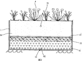
Fig. 1 is the structural representation of the utility model embodiment;
Fig. 2 be among Fig. 1 A-A to sectional view;
Fig. 3 is the structural representation of one-level water distribution pipe network among the utility model embodiment;
Fig. 4 is the catchment structural representation of pipe network of secondary among the utility model embodiment;
Fig. 5 is the catchment structural representation of pipe network of lower floor among the utility model embodiment;
Fig. 6 is cloth water branch among the utility model embodiment, catchment branch and the lower floor ramose sectional view that catchments;
Fig. 7 is the side elevational view of Fig. 5;
Fig. 8 is the partial enlarged drawing of Fig. 3;
Fig. 9 is the structural representation of water eliminator among the utility model embodiment.
Embodiment
Embodiment describes in further detail the utility model below in conjunction with accompanying drawing.
As Fig. 1~shown in Figure 9, the artificial swamp that this is used to dispose of sewage includes pond body 1, fills out artificial substratum, water distribution system, water gathering system, the pump well 3 that is located in the pond body 1 and is grown in plant 4 on the artificial substratum;
Wherein, about being isolated into by a watertight insulation 2, described pond body 1 is respectively two subregions of one-level cloth pool 11 and secondary catchment area 12, this pond body total depth is 1.0m, about two subregions press distribution in 60%: 40% that area is pressed the total area respectively, and leave the gap between this watertight insulation 2 and pond body 1 bottom, two subregion bottoms are interconnected, artificial substratum in this one-level cloth pool 11 is followed successively by pebble bed 51 from bottom to up, filtering layer 53 and coarse sands layer 54, and fill out the artificial substratum of establishing in the described secondary catchment area 12, be followed successively by pebble bed 51 from bottom to up, melon seeds lamella 52, filtering layer 53 and coarse sands layer 54, wherein, the growth of described coarse sands layer 54 as long as enough root systems of plant distribute, described filtering layer 53 adopts nylon net cloth, referring to Fig. 1 and Fig. 2;
As Fig. 1, Fig. 2 and shown in Figure 3, described water distribution system is the one-level water distribution pipe network 6 that is arranged among 11 medium-sand seams 54 of one-level cloth pool, its be laid on from described coarse sands layer 54 surperficial 0.1m apart from part, this one-level water distribution pipe network 6 includes a water-in 61, coupled logical water distribution is responsible for 62, being connected this water distribution is responsible on 62 and its vertically disposed cloth water branch 63 and the terminal washpipe 64 that has sewage draining exit 65 relatively, wherein, this washpipe 64 is connected with cloth water branch 63 ends and the 63 vertical settings of relative cloth water branch, for strengthening the water distribution person in charge 62 and the connectivity of washpipe 64 in the body end, between the two ends of the water distribution person in charge 62 and washpipe 64, respectively be connected with a cloth water branch 63, and, described water distribution is responsible for 62, cloth water branch 63, all have the water distribution aperture on the washpipe 64, the set-up mode of described water distribution aperture on body is all identical, with cloth water branch 63 is example, as shown in Figure 6 and Figure 7, water distribution aperture 63a on the described cloth water branch 63 is opened in the both sides of cloth water branch 63 bodys, have two water distribution aperture 63a up and down, and all be positioned at below the horizontal center line of body;
And, that end the described cloth water branch 63 close water distributions persons in charge 62 is provided with water eliminator 66, have aperture 66a on this water eliminator 66, the high and low position of aperture 66a can be made accommodation according to the size of flow on this water eliminator 66, and cloth water branch 63 offers inspection port 67 at the top of water eliminator 66 front ends, and generally speaking, this inspection port 67 is closed, when needing to take out water eliminator 66, just open this inspection port 67, referring to Fig. 3, Fig. 8 and Fig. 9;
As Fig. 1, Fig. 2 and shown in Figure 4, described water gathering system is to be distributed in secondary among 12 medium-sand seams 54 of the secondary catchment area pipe network 7 that catchments, its be laid on from coarse sands layer 54 surperficial 0.3m apart from part, this secondary pipe network 7 that catchments includes a water outlet 71, the straight person in charge 72 that catchments catchments with relative this and is responsible for 72 a plurality of branches 73 that catchment connected vertically, described water outlet 71, catchment be responsible for 72 and each catchment and be communicated with each other between the branch 73, and the catchment height of pipe network 7 of this secondary is lower than the height of one-level water distribution pipe network 6, wherein, the catchment water outlet 71 of pipe network 7 of this secondary is connected with pump well 3, identical with the design of described cloth water branch 63, as shown in Figure 5 and Figure 6, have the aperture that catchments in this branch 73 that catchments, it is opened in the both sides of branch's 73 bodys that catchment, have two apertures that catchment up and down, and all be positioned at below the horizontal center line of body;
As Fig. 1, Fig. 2 and shown in Figure 5, the bottom center of described pond body 1 is longitudinally sunk, and be equipped with lower floor's header 8 in pond body 1 bottom, its be laid on from pond body 1 bottom 0.1m apart from part, this lower floor's header 8 includes a central longitudinal to collection tube 81, the vertical collection tube 84 in an edge on many lateral collection pipes 82 that coupled logical and shape and pond body 1 bottom match and the two-port that is connected to these a plurality of lateral collection pipes 82, wherein, this central longitudinal just in time is arranged on the sagging place 13 of pond body 1 central authorities to collection tube 81, and its end has a sewage draining exit 83 that is connected with the external world, this central longitudinal is to collection tube 81, all have aperture on the vertical collection tube 84 in lateral collection pipe 82 and edge, identical with the design of described cloth water branch 63, as shown in Figure 6 and Figure 7, this aperture is opened in the both sides of body, have two apertures up and down, and all be positioned at below the horizontal center line of body.
Artificial swamp of the present utility model is when works better, sewage arrives water collecting basin through septic tank, pass through pretreatment system then, treated post precipitation is by the one-level cloth pool 11 of water pump lifting to artificial swamp, water-in 61 by one-level water distribution pipe network 6 in the artificial swamp enters, water distribution through one-level water distribution pipe network 6 is responsible for 62, cloth water branch 63 and washpipe 64 are distributed among the artificial substratum, form undercurrent, filter through artificial substratum, absorption, ion-exchange, absorption conversion of plant and the decomposition of microorganism, make sewage purification become water purification, then, water purification flows to the right from the left side of pond body 1 bottom, promptly flow to secondary catchment area 12 from one-level cloth pool 11, pass through the filtration of artificial substratum again, decomposing, purifying, the branch 73 that catchments that is catchmented in the pipe network 7 by secondary collects, and gathers and is outputed among the pump well 3 by water outlet 71, through top processing water later, can reach national secondary discharge standard;
One-level water distribution pipe network 6 of the present utility model is when flushing, open the inspection port 67 in the one-level water distribution pipe network 6, water eliminator 66 is taken out, current enter from the water-in 61 of one-level water distribution pipe network 6, positive each cloth water branch 63 of flushing is then gathered by washpipe 64 and flows to sewage draining exit 65;
Lower floor of the present utility model header 8 is when flushing, current also enter from the water-in 61 of one-level water distribution pipe network 6, at this moment, sewage draining exit 65 sealings of one-level water distribution pipe network 6, simultaneously, water eliminator 66 takes out, current are distributed in the artificial substratum by the cloth water branch 63 of one-level water distribution pipe network 6, pass through coarse sands layer 54 successively, filtering layer 53, pebble bed 51, dirt in these layers just flows down thereupon, be aggregated into the sagging place 13 of pond body 1 bottom, and collect and be discharged to the external world to collection tube 81 from sewage draining exit 83 by the central longitudinal of lower floor's header 8, the vertical collection tube 84 in lateral collection pipe 82 and edge then help is collected in the sewage at other positions, pond body 1 bottom, and the mud of last sewage draining exit 83 outputs concentrates outward transport.