CN2608195Y - Movable arm six hole processing universal machine tool - Google Patents
Movable arm six hole processing universal machine tool Download PDFInfo
- Publication number
- CN2608195Y CN2608195Y CN 02234472 CN02234472U CN2608195Y CN 2608195 Y CN2608195 Y CN 2608195Y CN 02234472 CN02234472 CN 02234472 CN 02234472 U CN02234472 U CN 02234472U CN 2608195 Y CN2608195 Y CN 2608195Y
- Authority
- CN
- China
- Prior art keywords
- slide unit
- cross slid
- workbench
- swing arm
- block
- Prior art date
- Legal status (The legal status is an assumption and is not a legal conclusion. Google has not performed a legal analysis and makes no representation as to the accuracy of the status listed.)
- Expired - Fee Related
Links
Images
Landscapes
- Drilling And Boring (AREA)
Abstract
The utility model discloses a movable arm six hole processing universal machine tool, in which six numerical control cross slipways are arranged symmetrically on both sides of the worktable, including cutting tool boring bar, boring heads, cross slipways, central base, worktable, welding fixture, and working pieces which are sequentially and rigidly connected with hanging rotating centralized control box, electrical control cabinet, numerical system, cooling station as well as pipes. All cross slipways are the ball screw drive, among which the upper slipway is under ac servo numerical control, the lower one digitally displays detected displacement, the upper face of guide way is covered with plastics belt, all cross slipways and boring heads have their own independent lubricating system. By moving cross slipway, adjusting positioning V type iron, adjusting upper slipway feeding stroke and velocity, changing cutting tool boring bar, locking adjustment of adjustable bearing and alignment V type iron on level, further testing by testing part of the boring bar, work pieces of different type can be machined in accordance with concrete requirements.
Description
Affiliated technical field
The utility model relates to the lathe of engineering machinery-loading arm hole boring shaving metal cutting processing, especially is suitable for the above many kinds yarn row spare processing of two kinds of swing arm, uses this equipment can finish swing arm parts integral body and veneer whole hole processing.
Background technology
Present known swing arm six holes processing be (1) earlier with the swing arm veneer two stacks on the common digital display floor type boring machine or on common digital display lands to boring one group one group ground divide and process for three times by running coordinate.(2) (parts) boring on the boring special plane goes out six holes after the swing arm integral solder, and the swing arm of each model all will be made a special plane, and this brings difficulty for loading machine less volume and more variety production characteristics and new product development, because its cost and floor space even may not.
Summary of the invention
In order to solve the problem that each model swing arm can not be processed on same lathe, the utility model provides a kind of swing arm six hole processor beds, and this lathe can not only be finished the processing eventually of yarn row swing arm parts six holes, and can finish the processing eventually of each model swing arm veneer hole.
The technical scheme that its technical problem that solves the utility model adopts is: arrange that in the workbench bilateral symmetry six cross slid platforms (need not to swing arm monotype ironworker dress, each increases the location clamping at veneer medial surface two places, the workpiece centering is united by the numerical control yarn, with the boring bar end checking part from the centering machining hole, move the holes for clamping outside two circular arc self-centerings by the both sides v block, guarantee that different model workpiece two side holes position of center line is all the time on same horizontal plane, by the further centering of each boring bar end checking part, the locking v block is finished workpiece processing.
The utility model beneficial effect is: can not only finish the processing eventually of each model swing arm parts six hole on an equipment, and can finish the processing eventually of each model swing arm veneer hole, satisfy many kinds each batch and new product development needs, improve work efficiency, reduce processing and manufacturing cost, improve the crudy of part, promote product specification.
Description of drawings
The utility model is described in further detail below in conjunction with drawings and Examples.
Accompanying drawing 1 is the utility model scheme arrangement figure.
Accompanying drawing 2 is location adjustable v-type iron construction figure.
Accompanying drawing 3 is horizontal centering v block structure chart.
Accompanying drawing 4 is a clamp fixture structure member layout drawing.
The specific embodiment
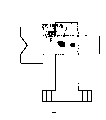
In Fig. 1, the II hole is that the punching axle is with the v block locating hole for the rocking arm installing hole, all boring heads are standarized component, each boring head, slide unit by separately independently lubricating arrangement unify fuel feeding, the laminating processing of the upper rail of slide unit, thus fully guarantee the reliability and the accuracy of numerical control displacement, the stability of machining, cooling stations also can be arranged in the workbench center base.The wide 1540mm of the maximum long 3500mm of processing work (in two stomidium centre-to-centre spacing) of lathe, the wide 1062mm of the long 1500mm of minimum process workpiece (in two stomidium centre-to-centre spacing).
In Fig. 1, workbench and center base (18), boring bar and cutter (20), boring head (21), servo digital control gearbox (22) moves up and down the balance weight mechanism (23) of slide plate, reaching up and down of the vertical stroke 630mm of stroke 250mm vertically moves cross slid platform (24) up and down, the horizontal cross slid platform (25) of vertical stroke 500mm infeed stroke 630mm, electrical control cubicles (26), cooling stations (27).
In location adjustable v-type iron embodiment shown in Figure 2, attachment bolt (1) passes bearing (2) chute and is fixed on the V-type base iron (3), adjust cushion block (4) and make different-thickness according to veriform part, and mark, cushion block (4) is adjusted in degree of tightness attachment bolt (1) transposing.The middle part is provided with gathering sill below the bearing (2), and both sides are provided with connecting hole. be fixed on the workbench by spiral shell inspection and T type grooved screw.
In horizontal centering v block embodiment shown in the accompanying drawing 3, centering v block (5) drives core shift camshaft (9) clamping work pieces by handgrip (8), soket head cap screw (10) locking v block (5).[band two-sided wedge of section (6) and soket head cap screw (7) double dot dash line structure are another form of clamping work pieces among the figure].Bearing (11) footing hole is fixed on the workbench by bolt T type groove screw.
In clamp fixture arrangements of components figure shown in the figure (4), accompanying drawing 3 horizontal centering v block parts (12), adjustable support (13), the guide (14) of accompanying drawing 2 location adjustable v-type iron parts, positioning core axle (15), accompanying drawing 2 location adjustable v-type iron parts (16), compacting part (17), workbench (18) on it according to processing different model part tooling needs, be processed with cross T type groove in length and breadth, workpiece (19) also can just put (be the rocking arm hole up, among the figure with swing arm counter put be the rocking arm hole below draw).(annotate: processing swing arm veneer is considered its stability, need to increase the location, side and clamp position shown in the figure sharp head.)
Claims (6)
1. swing arm six holes process universal machine tools, in the workbench both sides, six cross slid platforms of symmetric arrangement, two is vertical cross slid platform in the middle of the both sides, and four at two ends, both sides are horizontal cross slid platform, and slide unit slide (wing base) is rigidly connected with workbench (center base) under each cross slid platform, respectively adorn a boring head on the last slide unit slide plate, on the boring head main shaft boring bar is housed, boring bar is provided with foremost tests (looking for) positive portion, and slide unit is the feeding slide unit on the cross slid platform, slide unit is a pitch-row location slide unit down; Part, workbench center is provided with adjustable (replacing) location v block (the swing arm veneer is not needed), and the processing swing arm is located thereon with rocking arm installing hole punching axle; Workbench both ends horizontal v block centering workpiece, make each model workpiece two ends centerline hole all the time in same horizontal plane, relation between each parts is: cutter, boring bar, boring head, cross slid platform, center base, workbench, frock, workpiece order rigid attachment, it is characterized in that: workbench (center base) bilateral symmetry be rigidly connected the size each two wing base, the horizontal cross slid platform of one end and a middle vertical cross slid platform are arranged on the big wing base, the horizontal cross slid platform of the other end is arranged on the little wing base, but slide unit vertical displacement movement under middle two vertical cross slid platforms, be provided with balance weight mechanism, slide unit can move horizontally under four the horizontal cross slid platforms in two ends, slide unit feed distance servo digital control on each cross slid platform, feed speed adopts frequency control, following slide unit can adopt mechanical driving device, vernier scale or digital display or NC inspecting displacement, if manually, the crawl fine setting, following slide unit is provided with the initial position fix piece, its when assembling according to a routine or maximum or minimum aperture apart from setting, and on specification, indicate, each slide unit adopts ball screw transmission, the laminating processing of upper rail face of slide unit; Boring head is installed on the upper slide of each cross slid platform, moves with slide plate, and boring head is standarized component, changes rotating speed and adopts change gear; Boring bar is contained on the boring head main shaft, and boring bar is provided with checking part foremost, and cutter is contained in the tool bore of boring bar front end, workpiece varying aperture transposing cutter, boring bar; Be provided with guide in part, workbench length direction center, make location v block (adjustable or replacing) make certain limit thereon and do directed moving, location back by Bolt Connection on workbench, the processing swing arm is located on v block with rocking arm installing hole punching axle, and location adjustable v-type iron is made up of attachment bolt, the bearing that has gathering sill, V-type base iron, adjustment cushion block; The horizontal centering v block parts at workbench two ends on workbench, are locked by core shift cam or local clamping of wedge with Bolt Connection by the four hole outer arc self-centerings of workpiece two ends, and the boring bar checking part is further verified; Electrical control cubicles is provided with separately; Can be provided with separately or be arranged in the workbench center base as the need cooling stations.
2. swing arm six hole processor beds according to claim 1, it is characterized in that: the slide plate of the slide of slide unit and following slide unit is an overall structure on the cross slid platform, each manual fine-tuning realizes that by handwheel driven gear tooth bar or worm-and-wheel gear it installs in slide slide plate side.
3. swing arm six hole processor beds according to claim 1, the height that it is characterized in that locating v block is different because of the different model workpiece with horizontal level, adjusts cushion block or replacing and directed mobile v block by transposing and realizes.
4. swing arm six hole processor beds according to claim 1 is characterized in that horizontal centering v block clamps with two side holes external arc location, and self-centering guarantees that different model workpiece two ends four center lines are all the time on a horizontal plane.
5. swing arm six hole processor beds according to claim 1 is characterized in that two-sided or single face is arranged processing swing arm veneer (the stackable processing of workpiece), need not locate v block, increase the location at inboard two places of veneer and clamp, and realize the processing of veneer hole.
6. swing arm six hole processor beds according to claim 1, in the middle of it is characterized in that on the feeding slide unit of two vertical cross slid platforms lower guideway be the double-swallow-tail shape structure.
Priority Applications (1)
| Application Number | Priority Date | Filing Date | Title |
|---|---|---|---|
| CN 02234472 CN2608195Y (en) | 2002-05-09 | 2002-05-09 | Movable arm six hole processing universal machine tool |
Applications Claiming Priority (1)
| Application Number | Priority Date | Filing Date | Title |
|---|---|---|---|
| CN 02234472 CN2608195Y (en) | 2002-05-09 | 2002-05-09 | Movable arm six hole processing universal machine tool |
Publications (1)
| Publication Number | Publication Date |
|---|---|
| CN2608195Y true CN2608195Y (en) | 2004-03-31 |
Family
ID=34149079
Family Applications (1)
| Application Number | Title | Priority Date | Filing Date |
|---|---|---|---|
| CN 02234472 Expired - Fee Related CN2608195Y (en) | 2002-05-09 | 2002-05-09 | Movable arm six hole processing universal machine tool |
Country Status (1)
| Country | Link |
|---|---|
| CN (1) | CN2608195Y (en) |
Cited By (10)
| Publication number | Priority date | Publication date | Assignee | Title |
|---|---|---|---|---|
| CN100351036C (en) * | 2005-12-28 | 2007-11-28 | 夏士林 | Digital controlled tracing welding machine tool |
| CN102099150A (en) * | 2008-07-16 | 2011-06-15 | 哈恩和特斯基工件指数有限商业两合公司 | Machine-tool |
| CN101653898B (en) * | 2009-09-29 | 2011-06-15 | 浙江宇太汽车零部件制造有限公司 | Process and device for finely processing rocking arm inner hole |
| CN102847974A (en) * | 2011-09-26 | 2013-01-02 | 湖北汇科数控组合机电装备有限公司 | Multiple-spindle boring machine |
| CN103386499A (en) * | 2013-08-06 | 2013-11-13 | 湘潭市汇丰设备制造有限公司 | Efficient numerical control boring and milling machine |
| CN103862079A (en) * | 2014-03-21 | 2014-06-18 | 上虞市东杰冷却塔有限公司 | Bidirectional drilling machine |
| CN105436553A (en) * | 2015-12-29 | 2016-03-30 | 天津滨海光热跟踪技术有限公司 | Cantilever processing machine tool |
| CN106735427A (en) * | 2015-06-09 | 2017-05-31 | 吴小再 | The rocker for being capable of achieving 360 ° of torsion punch operations bores punching tooling device |
| CN107363285A (en) * | 2017-07-12 | 2017-11-21 | 邓干平 | A kind of large-sized numerical control combination drilling machine and coordinate transformation method |
| CN108544247A (en) * | 2018-05-31 | 2018-09-18 | 亿达日平机床有限公司 | Horizontal shifting moves case apparatus certainly |
-
2002
- 2002-05-09 CN CN 02234472 patent/CN2608195Y/en not_active Expired - Fee Related
Cited By (15)
| Publication number | Priority date | Publication date | Assignee | Title |
|---|---|---|---|---|
| CN100351036C (en) * | 2005-12-28 | 2007-11-28 | 夏士林 | Digital controlled tracing welding machine tool |
| CN102099150B (en) * | 2008-07-16 | 2015-09-30 | 哈恩和特斯基工件指数有限商业两合公司 | Lathe |
| CN102099150A (en) * | 2008-07-16 | 2011-06-15 | 哈恩和特斯基工件指数有限商业两合公司 | Machine-tool |
| CN101653898B (en) * | 2009-09-29 | 2011-06-15 | 浙江宇太汽车零部件制造有限公司 | Process and device for finely processing rocking arm inner hole |
| CN102847974A (en) * | 2011-09-26 | 2013-01-02 | 湖北汇科数控组合机电装备有限公司 | Multiple-spindle boring machine |
| CN103386499A (en) * | 2013-08-06 | 2013-11-13 | 湘潭市汇丰设备制造有限公司 | Efficient numerical control boring and milling machine |
| CN103862079A (en) * | 2014-03-21 | 2014-06-18 | 上虞市东杰冷却塔有限公司 | Bidirectional drilling machine |
| CN103862079B (en) * | 2014-03-21 | 2016-04-27 | 上虞市东杰冷却塔有限公司 | A kind of two-way drilling machine |
| CN106735427A (en) * | 2015-06-09 | 2017-05-31 | 吴小再 | The rocker for being capable of achieving 360 ° of torsion punch operations bores punching tooling device |
| CN106735427B (en) * | 2015-06-09 | 2018-09-11 | 江苏奔宇车身制造有限公司 | The radial drill punching tooling device of 360 ° of torsion punch operations can be achieved |
| CN105436553A (en) * | 2015-12-29 | 2016-03-30 | 天津滨海光热跟踪技术有限公司 | Cantilever processing machine tool |
| CN107363285A (en) * | 2017-07-12 | 2017-11-21 | 邓干平 | A kind of large-sized numerical control combination drilling machine and coordinate transformation method |
| CN107363285B (en) * | 2017-07-12 | 2019-06-07 | 邓干平 | A kind of large-sized numerical control combination drilling machine and coordinate transformation method |
| CN108544247A (en) * | 2018-05-31 | 2018-09-18 | 亿达日平机床有限公司 | Horizontal shifting moves case apparatus certainly |
| CN108544247B (en) * | 2018-05-31 | 2023-08-29 | 亿达日平机床有限公司 | Automatic box changing device for horizontal transverse movement |
Similar Documents
| Publication | Publication Date | Title |
|---|---|---|
| CN2865936Y (en) | Main shaft moving digital control lathe | |
| KR101921227B1 (en) | Horizontal type multi spindle machining center | |
| CN106625030A (en) | Composite flexible manufacturing unit | |
| CN2608195Y (en) | Movable arm six hole processing universal machine tool | |
| CN103551627B (en) | The deep hole processing method of gantry pentahedron Digit Control Machine Tool | |
| CN101347911B (en) | Numerical control reverse direction machining aggregate machinery | |
| CN105127842A (en) | Precise vertical control system of machining center | |
| CN207615668U (en) | A kind of numerical control movable post vertical lathe | |
| CN201264181Y (en) | Numerical control reverse direction machining aggregate machinery | |
| CN206493172U (en) | A kind of multiaspect combined machine | |
| CN218503852U (en) | Numerical control milling machine | |
| CN106271679A (en) | A kind of pentahedron composite processing machine tool | |
| CN105149968A (en) | High-precision stable precision vertical machining center | |
| CN217143309U (en) | Processing machine tool | |
| CN201889490U (en) | Milling machine working device specially for guiding rail | |
| CN2614100Y (en) | Bucket triaxial rigid boring lathe | |
| CN214641754U (en) | Horizontal machining center | |
| CN107971503A (en) | A kind of numerical control movable post vertical lathe | |
| CN212043492U (en) | Serial-type many main shafts machining center | |
| CN211539550U (en) | Special boring device for headstock and box body of numerical control lathe | |
| CN112975447A (en) | Horizontal machining center | |
| CN105563122A (en) | Profile machining center | |
| CN219151588U (en) | Inverted numerical control lathe structure | |
| CN204913290U (en) | Accurate vertical machining center of firm type of high accuracy | |
| CN109822111A (en) | A kind of thin space horizontal multi-spindle numerical control lathe |
Legal Events
| Date | Code | Title | Description |
|---|---|---|---|
| C14 | Grant of patent or utility model | ||
| GR01 | Patent grant | ||
| C19 | Lapse of patent right due to non-payment of the annual fee | ||
| CF01 | Termination of patent right due to non-payment of annual fee |