CN2305525Y - Reciprocating and circular motion reversable switching equipment - Google Patents
Reciprocating and circular motion reversable switching equipment Download PDFInfo
- Publication number
- CN2305525Y CN2305525Y CN 97250867 CN97250867U CN2305525Y CN 2305525 Y CN2305525 Y CN 2305525Y CN 97250867 CN97250867 CN 97250867 CN 97250867 U CN97250867 U CN 97250867U CN 2305525 Y CN2305525 Y CN 2305525Y
- Authority
- CN
- China
- Prior art keywords
- circular
- axle
- slideway
- slide block
- cylindrical shape
- Prior art date
- Legal status (The legal status is an assumption and is not a legal conclusion. Google has not performed a legal analysis and makes no representation as to the accuracy of the status listed.)
- Expired - Fee Related
Links
Images


Abstract
The utility model relates to a reciprocating and circular motion reversible switching device, composed of a circular inner axle, a cylindrical sliding block, an outer cylinder and a sliding bead, wherein, the sliding bead is arranged in a circular hole on the cylindrical sliding block, the inner end of the sliding bead is connected with a continuous slide way with an annular sloped face on the surface of the circular inner axle, and the outer end of the sliding ball is connected with an axial slide way on the inner wall of the outer cylinder. The utility model can switch a reciprocating motion to a circular motion and can also switch the circular motion to the reciprocating motion, and the utility model not only has simple manufacture process, but also enhances the mechanical efficiency.
Description
The utility model relates to a kind of reciprocal and reversible conversion equipment of circular movement.
Reciprocal and the reversible conversion equipment of circular movement that uses at present adopts bent axle mostly, and its structure is complicated, the cost height, and mechanical efficiency is low.
The purpose of this utility model is to provide a kind of volume little, and preparation process is simple, the reciprocal and reversible conversion equipment of circular movement that efficient is high.
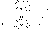
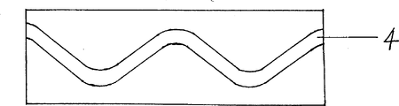
The utility model is by axle (1) in circular, cylindrical shape slide block (2), urceolus (3) and sliding pearl (9) composition.There is a continuous circular shape inclined-plane slideway (4) on axle (1) surface in circular, and circular interior axle (1) one end is fixed with output shaft (5), and there is keyway (6) output shaft (5) outer end; Have on the cylindrical shape slide block (2) two toward each other in axisymmetric circular hole; Urceolus (3) inwall have two toward each other in axisymmetric axial slideway (8).
Fig. 1 is reciprocal and the reversible conversion equipment sectional drawing of circular movement;
Fig. 2 is circular interior axle schematic representation;
Fig. 3 is a cylindrical shape slide block schematic representation;
Fig. 4 is the urceolus schematic representation.
Fig. 5 is that cylindrical shape slide block A-A is to sectional view;
Fig. 6 is the surperficial slideway unfolded drawing of circular interior axle.
In conjunction with the accompanying drawings structural principle of the present utility model is described further.
Axle (1) is sleeved in the cylindrical shape slide block (2) in circular, and the inner of two sliding pearls (9) joins by the slideway (4) on the axle (1) in circular hole (7) on the cylindrical shape slide block (2) and the circle; Cylindrical shape slide block (2) is sleeved in the urceolus (3), and outer end of two sliding pearls (9) and the axial slideway (8) on the outer tube inner wall join.
If convert linear reciprocating motion to circular movement, can execute an external force in cylindrical shape slide block (2), because the restriction of urceolus (3) two axial slideways of inwall (8), make tubular slide block (2) to do reciprocating linear motion along slideway (8), when cylindrical shape slide block (2) was reciprocating, external force acted on the continuous circular shape inclined-plane slideway (4) of circular interior axle (1) by sliding pearl (9), be equivalent to the power to (1) rotation of axle in circular, axle (1) rotates in the feasible circle.If it is reciprocating that the cylindrical shape slide block continues, interior axle also just continues to do circular movement, thereby realizes that to-and-fro motion changes circular movement into.
If circular movement is changed linear reciprocating motion, can in circular, execute an external force on the axle (1), make circular interior axle (1) make circular movement, this external force acts on the sliding pearl (9) by the continuous circular shape inclined-plane slideway (4) on the axle (1) in circular, act on the cylindrical shape slide block (2) by sliding pearl (9) again, because the restriction of the axial slideway of urceolus (3) inwall (8) makes cylindrical shape slide block (3) under the drive of sliding pearl (9), can only do reciprocating linear motion in urceolus (3).Thereby realized that circular movement is converted to to-and-fro motion.
The number of gradient, length and the Qu Feng of the continuous circular shape inclined-plane slideway (4) in the utility model circle on the axle (1), can design according to the needs that reality is used, the section configuration of slideway can be multiple geometrical shape, as arc, trapezoidal, the axial slideway of urceolus (3) inwall also can be multiple geometrical shape, as arc, trapezoidal.Upward the gradient and the length of adjacent inclined-plane slideway can be different for axle (1) in circular, but must be symmetrical, and the summit of corresponding Qu Feng also must be on sustained height mutually.Bent peak can be the even number more than two or two.Qu Fengyue is many, and when to-and-fro motion converted circular movement to, the rotating speed of output was also just slow more; Otherwise when the circular movement movement conversion became to-and-fro motion, reciprocating speed was also just fast more.
The utility model is compared with bent axle, and the volume of machinery is reduced, and preparation process is simple, and owing to axle in circular uses inclined plane principle, the inclined-plane can be laborsaving, the efficient when having improved mutual the conversion.
Claims (4)
1, a kind of reciprocal and reversible conversion equipment of circular movement, form by axle (1), cylindrical shape slide block (2), urceolus (3) and sliding pearl (9) in circular, it is characterized in that there is a continuous circular shape inclined-plane slideway (4) on circular interior axle (a 1) surface, cylindrical shape slide block (2) have two toward each other in axisymmetric circular hole (7), urceolus (3) inwall have two toward each other in axisymmetric axial slideway (8); Axle (1) is sleeved in the cylindrical shape slide block (2) in circular, and the inner of two sliding pearls (9) joins by the slideway (4) on the axle (1) in circular hole (7) on the cylindrical shape slide block (2) and the circle; Cylindrical shape slide block (2) is sleeved in the urceolus (3), and outer end of two sliding pearls (9) and the axial slideway (8) on the outer tube inner wall join.
2, as described in the claim l back and forth with the reversible conversion equipment of circular movement, it is characterized in that circular in the section configuration of annular slope slideway (4) on spool (1) can be arc or trapezoidal.
3, the reciprocal according to claim 1 and reversible conversion equipment of circular movement is characterized in that the section configuration of the axial slideway (8) on urceolus (3) inwall can be an arc or trapezoidal.
4, as claimed in claim 1 or 2 back and forth with the reversible conversion equipment of circular movement, it is characterized in that circular in bent peak on the surperficial continuous circular shape inclined-plane slideway (4) of axle (1) even number more than 2 or 2 can be arranged.
Priority Applications (1)
| Application Number | Priority Date | Filing Date | Title |
|---|---|---|---|
| CN 97250867 CN2305525Y (en) | 1997-08-22 | 1997-08-22 | Reciprocating and circular motion reversable switching equipment |
Applications Claiming Priority (1)
| Application Number | Priority Date | Filing Date | Title |
|---|---|---|---|
| CN 97250867 CN2305525Y (en) | 1997-08-22 | 1997-08-22 | Reciprocating and circular motion reversable switching equipment |
Publications (1)
| Publication Number | Publication Date |
|---|---|
| CN2305525Y true CN2305525Y (en) | 1999-01-27 |
Family
ID=33957308
Family Applications (1)
| Application Number | Title | Priority Date | Filing Date |
|---|---|---|---|
| CN 97250867 Expired - Fee Related CN2305525Y (en) | 1997-08-22 | 1997-08-22 | Reciprocating and circular motion reversable switching equipment |
Country Status (1)
| Country | Link |
|---|---|
| CN (1) | CN2305525Y (en) |
Cited By (6)
| Publication number | Priority date | Publication date | Assignee | Title |
|---|---|---|---|---|
| WO2006108342A1 (en) * | 2005-04-11 | 2006-10-19 | Liang Fang | A grooved cam |
| CN1300489C (en) * | 2004-11-04 | 2007-02-14 | 西南石油学院 | Screw reversing mechanism in a state of rolling friction |
| CN104405846A (en) * | 2014-11-08 | 2015-03-11 | 曹成 | Novel mechanical telescopic device |
| CN112145110A (en) * | 2020-11-02 | 2020-12-29 | 东北石油大学 | Hydraulic pulse oscillation device |
| CN112253024A (en) * | 2020-12-08 | 2021-01-22 | 中国石油天然气集团有限公司 | Oil pipe sand removal device and sand removal method for oil and gas well |
| CN112847417A (en) * | 2020-12-31 | 2021-05-28 | 洛阳尚奇机器人科技有限公司 | Mechanical arm tail end execution device |
-
1997
- 1997-08-22 CN CN 97250867 patent/CN2305525Y/en not_active Expired - Fee Related
Cited By (9)
| Publication number | Priority date | Publication date | Assignee | Title |
|---|---|---|---|---|
| CN1300489C (en) * | 2004-11-04 | 2007-02-14 | 西南石油学院 | Screw reversing mechanism in a state of rolling friction |
| WO2006108342A1 (en) * | 2005-04-11 | 2006-10-19 | Liang Fang | A grooved cam |
| CN104405846A (en) * | 2014-11-08 | 2015-03-11 | 曹成 | Novel mechanical telescopic device |
| CN112145110A (en) * | 2020-11-02 | 2020-12-29 | 东北石油大学 | Hydraulic pulse oscillation device |
| CN112145110B (en) * | 2020-11-02 | 2022-08-30 | 东北石油大学 | Hydraulic pulse oscillation device |
| CN112253024A (en) * | 2020-12-08 | 2021-01-22 | 中国石油天然气集团有限公司 | Oil pipe sand removal device and sand removal method for oil and gas well |
| CN112253024B (en) * | 2020-12-08 | 2023-03-24 | 中国石油天然气集团有限公司 | Oil pipe sand removal device and sand removal method for oil and gas well |
| CN112847417A (en) * | 2020-12-31 | 2021-05-28 | 洛阳尚奇机器人科技有限公司 | Mechanical arm tail end execution device |
| CN112847417B (en) * | 2020-12-31 | 2022-07-29 | 洛阳尚奇机器人科技有限公司 | Mechanical arm tail end execution device |
Similar Documents
| Publication | Publication Date | Title |
|---|---|---|
| CN2305525Y (en) | Reciprocating and circular motion reversable switching equipment | |
| CN111346547A (en) | New material agitating unit that compounding is more even and automatic change | |
| CN102515053A (en) | Propping device of overlong rotary handle | |
| CN210371044U (en) | Body-building power generation device | |
| CN101183840A (en) | Magnetic energy engine | |
| CN210244817U (en) | Intermittent rotary sand table model | |
| CN108869675B (en) | Motion conversion device | |
| CN2506225Y (en) | Double-lever gearing electric toothbrush | |
| US20020047411A1 (en) | Series of force-enhancing powerful magnetic energy engine with high-speed | |
| CN220118581U (en) | Electric telescopic rod | |
| CN206364652U (en) | A kind of mechanical swing arm with boosting mechanism | |
| CN2252504Y (en) | Hand piston feeding dumpling machine | |
| CN217978612U (en) | Gardens are with multi-functional environmental protection street lamp of liftable | |
| CN212958165U (en) | Cambered surface lifting shaft for shower room | |
| CN216194218U (en) | Road diversion guiding device for highway engineering | |
| CN217795843U (en) | Microfluid mixing generating device | |
| CN218423653U (en) | Accurate transmission stable form sprayer | |
| CN219074016U (en) | Roller set for molding production of cone special-shaped pipe | |
| CN214248198U (en) | Magnetic suction type telescopic rotary tooth box structure | |
| CN2236577Y (en) | Cam drive inverter | |
| CN201531577U (en) | Axial slide rod reciprocating engine | |
| CN217206749U (en) | Power generation device based on lever and gravity wheel | |
| CN2240315Y (en) | Speed changer for electric rotation display table | |
| CN108582772B (en) | Basement slush mode 3D printer | |
| CN2129958Y (en) | Time regulated rotary plate ad board |
Legal Events
| Date | Code | Title | Description |
|---|---|---|---|
| C14 | Grant of patent or utility model | ||
| GR01 | Patent grant | ||
| C19 | Lapse of patent right due to non-payment of the annual fee | ||
| CF01 | Termination of patent right due to non-payment of annual fee |