CN219281239U - Jacking for building with high-strength structure - Google Patents
Jacking for building with high-strength structure Download PDFInfo
- Publication number
- CN219281239U CN219281239U CN202320905133.8U CN202320905133U CN219281239U CN 219281239 U CN219281239 U CN 219281239U CN 202320905133 U CN202320905133 U CN 202320905133U CN 219281239 U CN219281239 U CN 219281239U
- Authority
- CN
- China
- Prior art keywords
- fixedly connected
- jacking
- support
- strength structure
- sliding
- Prior art date
- Legal status (The legal status is an assumption and is not a legal conclusion. Google has not performed a legal analysis and makes no representation as to the accuracy of the status listed.)
- Active
Links
Images


Classifications
-
- Y—GENERAL TAGGING OF NEW TECHNOLOGICAL DEVELOPMENTS; GENERAL TAGGING OF CROSS-SECTIONAL TECHNOLOGIES SPANNING OVER SEVERAL SECTIONS OF THE IPC; TECHNICAL SUBJECTS COVERED BY FORMER USPC CROSS-REFERENCE ART COLLECTIONS [XRACs] AND DIGESTS
- Y02—TECHNOLOGIES OR APPLICATIONS FOR MITIGATION OR ADAPTATION AGAINST CLIMATE CHANGE
- Y02E—REDUCTION OF GREENHOUSE GAS [GHG] EMISSIONS, RELATED TO ENERGY GENERATION, TRANSMISSION OR DISTRIBUTION
- Y02E10/00—Energy generation through renewable energy sources
- Y02E10/50—Photovoltaic [PV] energy
Abstract
The utility model relates to the technical field of building construction and discloses a jacking for a building with a high-strength structure, which comprises a screw rod, wherein an adjusting nut is connected to the outer thread of the screw rod, a handle is fixedly connected to the outer part of the adjusting nut, a connecting ring is fixedly connected to the top wall of the screw rod, a support is fixedly connected to the top wall of the connecting ring, butt joint grooves are formed in the left side and the right side of the inside of the support, sliding grooves are formed in the left side and the right side of the support, limiting blocks are fixedly connected to the far sides of two connecting columns, a sliding groove is formed in the left side of the connecting columns, blocking bars are fixedly connected to the left end and the right end of the sliding groove, and clamping blocks are fixedly connected to the front side and the rear side of a spring. According to the utility model, the jacking supports can be fixed and limited in the use process, so that the jacking supports can be mutually matched, the jacking supports can be fixed and separated at any time, and the upper bearing limit of the jacking supports is improved.
Description
Technical Field
The utility model relates to the technical field of building construction, in particular to a jacking for a building with a high-strength structure.
Background
The jacking for building is as follows: the construction method is used in cooperation with the steel pipe and the scaffold in the construction process, plays roles in adjusting the heights of the scaffold and the pipe frame, balancing and supporting weights and bearing, is most used in the construction process of concrete pouring of plane construction enterprises, and is an indispensable tool in the present construction operation along with rapid development of real estate and three-dimensional traffic in recent years.
Most jacking at present often cooperate with the scaffold when using but a plurality of jacking are all fixed between the scaffold alone, do not basically carry out the effect that fixes and can't share each other between the jacking.
Disclosure of Invention
The utility model aims to solve the defects in the prior art, and provides a building jacking with a high-strength structure.
In order to achieve the above purpose, the present utility model adopts the following technical scheme: the utility model provides a jacking for building with high strength structure, includes the lead screw, the outside threaded connection of lead screw has adjusting nut, adjusting nut's outside fixedly connected with handle, the roof fixedly connected with go-between of lead screw, the roof fixedly connected with support of go-between, the inside left and right sides of support all is provided with the butt joint groove, the left and right sides of support all is provided with the sliding tray, the inside sliding connection of butt joint groove has the spliced pole, two the equal fixedly connected with stopper in looks far away one side of spliced pole, the inside spout that is provided with in the left side of spliced pole, the equal fixedly connected with blend stop in both ends about spout, the inside fixedly connected with erection column of spout, the inside sliding connection of erection column has the spring, the equal fixedly connected with fixture block in front and back both sides of spring.
As a further description of the above technical solution:
the clamping block penetrates through the sliding groove and is connected inside the sliding groove in a sliding mode.
As a further description of the above technical solution:
the barrier strips are connected to the left end and the right end of the clamping block in a sliding mode.
As a further description of the above technical solution:
the limiting block is connected inside the sliding groove in a sliding mode.
As a further description of the above technical solution:
the roof of lead screw runs through the inside fixed connection of go-between at the bottom middle part of support.
As a further description of the above technical solution:
the clamping block is connected inside the sliding groove in a sliding mode.
As a further description of the above technical solution:
the springs are fixedly connected to adjacent sides of the two clamping blocks.
The utility model has the following beneficial effects:
1. according to the utility model, through the cooperation of the components such as the connecting column, the clamping block, the limiting block, the butt joint groove and the like, the jacking can be connected with the scaffold and meanwhile can be mutually connected for sharing the whole bearing capacity, so that the upper bearing limit is improved.
Drawings
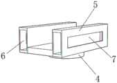
Fig. 1 is a front perspective view of a building jacking with a high-strength structure according to the present utility model;
fig. 2 is a right side perspective view of a building jacking having a high strength structure according to the present utility model;
FIG. 3 is a schematic diagram of a front view of a support structure of a building roof support with a high strength structure according to the present utility model;
fig. 4 is an exploded view of a connection column structure of a jacking for construction with a high-strength structure according to the present utility model.
Legend description:
1. a screw rod; 2. an adjusting nut; 3. a handle; 4. a connecting ring; 5. a support; 6. a butt joint groove; 7. a sliding groove; 8. a connecting column; 9. a limiting block; 10. a chute; 11. a barrier strip; 12. a mounting column; 13. a spring; 14. and (5) clamping blocks.
Detailed Description
The following description of the embodiments of the present utility model will be made clearly and completely with reference to the accompanying drawings, in which it is apparent that the embodiments described are only some embodiments of the present utility model, but not all embodiments. All other embodiments, which can be made by those skilled in the art based on the embodiments of the utility model without making any inventive effort, are intended to be within the scope of the utility model.
Referring to fig. 1-4, one embodiment provided by the present utility model is: the jacking for building with high-strength structure comprises a screw rod 1, an adjusting nut 2 is connected with the screw rod 1 through external threads, a handle 3 is fixedly connected with the adjusting nut 2, the handle 3 is designed to enable a user to rotate the adjusting nut 2 more quickly, a connecting ring 4 is fixedly connected with the top wall of the screw rod 1, a support 5 is fixedly connected with the top wall of the connecting ring 4, the connecting ring 4 is designed to increase the connection stability between the screw rod 1 and the support 5, the support 5 is designed to be connected with a top scaffold to support the scaffold, butt joint grooves 6 are formed in the left side and the right side of the inside of the support 5, butt joint reserved grooves are formed in the left side and the right side of the support 5 for enabling the structures among the supports 5 to be matched, sliding grooves 7 are formed in the left side and the right side of the support 5, connecting columns 8 are slidingly connected in the butt joint grooves 6, the design of the connecting column 8 is to butt joint and share the whole bearing capacity for a plurality of supports 5, the limiting blocks 9 are fixedly connected to the far sides of the two connecting columns 8, the design of the limiting blocks 9 is to cooperate with the sliding grooves 7 to prevent the connecting columns 8 from sliding out of the inside of the butt joint grooves 6 to play a limiting role on the device, the sliding grooves 10 are arranged in the left side of the connecting columns 8, the baffle strips 11 are fixedly connected to the left and right ends of the sliding grooves 10, the baffle strips 11 are designed to prevent the clamping blocks 14 from being ejected out of the sliding grooves 10 to limit the clamping blocks 14, the installation columns 12 are fixedly connected to the inside of the sliding grooves 10, the installation columns 12 are designed to prevent the springs 13 from deforming inside to protect and increase the stability of the springs 13, the inside of the installation columns 12 are slidably connected with the springs 13, the design of the springs 13 is to enable the two clamping blocks 14 to be butted into the sliding grooves 7 in the other support 5, the front side and the rear side of the spring 13 are fixedly connected with clamping blocks 14, and the clamping blocks 14 are designed to improve the connection stability between the two supports 5.
The fixture block 14 runs through the inside sliding connection of spout 10 in the inside of sliding tray 7, and such design is in order to let the device dock each other, and blend stop 11 sliding connection is at the both ends about fixture block 14, stopper 9 sliding connection in the inside of sliding tray 7, and the roof of lead screw 1 runs through the inside fixed connection of go-between 4 at the bottom middle part of support 5, and such design is in order to improve the butt joint stability between lead screw 1 and the support 5, and fixture block 14 sliding connection is in the inside of spout 10, and spring 13 fixed connection is in the adjacent one side of two fixture blocks 14.
Working principle: the staff puts into the scaffold with lead screw 1 then through the rotation that will rotate handle 3 through handle 3 thereby drive adjusting nut 2 and rotate, thereby drive the lead screw 1 through adjusting nut 2 and rotate and go up and down to the height of two upper and lower scaffolds and adjust, and spacing and fixed the top scaffold through the support 5 at top, dock in the inside butt joint groove 6 of every spliced pole 8 and nearby support 5 through pulling spliced pole 8 inside after the fixed, and dock with the same hand in the butt joint through spring 13 in the spout 10 in every spliced pole 8 to the fixture block 14 with the sliding tray 7 in the support 5, thereby dock between the support 5 and let the top support that supports the hand separately originally can carry out the bearing of mutually supporting, because the design both can utilize the top support to the fixed between the scaffold with liftable and through the interconnect between the support 5 after the installation is received, can improve holistic bearing force and easy operation convenient to use of whole bearing that can increase whole stability each other.
Finally, it should be noted that: the foregoing description is only illustrative of the preferred embodiments of the present utility model, and although the present utility model has been described in detail with reference to the foregoing embodiments, it will be apparent to those skilled in the art that modifications may be made to the embodiments described, or equivalents may be substituted for elements thereof, and any modifications, equivalents, improvements or changes may be made without departing from the spirit and principles of the present utility model.
Claims (7)
1. The utility model provides a jacking for building with high strength structure, includes lead screw (1), its characterized in that: external screw thread connection of lead screw (1) has adjusting nut (2), the outside fixedly connected with handle (3) of adjusting nut (2), the roof fixedly connected with go-between (4) of lead screw (1), roof fixedly connected with support (5) of go-between (4), the inside left and right sides of support (5) all is provided with docking groove (6), the left and right sides of support (5) all is provided with sliding tray (7), the inside sliding connection of docking groove (6) has spliced pole (8), two the equal fixedly connected with stopper (9) in looks far away side of spliced pole (8), the inside spout (10) that is provided with in left side of spliced pole (8), the equal fixedly connected with blend stop (11) in both ends about spout (10), the inside fixedly connected with erection column (12) of spout (10), the inside sliding connection of erection column (12) has spring (13), the inside fixedly connected with fixture block (14) around spring (13).
2. A building jacking having a high strength structure as claimed in claim 1, wherein: the clamping block (14) penetrates through the sliding groove (10) and is connected inside the sliding groove (7) in a sliding mode.
3. A building jacking having a high strength structure as claimed in claim 1, wherein: the blocking strips (11) are connected to the left end and the right end of the clamping block (14) in a sliding mode.
4. A building jacking having a high strength structure as claimed in claim 1, wherein: the limiting block (9) is connected inside the sliding groove (7) in a sliding mode.
5. A building jacking having a high strength structure as claimed in claim 1, wherein: the top wall of the screw rod (1) penetrates through the inner part of the connecting ring (4) and is fixedly connected with the middle part of the bottom end of the support (5).
6. A building jacking having a high strength structure as claimed in claim 1, wherein: the clamping block (14) is connected inside the sliding groove (10) in a sliding mode.
7. A building jacking having a high strength structure as claimed in claim 1, wherein: the springs (13) are fixedly connected to adjacent sides of the two clamping blocks (14).
Priority Applications (1)
| Application Number | Priority Date | Filing Date | Title |
|---|---|---|---|
| CN202320905133.8U CN219281239U (en) | 2023-04-21 | 2023-04-21 | Jacking for building with high-strength structure |
Applications Claiming Priority (1)
| Application Number | Priority Date | Filing Date | Title |
|---|---|---|---|
| CN202320905133.8U CN219281239U (en) | 2023-04-21 | 2023-04-21 | Jacking for building with high-strength structure |
Publications (1)
| Publication Number | Publication Date |
|---|---|
| CN219281239U true CN219281239U (en) | 2023-06-30 |
Family
ID=86922899
Family Applications (1)
| Application Number | Title | Priority Date | Filing Date |
|---|---|---|---|
| CN202320905133.8U Active CN219281239U (en) | 2023-04-21 | 2023-04-21 | Jacking for building with high-strength structure |
Country Status (1)
| Country | Link |
|---|---|
| CN (1) | CN219281239U (en) |
-
2023
- 2023-04-21 CN CN202320905133.8U patent/CN219281239U/en active Active
Similar Documents
| Publication | Publication Date | Title |
|---|---|---|
| CN210105345U (en) | Large-scale steel structure mounting equipment | |
| CN219281239U (en) | Jacking for building with high-strength structure | |
| CN110984373A (en) | Anti-drop type assembled steel pipe class frame mounting structure convenient to butt joint | |
| CN107988915B (en) | Self-elevating water platform for bridge construction | |
| CN211949476U (en) | Safety platform for building construction | |
| CN212802437U (en) | Scaffold with prevent empting function | |
| CN210918219U (en) | Adjustable post-cast strip supporting device for house construction | |
| CN214329803U (en) | Daylighting top shaping steel truss work platform | |
| CN211313285U (en) | Convenient safe scaffold for engineering of dismantling | |
| CN210239082U (en) | Temporary hydropower integrated bracket for construction site | |
| CN210289194U (en) | One-column one-pile perpendicularity adjusting and verticality adjusting structure | |
| CN218375162U (en) | Scaffold assembly and civil construction | |
| CN211849943U (en) | High altitude vestibule construction platform | |
| CN217027966U (en) | High construction frame structure of security | |
| CN217602019U (en) | Be applied to safe subassembly of scaffold frame | |
| CN217897206U (en) | Building narrow passage wall-leaning scaffold | |
| CN218205907U (en) | Floor support frame convenient to butt joint for assembly type construction site | |
| CN218881239U (en) | Non-vertical connection structure for connecting 3 light steel walls | |
| CN220058734U (en) | Support frame with anti-drop structure | |
| CN216949391U (en) | Scaffold frame that construction was used | |
| CN212270698U (en) | Bridge construction support bracket | |
| CN216042514U (en) | Dual self-lifting type external climbing frame for high-rise building | |
| CN218375353U (en) | Conveying and assembling device for inner partition plates of tubular columns | |
| CN215978351U (en) | Scaffold for building | |
| CN213980043U (en) | Support is used in civil engineering construction |
Legal Events
| Date | Code | Title | Description |
|---|---|---|---|
| GR01 | Patent grant | ||
| GR01 | Patent grant |