CN219275318U - X-direction hole detection device for milling machine screw rod nut seat - Google Patents
X-direction hole detection device for milling machine screw rod nut seat Download PDFInfo
- Publication number
- CN219275318U CN219275318U CN202320092043.1U CN202320092043U CN219275318U CN 219275318 U CN219275318 U CN 219275318U CN 202320092043 U CN202320092043 U CN 202320092043U CN 219275318 U CN219275318 U CN 219275318U
- Authority
- CN
- China
- Prior art keywords
- nut seat
- measuring
- direction hole
- milling machine
- smooth
- Prior art date
- Legal status (The legal status is an assumption and is not a legal conclusion. Google has not performed a legal analysis and makes no representation as to the accuracy of the status listed.)
- Active
Links
Images
Classifications
-
- Y—GENERAL TAGGING OF NEW TECHNOLOGICAL DEVELOPMENTS; GENERAL TAGGING OF CROSS-SECTIONAL TECHNOLOGIES SPANNING OVER SEVERAL SECTIONS OF THE IPC; TECHNICAL SUBJECTS COVERED BY FORMER USPC CROSS-REFERENCE ART COLLECTIONS [XRACs] AND DIGESTS
- Y02—TECHNOLOGIES OR APPLICATIONS FOR MITIGATION OR ADAPTATION AGAINST CLIMATE CHANGE
- Y02P—CLIMATE CHANGE MITIGATION TECHNOLOGIES IN THE PRODUCTION OR PROCESSING OF GOODS
- Y02P70/00—Climate change mitigation technologies in the production process for final industrial or consumer products
- Y02P70/10—Greenhouse gas [GHG] capture, material saving, heat recovery or other energy efficient measures, e.g. motor control, characterised by manufacturing processes, e.g. for rolling metal or metal working
Abstract
The utility model relates to an X-direction hole detection device of a screw nut seat of a milling machine, which comprises a smooth working table surface, wherein a measuring table support is fixedly arranged on the smooth working table surface, a vertical measuring rod is vertically arranged on the measuring table support and is used for sleeving the nut seat on the measuring table support and detecting the size of the vertical measuring rod; the smooth table surface is movably provided with a push block which is made of steel materials, the bottom surface of the push block is smooth, the push block is provided with a hydraulic magnetic gauge stand, and the end head of the hydraulic magnetic gauge stand is provided with a lever dial indicator. The measuring table support is a circular boss structure, the circular boss structure is connected with the smooth working table surface through bolts or screws, and a counter bore is formed in the center of the upper end of the circular boss structure, so that the vertical measuring rod can be conveniently installed. The utility model can detect the precision detection items such as the aperture size of the X-direction hole of the milling machine screw cross nut seat, the perpendicularity of the Y-direction hole and the X-direction, the radial runout of the Y-direction hole and the hole axis, and the like.
Description
Technical Field
The utility model belongs to the technical field of tool detection, and particularly relates to an X-direction hole detection device for a screw nut seat of a milling machine.
Background
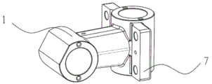
The screw nut seat of the milling machine, also called the screw angle tooth seat of the milling machine or the cross nut seat, is divided into an X direction (shown in figure 1) and a Y direction, which are key parts of the turret milling machine, and relate to the motion states and the precision of the X direction and the Y direction of the machine tool, so that comprehensive detection is required, and a quality control point is established; the detecting content comprises the following steps: the size of the X-direction hole diameter; 2. verticality of the Y-direction hole and the X-direction hole; 3.Y radial runout of the hole and the hole axis; the traditional method generally uses a three-coordinate measuring machine for detection, but the detection cost is high; if the universal measuring tool is adopted for measurement, the workpiece needs to be overturned for many times to finish the detection items of the parts, and the items related to the form and position tolerance cannot be finished.
Disclosure of Invention
In order to solve the technical problems, the utility model provides an X-direction hole detection device for a screw nut seat of a milling machine, which can realize comprehensive detection of the screw nut seat of the milling machine.
The specific technical scheme is as follows: the X-direction hole detection device for the screw rod and nut seat of the milling machine comprises a smooth working table surface, wherein a measuring table support is fixedly arranged on the smooth working table surface, a vertical measuring rod is vertically arranged on the measuring table support and is used for sleeving the nut seat on the measuring table support and detecting the size of the vertical measuring rod; the smooth table surface is movably provided with a push block which is made of steel materials, the bottom surface of the push block is smooth, the push block is provided with a hydraulic magnetic gauge stand, and the end head of the hydraulic magnetic gauge stand is provided with a lever dial indicator. The measuring table support is a circular boss structure, a hole is formed in the base of the circular boss structure, the measuring table support is convenient to connect with a smooth working table surface through a bolt or a screw, a counter bore is formed in the center of the upper end of the circular boss structure, and the vertical measuring rod is convenient to install.
Preferably, the smooth countertop is a 000-grade marble slab.
Preferably, the lower surface roughness of the push block is less than 0.4.
Preferably, the side edge of the smooth working table surface is provided with a suspension ring screw.
The beneficial effects are that: according to the utility model, a precise measuring support is arranged on a 000-grade marble plate, and a vertical measuring rod is vertically arranged on the precise measuring support; the 000-level marble plate is convenient for realizing flexible installation and movement of the hydraulic magnetic gauge stand; through the combined use of various measurement accessories, the milling machine screw nut seat is sleeved on the vertical measurement rod, the transverse measurement rod extends into the transverse hole of the milling machine screw nut seat, and the lever dial indicator on the movable hydraulic magnetic gauge seat is in contact with the transverse measurement rod for measurement. The utility model can detect the precision detection items such as the aperture size of the X-direction hole of the milling machine screw cross nut seat, the perpendicularity of the Y-direction hole and the X-direction, the radial runout of the Y-direction hole and the hole axis, and the like.
Drawings
FIG. 1 is an X-direction view of a milling machine screw nut seat;
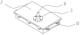
FIG. 2 is a schematic view of a measurement table support;
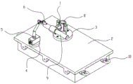
FIG. 3 is a reference view of the usage status of the present utility model;
1, a screw nut seat of a milling machine; 2. a smooth work surface; 3. a measuring table support; 4. a pushing block; 5. a hydraulic magnetic gauge stand; 6. lever dial gauge; 7, wing plates; 8, a vertical measuring rod; 9 measuring the bar transversely; and 10, hanging ring screws.
Description of the embodiments
As shown in figure 1, the X-direction milling machine screw nut seat 1 (abbreviated as nut seat), two sides of the right hole seat in figure 1 are provided with wing plates 7, and the X-direction hole detection device of the milling machine screw nut seat (shown in figure 3) comprises a smooth working table surface 2, preferably a 000-grade marble plate. A measuring table support 3 (shown in fig. 2) is fixedly arranged on the smooth working table surface 2, a vertical measuring rod 8 is vertically arranged on the measuring table support 3, and is used for sleeving a nut seat on the measuring table support 3 and detecting the size of the vertical measuring rod; the smooth working table surface 2 is movably provided with a push block 4 which is made of steel materials, the bottom surface of the push block is smooth, and preferably, the roughness of the lower surface of the push block is less than 0.4; the push block 4 is provided with a hydraulic magnetic gauge stand 5, and the end head of the hydraulic magnetic gauge stand is provided with a lever dial indicator 6. The vertical measuring rod 8 is sleeved with the vertical hole of the milling machine screw nut seat 1, and the transverse measuring rod 9 transversely penetrates through the transverse hole. The side edge of the surface of the smooth workbench 2 is provided with a suspension ring screw 10.
The specific detection mode is as follows: the smooth working table top 2 is arranged on an adjustable base, namely three height-adjustable bolts (the existing mature technology) are arranged at the upper end of the base, and the level of the smooth working table top is adjusted; a measuring table support 3 is fixedly arranged on the smooth working table surface 2 through bolts, and a vertical measuring rod 8 is arranged on the measuring table support 3; the measuring table support 3 is of a circular boss structure, a hole is formed in the base of the circular boss structure, the circular boss structure is convenient to connect with the smooth working table surface 2 through a bolt or a screw, a counter bore is formed in the center of the upper end of the circular boss structure, and the vertical measuring rod 8 is convenient to install; when the vertical hole of the milling machine screw nut seat 1 is sleeved with the vertical measuring rod 8, the transverse measuring rod 9 transversely passes through the transverse hole; the push block 4 and the movable hydraulic magnetic gauge stand 5 are placed on the smooth working table surface 2, the lever dial indicator 6 is arranged on the hydraulic magnetic gauge stand 5, and the movable push block 4 and the movable hydraulic magnetic gauge stand 5 enable the lever dial indicator 6 to be in contact with a measuring rod, so that detection of corresponding items is achieved.
Detection station one:
1. detecting the aperture size phi 40 (0, +0.025) in the Y direction, measuring by adopting a positioning mandrel of a measuring tool support, and flexibly judging whether the aperture size is qualified or not by using a torque wrench to rotate;
2. detecting the cylinder degree of the Y-direction hole of 0.012 and the hole contact precision, measuring by adopting a positioning mandrel of a measuring tool support, coating red lead powder, rotating by using a torque wrench, and taking down the number of the contact points (8-12 points are qualified every 25X25 square millimeters);
3. detecting the perpendicularity and contact precision of the end face of the Y-direction hole and the axis, measuring by adopting the positioning core shoulder face of the measuring tool support, coating red lead powder, rotating by using a torque wrench, and taking down the number of contact points (8-12 points are qualified every 25X25 square millimeters);
4. detecting the length dimension 82+/-0.08 of the Y-direction hole, measuring by adopting the end face of a positioning mandrel of a measuring tool support, measuring the height difference by using a depth gauge, and indirectly measuring and controlling the height difference within +/-0.08;
and a detection station II: (after the station one is completed, the mandrel on the measuring tool support is locked to the Y-direction hole)
1. Detecting the aperture size phi 40 (0, +0.025) of the X direction, and adopting a plug gauge passing end-to-end and end-to-end non-entering mode;
2. detecting the cylinder degree and the hole contact precision of the X-direction hole, measuring by adopting a mode that the mandrel is coated with red lead powder and then penetrates into the X-direction hole, rotating by using a torque wrench, and taking down the number of the contact points (8-12 points are qualified every 25X25 square millimeters);
3. detecting radial runout of the X-direction hole and the axis, measuring by penetrating the mandrel into the X-direction hole, rotating by using a torque wrench, performing metering measurement by using a mandrel busbar, and obtaining a measurement result by looking at the meter reading change and calculating a difference value;
4. detecting the perpendicularity of the X-direction hole and the Y-direction hole to be 0.012, measuring by penetrating the mandrel into the X-direction hole, rotating by using a torque wrench, measuring the maximum value along the axial direction by the movement of a positive bus striking meter on a table surface, and obtaining a measuring result by looking at the reading change of the two ends of the meter along the radial direction to calculate a difference value;
detection station III
1. Detecting the center height of the mounting surface and the X-direction hole, measuring by penetrating the mandrel into the X-direction hole, measuring the distance between the bus of the mandrel and the mounting surface by using a special block gauge (passing end and stopping end), and indirectly measuring the center height.
Combining a screw rod nut seat of a specific milling machine, and measuring the following modes:
1. detecting Y-direction aperture size phi 40 (0, +0.025);
part cleaning, detecting device cleaning, part installation, torque wrench rotation and rotation flexibility degree judgment.
2. Detecting the cylinder degree 0.012 of the Y-direction hole and the hole contact precision;
the Y-direction hole is coated with red lead powder, parts are installed, a torque wrench rotates a grinding point, a point is taken down, and 8-12 points of the internal dyeing point of 25 multiplied by 25 square millimeters are qualified.
3. Detecting the perpendicularity and contact accuracy of the end face of the Y-direction hole and the axle center;
the end face of the Y-direction hole is coated with red lead powder, parts are installed, a torque wrench rotates to grind points, the point is taken down, and 8-12 points of the 25 multiplied by 25 square millimeter internal dyeing points are qualified.
4. Detecting the length dimension 82+/-0.08 of the Y-direction hole;
mounting parts, calibrating a depth gauge, measuring, reading and judging whether the parts are qualified or not
1. Detection of X-ray Aperture dimension phi 40 (0, +0.025)
Part cleaning, plug gauge cleaning, part installation, plug gauge passing end measurement, plug gauge non-stop end measurement and judging whether the part is qualified or not
2. Detecting X-direction hole cylindricity and hole contact precision
The X-direction hole is coated with red lead powder, the core rod is penetrated, the torque wrench rotates to grind the point, the point is taken down, and 8-12 points of the internal dyeing point of 25 multiplied by 25 square millimeters are qualified.
3. Radial runout of X-direction hole and axle center is detected
The method comprises the steps of cleaning a core rod, penetrating the core rod, calibrating a meter, eating the meter, rotating a torque wrench for 3 circles, reading, calculating a difference value and judging whether the product is qualified or not.
4. Detecting the perpendicularity of the X-direction hole and the Y-direction hole to be 0.012
Calibration, one end eating table (highest point), the other end eating table (highest point), reading, calculating difference value and judging whether the product is qualified or not.
5. Detecting the center height of the mounting surface and the X-direction hole
Block gauge cleaning, passing end measurement, end stop measurement and judging whether the block gauge is qualified or not.
Claims (5)
1. The X-direction hole detection device of the milling machine screw nut seat is characterized by comprising a smooth working table surface,
a measuring table support is fixedly arranged on the smooth working table surface, a vertical measuring rod is vertically arranged on the measuring table support, and the measuring table support is used for sleeving a nut seat on the measuring table support and detecting the size of the vertical measuring rod;
the smooth table surface is movably provided with a push block which is made of steel materials, the bottom surface of the push block is smooth, the push block is provided with a hydraulic magnetic gauge stand, and the end head of the hydraulic magnetic gauge stand is provided with a lever dial indicator.
2. The device for detecting the X-direction hole of the screw-nut seat of the milling machine according to claim 1, wherein the measuring table support is a circular boss structure, a hole is formed in the base of the circular boss structure, the circular boss structure is conveniently connected with a smooth working table surface through a bolt or a screw, a counter bore is formed in the center of the upper end of the circular boss structure, and a vertical measuring rod is conveniently installed.
3. The device for detecting the X-direction hole of the screw nut seat of the milling machine according to claim 1, wherein the smooth working table surface is a 000-grade marble plate.
4. The device for detecting the X-direction hole of the screw nut seat of the milling machine according to claim 1, wherein the roughness of the lower surface of the push block is less than 0.4.
5. The device for detecting the X-direction hole of the screw nut seat of the milling machine according to claim 1, wherein the side edge of the smooth working table surface is provided with a lifting screw.
Priority Applications (1)
| Application Number | Priority Date | Filing Date | Title |
|---|---|---|---|
| CN202320092043.1U CN219275318U (en) | 2023-01-31 | 2023-01-31 | X-direction hole detection device for milling machine screw rod nut seat |
Applications Claiming Priority (1)
| Application Number | Priority Date | Filing Date | Title |
|---|---|---|---|
| CN202320092043.1U CN219275318U (en) | 2023-01-31 | 2023-01-31 | X-direction hole detection device for milling machine screw rod nut seat |
Publications (1)
| Publication Number | Publication Date |
|---|---|
| CN219275318U true CN219275318U (en) | 2023-06-30 |
Family
ID=86921910
Family Applications (1)
| Application Number | Title | Priority Date | Filing Date |
|---|---|---|---|
| CN202320092043.1U Active CN219275318U (en) | 2023-01-31 | 2023-01-31 | X-direction hole detection device for milling machine screw rod nut seat |
Country Status (1)
| Country | Link |
|---|---|
| CN (1) | CN219275318U (en) |
-
2023
- 2023-01-31 CN CN202320092043.1U patent/CN219275318U/en active Active
Similar Documents
| Publication | Publication Date | Title |
|---|---|---|
| CN103341789B (en) | Sensor position adjusting device for spindle rotation error detection | |
| CN219275318U (en) | X-direction hole detection device for milling machine screw rod nut seat | |
| CN201104211Y (en) | Universal angle alignment measuring gauge | |
| CN108844444B (en) | Measuring tool and measuring method for perpendicularity and intersection degree of large-scale machine body cylinder hole and main shaft hole | |
| CN208514184U (en) | A kind of polygonal position keyway alignment tool of axis class | |
| CN201266062Y (en) | Apparatus for accurately measuring tooth thickness of rack with irregular curve teeth | |
| CN110270849A (en) | A kind of axis aligning method of pivoting part and the pivoting part | |
| CN219403542U (en) | Y-direction hole detection device for milling machine screw nut seat | |
| CN203732008U (en) | Universal joint external star-wheel ball groove concentricity and system plane height measuring tool | |
| CN215338035U (en) | Cylindricity detection tool for aviation precision thin-wall part | |
| CN212539036U (en) | Large-scale axle class cone tapering measuring device | |
| CN110961701A (en) | Marine base plane on-site milling method | |
| CN212963163U (en) | Detection tool for concentricity of circular arc surface of valve body | |
| CN215064189U (en) | Knife handle detection device | |
| CN209820347U (en) | Axle type part length measuring tool | |
| CN218611762U (en) | Novel rocking arm is bored for belt pulley production and processing | |
| CN217686964U (en) | Deep hole cutter precision measurement detection device | |
| CN211639243U (en) | Machining center precision detection square ruler | |
| CN114937397B (en) | Perpendicularity tolerance detection teaching aid | |
| CN211805177U (en) | Auxiliary tile adjusting tool for grinding roller | |
| CN220583365U (en) | Positioning device of three-coordinate measuring machine | |
| CN219235129U (en) | Welding form and position tolerance alignment tool | |
| CN216461786U (en) | Fixed type rotating nut inner raceway positioner | |
| CN216954350U (en) | Tapered roller angle measuring device | |
| CN211262069U (en) | Thread go-no go gauge detection device |
Legal Events
| Date | Code | Title | Description |
|---|---|---|---|
| GR01 | Patent grant | ||
| GR01 | Patent grant |