CN219212444U - Automatic production line for numerical control turning and finished product detection of shaft parts - Google Patents
Automatic production line for numerical control turning and finished product detection of shaft parts Download PDFInfo
- Publication number
- CN219212444U CN219212444U CN202320795552.0U CN202320795552U CN219212444U CN 219212444 U CN219212444 U CN 219212444U CN 202320795552 U CN202320795552 U CN 202320795552U CN 219212444 U CN219212444 U CN 219212444U
- Authority
- CN
- China
- Prior art keywords
- detection
- numerical control
- workpiece
- air cylinder
- lathe
- Prior art date
- Legal status (The legal status is an assumption and is not a legal conclusion. Google has not performed a legal analysis and makes no representation as to the accuracy of the status listed.)
- Active
Links
Images


Classifications
-
- Y—GENERAL TAGGING OF NEW TECHNOLOGICAL DEVELOPMENTS; GENERAL TAGGING OF CROSS-SECTIONAL TECHNOLOGIES SPANNING OVER SEVERAL SECTIONS OF THE IPC; TECHNICAL SUBJECTS COVERED BY FORMER USPC CROSS-REFERENCE ART COLLECTIONS [XRACs] AND DIGESTS
- Y02—TECHNOLOGIES OR APPLICATIONS FOR MITIGATION OR ADAPTATION AGAINST CLIMATE CHANGE
- Y02P—CLIMATE CHANGE MITIGATION TECHNOLOGIES IN THE PRODUCTION OR PROCESSING OF GOODS
- Y02P90/00—Enabling technologies with a potential contribution to greenhouse gas [GHG] emissions mitigation
- Y02P90/02—Total factory control, e.g. smart factories, flexible manufacturing systems [FMS] or integrated manufacturing systems [IMS]
Abstract
The automatic production line for numerical control turning and finished product detection of shaft parts comprises a numerical control double-ended lathe, a lifting device, a detection device and a material taking device, wherein the lifting device and the detection device are arranged on the same side of the numerical control double-ended lathe; the shaft part machining production line can adapt to the cutting errors of shaft parts, is stable and reliable in production, realizes the full inspection of each workpiece, is adjusted in real time according to the production condition of equipment, and effectively improves the qualification rate of the workpieces.
Description
Technical Field
The utility model relates to an automatic production line for numerical control turning and finished product detection of shaft parts.
Background
The shaft part can be rapidly processed by the numerical control double-end lathe to obtain the required shape at two ends, the shaft part processed by the numerical control double-end lathe needs to be subjected to next detection work, the detection work comprises the size of the outer circles at the two ends of the shaft part and the length detection of the shaft part after being processed, at present, the processing and the detection of a production workshop are basically or stepwise carried out, the processing is completed by the numerical control double-end lathe, the subsequent detection is completed by a detection tool manually, the processing and the detection are not automated, the production process involves more labor force, the efficiency is to be improved, and certain errors exist in the manual detection, so that the homogeneity of the workpiece is poor.
Through searching, the utility model patent application with the publication number of CN113927308A discloses a long shaft type part processing production line, in the scheme, a multi-shaft robot is selected as an upper and lower feeding robot, a double-sided milling special machine, a numerical control lathe, a chip cleaning detection device and a finished product conveying line are all arranged around the upper and lower feeding robot, the upper and lower feeding robot is selected as the multi-shaft robot, the whole cost of the production line is higher, the efficiency of workpiece transfer by the multi-shaft robot is not high, the multi-shaft robot is limited by space, the conventional maintenance, the maintenance and the overhaul of the production line are inconvenient, more workshop area is occupied in a mode of surrounding the upper and lower feeding robot, and the production line is to be further perfected.
Disclosure of Invention
Aiming at the defects existing in the problems, the utility model provides an automatic production line for numerical control turning and finished product detection of shaft parts.
In order to achieve the above purpose, the utility model provides an automatic production line for numerical control turning and finished product detection of shaft parts, which comprises a numerical control double-ended lathe, a lifting device and a detection device which are arranged on the same side of the numerical control double-ended lathe, and a material taking device which is arranged above the numerical control double-ended lathe, wherein the machine head of the numerical control double-ended lathe, a material feeding station of the lifting device and a detection station of the detection device are positioned on the same straight line, and the material taking device is used for grabbing and conveying a blank piece of the lifting device to the machine head of the numerical control double-ended lathe, and simultaneously grabbing and conveying a workpiece machined and molded by the numerical control double-ended lathe to the detection station of the detection device;
the detection device is used for detecting the machined and molded workpiece and distinguishing qualified workpieces from unqualified workpieces, and comprises a detection frame used for placing the machined and molded workpiece, a combined cylinder arranged on the detection frame and used for clamping and positioning the workpiece after being placed, a first detection mechanism arranged on the detection frame and used for detecting the length of the molded workpiece, and a second detection mechanism arranged on the detection frame and used for detecting the outer circle size of the molded workpiece;
the first detection mechanism comprises a fixed measuring head arranged at one end of the detection station and a movable measuring head arranged at the other end of the detection station, the movable measuring head is driven by a fixed first air cylinder, a sensor is fixed on the first air cylinder, a synchronous disc is arranged at the opposite end of the first air cylinder to the movable measuring head, and the synchronous disc abuts against the sensor and then outputs the length of a formed workpiece;
the second detection mechanism comprises a detection module arranged below the detection station and a second air cylinder arranged on the detection module, the detection module is provided with detection chucks which can be elastically clamped on two sides of the formed workpiece, the second air cylinder is connected with the detection chucks and used for enabling the two detection chucks to be far away from each other, and the detection chucks clamp the formed workpiece and then output the outer circle size of the formed workpiece;
the shaft part machining production line can adapt to the cutting errors of shaft parts, is stable and reliable in production, realizes the full inspection of each workpiece, is adjusted in real time according to the production condition of equipment, and effectively improves the qualification rate of the workpieces; the machine head of the numerical control double-end lathe, the feeding station of the lifting device and the detection station of the detection device are arranged in a straight line, so that the material taking device is simplified, the selection of a multi-axis robot is avoided, the cost is reduced, and the material taking device arranged in a straight line can also greatly improve the working efficiency of the whole machine; the whole layout of the production line is compact and reasonable, the occupied area is small, the production cost of enterprises is reduced, and the maintenance, repair and debugging of each device and the operation and debugging of the production line are more convenient.
As a further improvement of the scheme, the lifting device comprises a stock bin, a plurality of fixed plates and movable plates, wherein the fixed plates and the movable plates are arranged at one end of the stock bin at intervals in an inclined manner, and the movable plates are driven by a hinge cylinder to slide relatively along the surface of the fixed plates, so that blanks are gradually fed to the feeding station;
in the technical scheme, the design mode of the fixed plates and the movable plates which are arranged at intervals and in an inclined manner can ensure effective and rapid feeding of shaft parts and ensure the feeding speed of the lifting device.
As a further improvement of the scheme, the material taking device comprises a guide rail which is arranged in a straight line, a sliding block which slides along the guide rail, a first manipulator and a second manipulator which are arranged on the sliding block and can be lifted on a vertical line to grasp or release a workpiece;
in the technical scheme, the first mechanical arm and the second mechanical arm are pneumatic mechanical clamping jaws, so that workpieces can be clamped or released rapidly, and the material taking device is stable in operation.
As a further improvement of the scheme, the whole detection frame is driven by a fixed third cylinder to realize horizontal sliding, a finished product bin, a waste bin and a movable sorting plate are arranged below the detection frame, the sorting plate is driven by a fixed fourth cylinder to realize horizontal sliding, qualified workpieces are guided by the sorting plate and slide into the finished product bin, and unqualified workpieces directly fall into the waste bin;
in the technical scheme, unqualified workpieces can be removed in time through the action of the sorting plate, and meanwhile, the production line can adjust the feed amount of the numerical control double-end lathe in time according to the detected data of the unqualified workpieces, so that automatic compensation is realized.
Compared with the prior art, the utility model has the beneficial effects that: the shaft part machining production line can adapt to the cutting errors of shaft parts, is stable and reliable in production, realizes the full inspection of each workpiece, is adjusted in real time according to the production condition of equipment, and effectively improves the qualification rate of the workpieces; the machine head of the numerical control double-end lathe, the feeding station of the lifting device and the detection station of the detection device are arranged in a straight line, so that the material taking device is simplified, the selection of a multi-axis robot is avoided, the cost is reduced, and the material taking device arranged in a straight line can also greatly improve the working efficiency of the whole machine; the whole layout of the production line is compact and reasonable, the occupied area is small, the production cost of enterprises is reduced, and the maintenance, repair and debugging of each device and the operation and debugging of the production line are more convenient.
Drawings
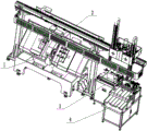
FIG. 1 is a perspective view of an automatic production line for numerical control turning and finished product detection of shaft parts;
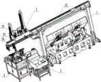
FIG. 2 is a perspective view of an automated production line for numerical control turning and finished product detection of shaft parts according to the present utility model;
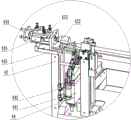
FIG. 3 is a perspective view of the inspection apparatus in the production line;
FIG. 4 is a perspective view of the inspection apparatus in the production line;
FIG. 5 is an enlarged view of the position A of FIG. 3;
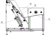
FIG. 6 is a perspective view of a lifting device in the production line;
fig. 7 is a cross-sectional view of a lifting device in the production line.
In the figure: 1. Numerical control double-end lathe; 2. a material taking device; 21. a guide rail; 22. a slide block; 23. a first manipulator; 24. a second manipulator; 3. a lifting device; 31. a storage bin; 32. a fixing plate; 33. a movable plate; 34. a hinge cylinder; 4. a detection device; 41. a detection frame; 42. a combined cylinder; 43. a first detection mechanism; 431. fixing a measuring head; 432. a movable measuring head; 433. a first cylinder; 434. a synchronization disk; 435. a sensor; 44. a second detection mechanism; 441. a detection module; 442. a second cylinder; 443. detecting a chuck; 45. a third cylinder; 5. a fourth cylinder; 6. a waste bin; 7. a sorting plate; 8. and (5) a finished product bin.
Detailed Description
As shown in fig. 1 and 2, the automatic production line for numerical control turning and finished product detection of shaft parts in the embodiment of the utility model comprises a numerical control double-ended lathe 1, a lifting device 3 and a detection device 4 which are arranged on the same side of the numerical control double-ended lathe 1, and a material taking device 2 which is arranged above the numerical control double-ended lathe 1, wherein the machine head of the numerical control double-ended lathe 1, a feeding station of the lifting device 3 and a detection station of the detection device 4 are positioned on the same straight line, the material taking device 2 is used for grabbing and conveying a blank piece of the lifting device 3 to the machine head of the numerical control double-ended lathe 1, and meanwhile, grabbing and conveying a workpiece machined and formed by the numerical control double-ended lathe 1 to the detection station of the detection device 4;
specifically, referring to fig. 3 to 5, the detecting device 4 is used for detecting a machined and formed workpiece and distinguishing a qualified workpiece from an unqualified workpiece, and the detecting device 4 comprises a detecting frame 41 for placing the machined and formed workpiece, a combined air cylinder 42 arranged on the detecting frame 41 and used for clamping and positioning the workpiece after being placed, a first detecting mechanism 43 arranged on the detecting frame 41 and used for detecting the length of the formed workpiece, and a second detecting mechanism 44 arranged on the detecting frame 41 and used for detecting the outer circle size of the formed workpiece; the first detection mechanism 43 comprises a fixed measuring head 431 arranged at one end of the detection station and a movable measuring head 432 arranged at the other end of the detection station, the movable measuring head 432 is driven by a fixed first air cylinder 433, a sensor 435 is fixed on the first air cylinder 433, a synchronous disc 434 is arranged at the opposite end of the first air cylinder 433 to the movable measuring head 432, and the length of a formed workpiece is output after the synchronous disc 434 abuts against the sensor 435; the second detection mechanism 44 comprises a detection module 441 arranged below the detection station and a second air cylinder 442 arranged on the detection module 441, the detection module 441 is provided with detection chucks 443 capable of being elastically clamped on two sides of the formed workpiece, the second air cylinder 442 is connected with the detection chucks 443 and is used for enabling the two detection chucks 443 to be far away, and the detection chucks 443 clamp the formed workpiece and then output the outer circle size of the formed workpiece;
referring to fig. 6 and 7, the lifting device 3 comprises a storage bin 31, a plurality of fixed plates 32 and movable plates 33 which are arranged at one end of the storage bin 31 at intervals and in an inclined manner, and the plurality of movable plates 33 are driven by a hinge air cylinder 34 to slide relatively along the surface of the fixed plates 32, so that blanks are gradually fed to a feeding station, and the effective and rapid feeding of shaft parts can be ensured by adopting the design modes of the fixed plates and the movable plates which are arranged at intervals and in an inclined manner, and the feeding speed of the lifting device is ensured;
referring to fig. 2, the material taking device 2 includes a guide rail 21, a sliding block 22 sliding along the guide rail 21, a first manipulator 23 and a second manipulator 24 which are arranged on the sliding block 22 and can be lifted on a vertical line to grasp or release a workpiece, wherein the first manipulator and the second manipulator are pneumatic mechanical clamping jaws, so that the workpiece can be rapidly clamped or released, and the material taking device works stably;
referring to fig. 3 and 4, the detection frame 41 is integrally driven by a fixed third cylinder 45 to realize horizontal sliding, a finished product bin 8, a waste bin 6 and a movable sorting plate 7 are arranged below the detection frame 41, the sorting plate 7 is driven by a fixed fourth cylinder 5 to realize horizontal sliding, qualified workpieces are guided by the sorting plate 7 and slide into the finished product bin 8, unqualified workpieces directly fall into the waste bin 6, unqualified workpieces can be removed in time through the action of the sorting plate, and meanwhile, the production line timely adjusts the feed amount of the numerical control double-end lathe according to the detected data of the unqualified workpieces to realize automatic compensation.
The shaft part machining production line can adapt to the cutting errors of shaft parts, is stable and reliable in production, realizes the full inspection of each workpiece, is adjusted in real time according to the production condition of equipment, and effectively improves the qualification rate of the workpieces; the machine head of the numerical control double-end lathe, the feeding station of the lifting device and the detection station of the detection device are arranged in a straight line, so that the material taking device is simplified, the selection of a multi-axis robot is avoided, the cost is reduced, and the material taking device arranged in a straight line can also greatly improve the working efficiency of the whole machine; the whole layout of the production line is compact and reasonable, the occupied area is small, the production cost of enterprises is reduced, and the maintenance, repair and debugging of each device and the operation and debugging of the production line are more convenient.
When in specific use, the utility model is described with reference to the drawings for convenient understanding;
when the material taking device 2 moves to the upper parts of the lifting device 3 and the detecting device 4, the first manipulator 23 moves downwards to grab one blank piece of the material loading station (the hinge cylinder 34 moves once to realize the supplement of the blank piece of the material loading station), the second manipulator 24 places the formed workpiece downwards on the detecting station of the detecting device 4, after the detection is finished, if the workpiece is qualified, the second manipulator 24 grabs the qualified workpiece downwards, the third cylinder 45 drives the whole detecting frame 41 to move to one side, the second manipulator 24 releases the qualified workpiece downwards on the sorting plate 7, and the qualified workpiece slides to the position of the finished product bin 8; after the detection is finished, if the workpiece is unqualified, the second manipulator 24 grabs the unqualified workpiece downwards, the third cylinder 45 drives the whole detection frame 41 to move to one side, meanwhile, the fourth cylinder 5 drives the separation plate 7 to move to one side, the second manipulator 24 releases the unqualified workpiece downwards, and the unqualified workpiece slides to the waste bin 8; then, the material taking device 2 moves to the position of the numerical control double-end lathe 1, the second manipulator 24 takes down the newly formed workpiece, the first manipulator 23 places the gripped blank on the machine head of the numerical control double-end lathe 1, the material taking device 2 moves to the position above the lifting device 3 and the detecting device 4 again, and the material taking device 2 moves back and forth at two positions to circulate the actions.
At the detection device, after the workpiece is placed on the detection frame 41, the combined air cylinder 42 acts to pre-position and compress the workpiece, then the first air cylinder 433 acts to enable the workpiece to be abutted between the fixed measuring head 431 and the movable measuring head 432, the synchronous disc 434 which moves synchronously with the movable measuring head 432 is in contact with the sensor 435, and the length value of the detected workpiece is output by the sensor 435;
before the workpiece is placed on the detection frame 41, the second air cylinder 442 drives the detection chucks 443 on two sides to be far away, after the workpiece is placed on the detection frame 41, the second air cylinder 442 resets, the elastic force enables the detection chucks 443 on two sides to be close to and clamped on two sides of the workpiece, and the detection module 441 calculates and outputs the outer circle size of the workpiece.
The above description is only of the preferred embodiments of the present utility model and is not intended to limit the present utility model, but various modifications and variations can be made to the present utility model by those skilled in the art. Any modification, equivalent replacement, improvement, etc. made within the spirit and principle of the present utility model should be included in the protection scope of the present utility model.
Claims (4)
1. An automatic production line for numerical control turning and finished product detection of shaft parts is characterized in that: the automatic feeding device comprises a numerical control double-ended lathe (1), a lifting device (3) and a detection device (4) which are arranged on the same side of the numerical control double-ended lathe (1), and a material taking device (2) which is arranged above the numerical control double-ended lathe (1), wherein a machine head of the numerical control double-ended lathe (1), a feeding station of the lifting device (3) and a detection station of the detection device (4) are positioned on the same straight line, and the material taking device (2) is used for grabbing and conveying a blank piece of the lifting device (3) to the machine head of the numerical control double-ended lathe (1), and meanwhile grabbing and conveying a workpiece machined and formed by the numerical control double-ended lathe (1) to the detection station of the detection device (4);
the detection device (4) is used for detecting a machined and molded workpiece and distinguishing qualified workpieces from unqualified workpieces, the detection device (4) comprises a detection frame (41) used for placing the machined and molded workpiece, a combined air cylinder (42) arranged on the detection frame (41) and used for clamping and positioning the workpiece after being placed, a first detection mechanism (43) arranged on the detection frame (41) and used for detecting the length of the molded workpiece, and a second detection mechanism (44) arranged on the detection frame (41) and used for detecting the outer circle size of the molded workpiece;
the first detection mechanism (43) comprises a fixed measuring head (431) arranged at one end of the detection station and a movable measuring head (432) arranged at the other end of the detection station, the movable measuring head (432) is driven by a fixed first air cylinder (433), a sensor (435) is fixed on the first air cylinder (433), a synchronous disc (434) is arranged at the opposite end of the first air cylinder (433) to the movable measuring head (432), and the synchronous disc (434) abuts against the sensor (435) and then outputs the length of a formed workpiece;
the second detection mechanism (44) comprises a detection module (441) arranged below the detection station and a second air cylinder (442) arranged on the detection module (441), the detection module (441) is provided with detection chucks (443) capable of being elastically clamped on two sides of a formed workpiece, the second air cylinder (442) is connected with the detection chucks (443) to enable the two detection chucks (443) to be far away from each other, and the detection chucks (443) clamp the formed workpiece and then output the outer circle size of the formed workpiece.
2. The automatic production line for numerical control turning and finished product detection of shaft parts according to claim 1, which is characterized in that: the lifting device (3) comprises a storage bin (31), a plurality of fixed plates (32) and movable plates (33) which are arranged at one end of the storage bin (31) in a plurality of intervals and inclined mode, and the movable plates (33) are driven by a hinge air cylinder (34) to slide relatively along the surface of the fixed plates (32) so that blanks are gradually fed to the feeding station.
3. The automatic production line for numerical control turning and finished product detection of shaft parts according to claim 1, which is characterized in that: the material taking device (2) comprises a guide rail (21) which is arranged in a straight line, a sliding block (22) which slides along the guide rail (21), a first manipulator (23) and a second manipulator (24) which are arranged on the sliding block (22) and can be lifted on a vertical line to grasp or release a workpiece.
4. The automatic production line for numerical control turning and finished product detection of shaft parts according to claim 1, which is characterized in that: the detection frame (41) is integrally driven by a fixed third air cylinder (45) to realize horizontal sliding, a finished product bin (8), a waste bin (6) and a movable sorting plate (7) are arranged below the detection frame (41), the sorting plate (7) is driven by a fixed fourth air cylinder (5) to realize horizontal sliding, and qualified workpieces are guided by the sorting plate (7) and slide to the finished product bin (8), and unqualified workpieces directly fall to the waste bin (6).
Priority Applications (1)
| Application Number | Priority Date | Filing Date | Title |
|---|---|---|---|
| CN202320795552.0U CN219212444U (en) | 2023-04-12 | 2023-04-12 | Automatic production line for numerical control turning and finished product detection of shaft parts |
Applications Claiming Priority (1)
| Application Number | Priority Date | Filing Date | Title |
|---|---|---|---|
| CN202320795552.0U CN219212444U (en) | 2023-04-12 | 2023-04-12 | Automatic production line for numerical control turning and finished product detection of shaft parts |
Publications (1)
| Publication Number | Publication Date |
|---|---|
| CN219212444U true CN219212444U (en) | 2023-06-20 |
Family
ID=86734142
Family Applications (1)
| Application Number | Title | Priority Date | Filing Date |
|---|---|---|---|
| CN202320795552.0U Active CN219212444U (en) | 2023-04-12 | 2023-04-12 | Automatic production line for numerical control turning and finished product detection of shaft parts |
Country Status (1)
| Country | Link |
|---|---|
| CN (1) | CN219212444U (en) |
-
2023
- 2023-04-12 CN CN202320795552.0U patent/CN219212444U/en active Active
Similar Documents
| Publication | Publication Date | Title |
|---|---|---|
| US11571774B2 (en) | Intelligent plate parts machining production line combining universal and special equipment | |
| CN107243661B (en) | Drilling device of full-automatic square hole machine for shaft | |
| CN113794083A (en) | Automatic pin inserting equipment for carrier | |
| CN103639709A (en) | Automatic assembly line of reverser | |
| CN104526743A (en) | PCB-V groove cutting device | |
| CN210849361U (en) | Automatic loading and unloading device of machine tool | |
| CN109048450A (en) | A kind of automatic loading unloading device of digital controlled lathe | |
| CN106903515B (en) | Full-automatic three-point stamping equipment for circular tube parts | |
| CN216085670U (en) | Automatic pin inserting equipment for carrier | |
| CN105328500B (en) | It is built-in with automatic loading/unloading mechanism Digit Control Machine Tool and the method for carrying out work-handling | |
| WO2021135762A1 (en) | Workpiece exchange device and method | |
| CN206305771U (en) | A kind of two station Full-automatic drilling bevelers | |
| CN219212444U (en) | Automatic production line for numerical control turning and finished product detection of shaft parts | |
| CN115816486B (en) | Feeding and discharging workstation of electronic saw reconstruction robot | |
| CN208390475U (en) | A kind of rejected product detects separator automatically | |
| CN217728013U (en) | Hold in palm flitch, material conveying mechanism and automatic feeding blanking machine | |
| CN205363406U (en) | It has automatic shedding mechanism digit control machine tool of going up to embed | |
| CN210452060U (en) | Two main shaft double-turret combined machine tool of opposition with work piece detects function | |
| CN111496305A (en) | Overhead efficient five-axis numerical control milling machine | |
| CN215747696U (en) | Quick numerical control drilling and tapping machine tool | |
| CN110977494A (en) | Intelligent RC (resistor-capacitor) manufacturing production line for optical communication precision parts | |
| CN205363407U (en) | Provide digit control machine tool of manipulator for oneself | |
| CN113770442B (en) | Cutting device and cutting method thereof | |
| CN220772135U (en) | Automatic detection device for motor rotor height | |
| CN204505373U (en) | A kind of PCB-V groove cutter sweep |
Legal Events
| Date | Code | Title | Description |
|---|---|---|---|
| GR01 | Patent grant | ||
| GR01 | Patent grant |