CN219189815U - Cutter relief angle plane grinds adds clamping apparatus - Google Patents
Cutter relief angle plane grinds adds clamping apparatus Download PDFInfo
- Publication number
- CN219189815U CN219189815U CN202121344585.0U CN202121344585U CN219189815U CN 219189815 U CN219189815 U CN 219189815U CN 202121344585 U CN202121344585 U CN 202121344585U CN 219189815 U CN219189815 U CN 219189815U
- Authority
- CN
- China
- Prior art keywords
- clamp
- clamping table
- workpiece
- plate
- fixed plate
- Prior art date
- Legal status (The legal status is an assumption and is not a legal conclusion. Google has not performed a legal analysis and makes no representation as to the accuracy of the status listed.)
- Active
Links
Images


Classifications
-
- Y—GENERAL TAGGING OF NEW TECHNOLOGICAL DEVELOPMENTS; GENERAL TAGGING OF CROSS-SECTIONAL TECHNOLOGIES SPANNING OVER SEVERAL SECTIONS OF THE IPC; TECHNICAL SUBJECTS COVERED BY FORMER USPC CROSS-REFERENCE ART COLLECTIONS [XRACs] AND DIGESTS
- Y02—TECHNOLOGIES OR APPLICATIONS FOR MITIGATION OR ADAPTATION AGAINST CLIMATE CHANGE
- Y02P—CLIMATE CHANGE MITIGATION TECHNOLOGIES IN THE PRODUCTION OR PROCESSING OF GOODS
- Y02P70/00—Climate change mitigation technologies in the production process for final industrial or consumer products
- Y02P70/10—Greenhouse gas [GHG] capture, material saving, heat recovery or other energy efficient measures, e.g. motor control, characterised by manufacturing processes, e.g. for rolling metal or metal working
Abstract
A plane grinding clamp for a rear angle of a cutter consists of a clamping table, a baffle plate, a fixed plate and a top clamp; the included angle alpha 1 between the upper plane and the lower plane of the clamping table is the rear angle of the cutter to be processed; respectively connecting the baffle plate and the fixed plate to the clamping table; the baffle plate is provided with a workpiece station, the fixed plate is provided with an operation station, the operation station is provided with a top clamp, and the workpiece is tightly propped by the top clamp. The utility model utilizes the square cutter back angle with higher processing precision of the conventional grinding machine equipment, in the actual use process, as the clamp is split, the bottom of the clamping table can be processed into any angle, the upper fixing plate and the baffle plate can be universal, the equipment and clamp cost is greatly reduced after different cutters are processed, the clamp can be prolonged and widened, the requirement of simultaneously processing a plurality of workpieces is met, the work cost clamping is flexible and convenient, the production efficiency is greatly improved, and the production cost is greatly reduced.
Description
Technical Field
The utility model relates to a flat grinding machining workpiece clamp, in particular to a square cutter back angle flat grinding machining clamp.
Background
The square cutter is one of the main turning cutters at present, a certain angle is required to be machined on the rear cutter surface to be called a cutter relief angle in consideration of actual use and chip removal requirements, so that the phenomenon that when a product contacts the surface of a workpiece on the cutting edge, the lower side of the cutting edge contacts the workpiece to damage a non-machining area of the workpiece is avoided, meanwhile, smooth discharge of turning scraps is facilitated, the possibility that the scraps scratch the workpiece is reduced, the relief angle is generally 3-9 degrees, and different cutters need to be specifically adjusted due to the fact that the workpiece is machined.
The conventional clearance angle machining method is usually used for machining the required angle on the original vertical clearance surface through grinding, so that machining precision can be guaranteed, most machining equipment is a numerical control machine tool or a special grinding machine, most machining modes adopted are piece-by-piece machining, machining efficiency is low, cost is relatively high, and clearance angle precision is difficult to guarantee if common equipment is used for machining.
Disclosure of Invention
The utility model aims to provide a square cutter relief angle plane grinding clamp with higher machining precision by using conventional grinding machine equipment.
The technical scheme of the utility model is as follows:
a plane grinding clamp for a rear angle of a cutter consists of a clamping table, a baffle plate, a fixed plate and a top clamp; the included angle alpha 1 between the upper plane and the lower plane of the clamping table is the rear angle of the cutter to be processed; respectively connecting the baffle plate and the fixed plate to the clamping table; the baffle plate is provided with a workpiece station, the fixed plate is provided with an operation station, the operation station is provided with a top clamp, and the workpiece is tightly propped by the top clamp.
The clamping bench is provided with a plurality of connecting bolt holes, the baffle is connected to the clamping bench through baffle connecting bolts, and the fixing plate is connected to the clamping bench through fixing plate connecting bolts.
The baffle comprises diaphragm and a plurality of riser, is the work piece station between every riser and the diaphragm.
The fixed plate is of a folded line type, a plurality of protruding positions are arranged on the straight plate and are operation stations, each protruding position corresponds to one workpiece station, a top clamp is arranged on each protruding position, and an included angle alpha 2 of the operation stations is 60-120 degrees.
The ejector clamp consists of an ejector rod and an ejector block, wherein the front part of the ejector rod is provided with threads, the ejector rod penetrates through a through hole reserved at the operation station of the fixed plate to be connected with the ejector block in a threaded mode, and a powerful compression spring is arranged between the ejector block and the fixed plate.
The included angle alpha 3 between the connecting surface of the top block and the contact surface of the workpiece is 135 degrees, a round chamfer with the diameter of 0.5-3 mm is arranged at the joint of the two vertical surfaces of the top block, which are in contact with the workpiece, and an elastic cushion layer is arranged on the vertical surfaces.
The included angle alpha 1 of the clamping table is 5 degrees, and the included angle alpha 2 of the operating station is 90 degrees.
Compared with the prior art, the square cutter back angle with higher processing precision of conventional grinding machine equipment is utilized, in the actual use process, as the clamp is split, the bottom of the clamping table can be processed into any angle, the upper fixing plate and the baffle plate can be universal, the equipment and clamp cost for processing different cutters is greatly reduced, the clamp can be prolonged and widened, the requirement for simultaneously processing a plurality of workpieces is met, and the work cost clamping is flexible and convenient, so that the production efficiency is greatly improved, and the production cost is greatly reduced.
Drawings
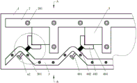
FIG. 1 is a schematic view of the upper surface assembly of the fixture.
FIG. 2 is a cross-sectional view of the clamping table A-A.
Fig. 3 is an enlarged view of a portion of the top clamp.
In the figure: 1 is a clamping table, 101 is a connecting bolt hole, 2 is a baffle, 201 is a baffle connecting bolt, 3 is a fixed plate, 301 is a fixed plate connecting bolt, 302 is a push rod perforation, 4 is a push-clamp, 401 is a push rod, 402 is a powerful compression spring, 403 is a push block, 404 is an elastic cushion, 405 is a round chamfer, and 5 is a workpiece; α1 is the included angle between the upper plane and the lower plane of the clamping table (namely the rear angle of the cutter to be processed), α2 is the included angle of the operating station, and α3 is the included angle between the contact surface of the ejector rod and the contact surface of the workpiece.
Detailed Description
The present utility model is not limited by the following examples, and specific embodiments can be determined according to the technical scheme and practical situations of the present utility model.
For the purpose of making the objects, technical solutions and advantages of the embodiments of the present utility model more apparent, the technical solutions of the embodiments of the present utility model will be clearly and completely described below with reference to the accompanying drawings in the embodiments of the present utility model, and it is apparent that the described embodiments are some embodiments of the present utility model, but not all embodiments. All other embodiments, based on the embodiments of the utility model, which are apparent to those of ordinary skill in the art without inventive faculty, are intended to be within the scope of the utility model.
Thus, the following detailed description of the embodiments of the utility model, which are presented in the drawings, are not intended to limit the scope of the utility model as claimed, but are merely representative of selected embodiments of the utility model, based on which all other embodiments that a person of ordinary skill in the art would achieve without inventive effort are within the scope of the utility model.
It should be noted that: like reference numerals and letters denote like items in the following figures, and thus once an item is defined in one figure, no further definition or explanation thereof is necessary in the following figures.
In the description of the present utility model, it should be understood that the terms "center", "longitudinal", "lateral", "length", "width", "thickness", "upper", "lower", "front", "rear", "left", "right", "vertical", "horizontal", "top", "bottom", "inner", "outer", "clockwise", "counterclockwise", etc. indicate orientations or positional relationships based on the orientations or positional relationships shown in the drawings are merely for convenience in describing the present utility model and simplifying the description, and do not indicate or imply that the apparatus or elements referred to must have a specific orientation, be configured and operated in a specific orientation, and thus should not be construed as limiting the present utility model.
In the present utility model, unless explicitly specified and limited otherwise, the terms "mounted," "connected," "secured," and the like are to be construed broadly, and may be, for example, fixedly connected, detachably connected, or integrally formed; can be directly connected or indirectly connected through an intermediate medium, and can be communicated with the inside of two elements or the interaction relationship of the two elements. The specific meaning of the above terms in the present utility model can be understood by those of ordinary skill in the art according to the specific circumstances.
In the present utility model, unless expressly stated or limited otherwise, a first feature "above" or "below" a second feature may include both the first and second features being in direct contact, as well as the first and second features not being in direct contact but being in contact with each other through additional features therebetween. Moreover, a first feature being "above," "over" and "on" a second feature includes the first feature being directly above and obliquely above the second feature, or simply indicating that the first feature is higher in level than the second feature. The first feature being "under", "below" and "beneath" the second feature includes the first feature being directly under and obliquely below the second feature, or simply means that the first feature is less level than the second feature.
As shown in fig. 1, a tool relief angle plane grinding clamp consists of a clamping table 1, a baffle plate 2, a fixing plate 3 and a top clamp 4, wherein an included angle alpha 1 between an upper plane and a lower plane of the clamping table 1 is the tool relief angle required to be processed. The baffle plate 2 and the fixed plate 3 are respectively connected to the clamping table 1; the baffle 2 is provided with a workpiece station, the fixed plate 3 is provided with an operation station, the operation station is provided with a top clamp 4, and the workpiece 5 is tightly supported by the top clamp 4.
A plurality of connecting bolt holes 101 are formed in the clamping table 1, the baffle plate 2 is connected to the clamping table 1 through baffle plate connecting bolts 201, and the fixing plate 3 is connected to the clamping table 1 through fixing plate connecting bolts 301.
The baffle plate 2 is composed of a transverse plate and a plurality of vertical plates, and a workpiece station is arranged between each vertical plate and the transverse plate. The fixed plate 3 is of a folded line type, namely a plurality of protruding positions are arranged on the straight plate, the protruding positions are operation stations, each protruding position corresponds to one workpiece station, the protruding positions are provided with a top clamp 4, and the workpiece 5 is tightly pressed through the top clamp 4. It should be noted that the included angle α2 of the operation station is 60 to 120 °.
Further, as shown in fig. 3, the top clamp 4 is composed of a top rod 401 and a top block 403, the front part of the top rod 401 is provided with threads, the top rod 401 is connected with the top block 403 in a threaded manner through a through hole reserved at the operation station of the fixed plate 3, and a strong compression spring 402 is installed between the top block 403 and the fixed plate 3.
Further, an included angle alpha 3 between the connecting surface of the top block 403 and the contact surface of the workpiece 5 is 135 degrees, a round chamfer 405 with the diameter of 0.5-3 mm is arranged at the joint of the two vertical surfaces of the top block 403 and the workpiece, and an elastic cushion 404 is arranged on the vertical surfaces, and is made of rubber, nylon and the like.
Preferred embodiments in use are: the included angle alpha 1 of the clamping table 1 is 5 degrees, the included angle alpha 2 of the operation station is 90 degrees, and the diameter of the round chamfer of the top block is phi 1mm. The number of the clamping positions is 5, the top block 403 is pressed outwards, the workpiece is sequentially clamped between the baffle 2 and the top block 403, and the top block 403 is loosened to tightly press the workpiece. And (5) placing the clamp on an electromagnetic plate of a surface grinder, and carrying out normal grinding processing.
The application method of the clamp comprises the following steps:
1) Pressing the top block 403 outwards, and placing a square cutter workpiece 5 to be processed between the top block 403 and the baffle 2;
2) Slowly loosening the top block 403 to the top block to tightly prop up the workpiece 5;
3) After each workpiece is sequentially placed into the clamp according to the method, the clamp is placed on the surface grinder electronic board, and normal grinding can be achieved;
4) The workpiece can be removed by pressing the top block 403 outwards after grinding.
The processed relief angle was measured after processing and compared with 5 pieces of product processed piece by piece using a conventional simple tool grinder, and the specific measurement results are shown in table 1:

TABLE 1
Therefore, the clamp is obviously superior to the existing traditional machining process in machining precision and machining efficiency.
Finally, it should be noted that: the foregoing description is only illustrative of the preferred embodiments of the present utility model, and although the present utility model has been described in detail with reference to the foregoing embodiments, it will be apparent to those skilled in the art that modifications may be made to the embodiments described, or equivalents may be substituted for elements thereof, and any modifications, equivalents, improvements or changes may be made without departing from the spirit and principles of the present utility model.
Claims (7)
1. A cutter relief angle plane grinds adds clamping apparatus which characterized in that: the device consists of a clamping table (1), a baffle (2), a fixed plate (3) and a top clamp (4); the included angle alpha 1 between the upper plane and the lower plane of the clamping table (1) is the rear angle of the cutter to be processed; the baffle plate (2) and the fixed plate (3) are respectively connected to the clamping table (1); the baffle (2) is provided with a workpiece station, the fixed plate (3) is provided with an operation station, the operation station is provided with a top clamp (4), and the workpiece (5) is tightly propped by the top clamp (4).
2. The tool relief angle planar grinding clamp according to claim 1, wherein: a plurality of connecting bolt holes (101) are formed in the clamping table (1), the baffle plate (2) is connected to the clamping table (1) through baffle plate connecting bolts (201), and the fixing plate (3) is connected to the clamping table (1) through fixing plate connecting bolts (301).
3. The tool relief angle planar grinding clamp according to claim 1, wherein: the baffle (2) is composed of a transverse plate and a plurality of vertical plates, and a workpiece station is arranged between each vertical plate and the transverse plate.
4. The tool relief angle planar grinding clamp according to claim 1, wherein: the fixed plate (3) is of a folded line type, a plurality of protruding positions are arranged on the straight plate, the protruding positions are operation stations, each protruding position corresponds to one workpiece station, the protruding positions are provided with a top clamp (4), and an included angle alpha 2 of the operation stations is 60-120 degrees.
5. The tool relief angle planar grinding clamp according to claim 1, wherein: the top clamp (4) is composed of a top rod (401) and a top block (403), threads are arranged at the front part of the top rod (401), the top rod (401) penetrates through a through hole reserved at an operation station of the fixed plate (3) to be connected with the top block (403) in a threaded mode, and a powerful compression spring (402) is arranged between the top block (403) and the fixed plate (3).
6. The tool relief angle planar grinding clamp as set forth in claim 5, wherein: an included angle alpha 3 between the connecting surface of the top block (403) and the contact surface of the workpiece (5) is 135 degrees, a round chamfer angle (405) with the diameter of 0.5-3 mm is arranged at the joint of the two vertical surfaces of the top block (403) and the workpiece, and an elastic cushion layer (404) is arranged on the vertical surfaces.
7. The tool relief angle planar grinding clamp as set forth in claim 4, wherein: the included angle alpha 1 of the clamping table (1) is 5 degrees, and the included angle alpha 2 of the operating station is 90 degrees.
Priority Applications (1)
| Application Number | Priority Date | Filing Date | Title |
|---|---|---|---|
| CN202121344585.0U CN219189815U (en) | 2021-06-17 | 2021-06-17 | Cutter relief angle plane grinds adds clamping apparatus |
Applications Claiming Priority (1)
| Application Number | Priority Date | Filing Date | Title |
|---|---|---|---|
| CN202121344585.0U CN219189815U (en) | 2021-06-17 | 2021-06-17 | Cutter relief angle plane grinds adds clamping apparatus |
Publications (1)
| Publication Number | Publication Date |
|---|---|
| CN219189815U true CN219189815U (en) | 2023-06-16 |
Family
ID=86702098
Family Applications (1)
| Application Number | Title | Priority Date | Filing Date |
|---|---|---|---|
| CN202121344585.0U Active CN219189815U (en) | 2021-06-17 | 2021-06-17 | Cutter relief angle plane grinds adds clamping apparatus |
Country Status (1)
| Country | Link |
|---|---|
| CN (1) | CN219189815U (en) |
-
2021
- 2021-06-17 CN CN202121344585.0U patent/CN219189815U/en active Active
Similar Documents
| Publication | Publication Date | Title |
|---|---|---|
| CN212600493U (en) | Positioning tool for machining bearing seat | |
| CN215316909U (en) | Special drilling and tapping machine for milling end face | |
| CN112191963A (en) | Sheet part machining method | |
| CN219189815U (en) | Cutter relief angle plane grinds adds clamping apparatus | |
| CN212635038U (en) | CNC milling tool for automobile plastic sample piece | |
| CN215147047U (en) | Machine tool platform part clamping is with quick change lathe switching clamp plate mechanism | |
| CN111890256B (en) | Clamping device for bipolar plate and using method thereof | |
| CN210731031U (en) | Novel square quick-change tool rest for lathe | |
| CN209936357U (en) | Large-pressing-plate milling surface drilling clamp | |
| CN218946947U (en) | Milling cylinder plane clamp | |
| CN212735084U (en) | Rapid milling tool utilizing low-position lateral clamping module to be matched with machining center | |
| CN217702482U (en) | Fuselage sheet metal processing frock | |
| CN218110050U (en) | But be used to adjustable flat fixture device that irregularly shaped work piece bored and milled processing | |
| CN220698303U (en) | Frock is used in processing of lead screw bolster bearing frame | |
| CN215545467U (en) | Article corner processing burring cutter | |
| CN210147515U (en) | Clamping tool die for finish machining of machine frame grab handle | |
| CN215280946U (en) | Clamping tool for numerical control machining of medium sample | |
| CN217750469U (en) | Processing tool | |
| CN213164233U (en) | Fixture tool for milling flat pressing plate of grinding machine | |
| CN219704233U (en) | Double-station blade seat milling groove tool | |
| CN213561186U (en) | Buffer device for machining and manufacturing | |
| CN220178668U (en) | Clamping tool for rotary parts | |
| CN204893472U (en) | High symmetry keyway graduation milling fixture | |
| CN218341540U (en) | Frock is used in parts machining with many centre gripping stations | |
| CN216371064U (en) | Energy-saving convenient auxiliary workbench |
Legal Events
| Date | Code | Title | Description |
|---|---|---|---|
| GR01 | Patent grant | ||
| GR01 | Patent grant |