CN219182382U - Sow obstetric table - Google Patents
Sow obstetric table Download PDFInfo
- Publication number
- CN219182382U CN219182382U CN202320204489.9U CN202320204489U CN219182382U CN 219182382 U CN219182382 U CN 219182382U CN 202320204489 U CN202320204489 U CN 202320204489U CN 219182382 U CN219182382 U CN 219182382U
- Authority
- CN
- China
- Prior art keywords
- bottom plate
- bed body
- plate
- bushing
- holes
- Prior art date
- Legal status (The legal status is an assumption and is not a legal conclusion. Google has not performed a legal analysis and makes no representation as to the accuracy of the status listed.)
- Active
Links
Images

Abstract
The utility model discloses a sow obstetric table, which comprises a table body and a spray pipe, wherein a partition plate is arranged in the table body so as to divide the interior of the table body into a sow area and a piglet area, a bottom plate and two bushing plates are arranged at the bottom of the table body, the bottom plate is arc-shaped on the cross section of the bottom plate, and the two bushing plates are obliquely inclined downwards from the center of the bottom plate to two sides, and are respectively connected to two sides of the bottom plate; the shower set up in the top of the bed body, the shower is provided with two, two the shower with the central line symmetry of the bed body sets up, and is located two between the bushing, the shower is provided with a plurality of spray holes, spray hole orientation the central point of bottom plate puts and sets up. The spray pipe sprays towards the central position of the bed body, so that excrement can flow to the bushing plates along with flowing water to the two sides of the bed body, and the excrement at the bottom of the whole bed body is effectively washed.
Description
Technical Field
The utility model relates to the field of breeding equipment, in particular to a sow obstetric table.
Background
In a large-scale pig farm, a pig obstetric table is used, and the pig obstetric table has the main effects of being convenient for managing sows and piglets, providing good sanitary conditions, preventing accumulation of living matters and bacterial reproduction, reducing piglet diseases and improving the survival rate of the piglets. The existing pig obstetric table is provided with a excrement leakage plate or an excrement area, but after the sow and the piglet are excreted, part of excrement remains in the excrement leakage plate and the excrement area, the excrement can not be treated in time, pollution is caused, and diseases are easy to be transmitted.
The utility model patent with the application number of 201721876108.2 discloses a pig obstetric table, including laying the bottom plate on the bottom pillar, setting up sow rail and porkling rail around the bottom plate, the bottom plate includes first bushing plate, porous ceramic plate and the second bushing plate that head and the tail connect gradually, be provided with a plurality of evenly distributed's leak opening on first bushing plate and the second bushing plate, second bushing plate top is provided with the timing rinse-system. In the above-mentioned technical scheme, first bushing and second bushing cooperation timing rinse-system for most excrement can follow and leak away in first bushing and the second bushing, however, is located the excrement at obstetric table middle part often difficult to clear up completely.
Disclosure of Invention
The present utility model aims to solve at least one of the technical problems existing in the prior art. Therefore, the utility model provides a sow obstetric table which can better clean excrement in the obstetric table.
According to the sow obstetric table disclosed by the embodiment of the first aspect of the utility model, the sow obstetric table comprises a table body and a spray pipe, wherein a partition plate is arranged in the table body, so that the interior of the table body is divided into a sow area and a piglet area, the bottom of the table body is provided with a bottom plate and two bushing plates, the bottom plate is arc-shaped on the cross section of the bottom plate, the bottom plate is inclined downwards from the center of the bottom plate to two sides, and the two bushing plates are respectively connected to two sides of the bottom plate; the shower set up in the top of the bed body, the shower is provided with two, two the shower with the central line symmetry of the bed body sets up, and is located two between the bushing, the shower is provided with a plurality of spray holes, spray hole orientation the central point of bottom plate puts and sets up.
The sow obstetric table provided by the embodiment of the utility model has at least the following beneficial effects: the spray pipe sprays towards the central position of the bed body, so that excrement can flow to the bushing plates along with flowing water to the two sides of the bed body, and the excrement at the bottom of the whole bed body is effectively washed.
According to some embodiments of the utility model, the spray holes are provided in plurality, and the spray holes are arranged in equal intervals along the extending direction of the spray pipe.
According to some embodiments of the utility model, two of the spray pipes are attached side by side and are both positioned in a horizontal direction.
According to some embodiments of the utility model, a water tank is arranged at one side of the bed body, the spray pipe is connected with branch pipes, two branch pipes are connected to the same main pipe, the main pipe is connected to the water tank, a water pump is arranged in the water tank, and the water pump is connected with the main pipe.
According to some embodiments of the utility model, the main pipeline is provided with a solenoid valve for controlling the on-off of the main pipeline, and the solenoid valve is electrically connected with a timing controller.
According to some embodiments of the utility model, the bushing plate is provided with a plurality of rows of first holes, the arrangement direction of the first holes in the same row is parallel to the extending direction of the spraying pipe, and the diameter of the first holes close to the bottom plate is smaller than that of the first holes far away from the bottom plate on the cross section of the bushing plate.
According to some embodiments of the utility model, a groove is arranged on one side of the bushing plate away from the bottom plate, and a plurality of second leakage holes are arranged at the bottom of the groove.
According to some embodiments of the utility model, the bottom of the bed body is provided with a manure collecting inclined plate, the tail end of the manure collecting inclined plate is provided with a manure collecting groove, two sides of the manure collecting inclined plate are provided with baffle plates, and the upper edge of the baffle plates are fixedly connected with the bottom of the bed body.
Additional aspects and advantages of the utility model will be set forth in part in the description which follows, and in part will be obvious from the description, or may be learned by practice of the utility model.
Drawings
The utility model is further described with reference to the accompanying drawings and examples, in which:
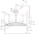
FIG. 1 is a schematic view of a sow obstetric table according to an embodiment of the utility model;
fig. 2 is a schematic view of a shower pipe of a sow obstetric table according to an embodiment of the present utility model.
100. A bed body; 110. a partition plate; 120. a bottom plate; 130. a bushing; 131. a first leak hole; 132. a groove; 1321. a second leak hole; 200. a shower pipe; 210. spraying holes; 220. a branch pipe; 230. a main pipe; 231. an electromagnetic valve; 232. a timing controller; 240. a water tank; 241. a water pump; 300. a manure collecting sloping plate; 310. a manure receiving tank; 320. a baffle;
Detailed Description
Embodiments of the present utility model are described in detail below, examples of which are illustrated in the accompanying drawings, wherein like or similar reference numerals refer to like or similar elements or elements having like or similar functions throughout. The embodiments described below by referring to the drawings are illustrative only and are not to be construed as limiting the utility model.
In the description of the present utility model, it should be understood that references to orientation descriptions such as upper, lower, front, rear, left, right, etc. are based on the orientation or positional relationship shown in the drawings, are merely for convenience of description of the present utility model and to simplify the description, and do not indicate or imply that the apparatus or elements referred to must have a particular orientation, be constructed and operated in a particular orientation, and thus should not be construed as limiting the present utility model.
In the description of the present utility model, a number means one or more, a number means two or more, and greater than, less than, exceeding, etc. are understood to not include the present number, and above, below, within, etc. are understood to include the present number. The description of the first and second is for the purpose of distinguishing between technical features only and should not be construed as indicating or implying relative importance or implicitly indicating the number of technical features indicated or implicitly indicating the precedence of the technical features indicated.
In the description of the present utility model, unless explicitly defined otherwise, terms such as arrangement, installation, connection, etc. should be construed broadly and the specific meaning of the terms in the present utility model can be reasonably determined by a person skilled in the art in combination with the specific contents of the technical scheme.
Referring to fig. 1 and 2, the sow obstetric table of the embodiment of the utility model comprises a table body 100 and a spray pipe 200, wherein a partition plate 110 is arranged in the table body 100, so that the interior of the table body 100 is divided into a sow area and a piglet area, a bottom plate 120 and two drain plates 130 are arranged at the bottom of the table body 100, the bottom plate 120 is arc-shaped on the cross section of the bottom plate 120, and the two drain plates 130 are connected with the two sides of the bottom respectively, and incline downwards from the center of the bottom plate 120 to the two sides; the shower pipes 200 are disposed above the bed body 100, two shower pipes 200 are symmetrically disposed with respect to the center line of the bed body 100 and between the two drain plates 130, and the shower pipes 200 are provided with a plurality of shower holes 210, and the shower holes 210 are disposed toward the center position of the bottom plate 120 as shown by the dotted line in fig. 1.
In the actual use process, the sow is placed in the sow area, the born sow is placed in the sow area, excrement is left in the bed body 100 in the feeding process of the sow and the sow, if the excrement is more, tap water is introduced into the spray pipe 200, the tap water is sprayed out of the spray holes 210, high-pressure tap water is sprayed out towards the central position of the bottom plate 120, the excrement in the middle of the bed body 100 is flushed, so that flowing tap water is continuously arranged in the bed body 100, the flowing tap water starts from the middle of the bed body 100, and flows to the drain plates 130 on two sides of the bottom plate 120 along the inclined two sides (along the arrow direction of fig. 1) with the excrement, and finally the excrement is leaked from the drain plates 130.
In summary, the shower pipe 200 sprays toward the center of the bed body 100, so that excrement can flow into the drain plates 130 along with flowing water toward both sides of the bed body 100, and the excrement at the bottom of the whole bed body 100 can be more effectively washed by utilizing the inclined bottom plate 120 to match with flowing tap water.
In some embodiments, referring to fig. 2, the shower holes 210 are provided in plurality, and the plurality of shower holes 210 are equally spaced along the extension direction of the shower pipe 200. So that the tap water sprayed from the spraying holes 210 can cover the whole area of the bottom plate 120, thereby sufficiently cleaning the excrement in the bed body 100.
Meanwhile, it is preferable that the two shower pipes 200 are attached side by side and are both located in the horizontal direction. The spray position of the spray pipe 200 can be made to cover the entire middle position of the bottom as much as possible.
It should be mentioned that a water tank 240 is disposed at one side of the bed body 100, the shower pipe 200 is connected with branch pipes 220, two branch pipes 220 are connected to a same main pipe 230, the main pipe 230 is connected to the water tank 240, a water pump 241 is disposed in the water tank 240, and the water pump 241 is connected to the main pipe 230. The tap water is pumped 241 to the main pipe 230 by the water pump 241, and is split from the main pipe 230, and finally flows into the two spray pipes 200 from the branch pipe 220, so that tap water is finally sprayed out from the spray holes 210.
Wherein, further, the main pipe 230 is provided with a solenoid valve 231 for controlling the on-off of the main pipe 230, and the solenoid valve 231 is electrically connected with a timing controller 232. The on-off of the electromagnetic valve 231 is controlled by the timing controller 232, so that the spray pipe 200 can automatically clean the bed body 100 at fixed time, too much manual intervention is not needed, and the labor cost is saved.
In some embodiments, the bushing 130 is provided with a plurality of rows of first holes 131, the arrangement direction of the first holes 131 of the same row is parallel to the extending direction of the shower pipe 200, and the diameter of the first holes 131 near the bottom plate 120 is smaller than the diameter of the first holes 131 far from the bottom plate 120 in the cross section of the bushing 130. In the process that excrement is washed out, a large amount of running water can pour into the bed body 100, and part of running water can flow away from the first small-diameter drain hole 131 first, avoids the overflow, and simultaneously the excrement with smaller volume can flow away from the first small-diameter drain hole 131 first, along with running water flowing to one side of the drain plate 130 far away from the bottom plate 120, the excrement with larger volume can flow away along with running water from the first large-diameter drain hole 131 for excrement with different volumes can flow away in batches, avoids too much excrement to pile up in same position, improves the efficiency of clearance.
It should be mentioned that, in order to avoid that too much excrement is accumulated on the side of the bushing 130 away from the bottom plate 120, a groove 132 is provided on the side of the bushing 130 away from the bottom plate 120, a plurality of second holes 1321 are provided at the bottom of the groove 132, and the diameter of the second holes 1321 is larger than that of all the first holes 131. So that the excrement which is not cleaned up is accumulated in the groove 132, and flows away from the second leakage hole 1321, wherein, in order to receive the excrement from the bed body 100, the bottom of the bed body 100 is provided with the excrement receiving sloping plate 300, the tail end of the excrement receiving sloping plate 300 is provided with the excrement receiving groove 310, two sides of the excrement receiving sloping plate 300 are provided with the baffle plates 320, and the upper edge of the baffle plates 320 is fixedly connected with the bottom of the bed body 100. So that the excreta is discharged to the fecal receiving tank 310 and is concentrated.
The embodiments of the present utility model have been described in detail with reference to the accompanying drawings, but the present utility model is not limited to the above embodiments, and various changes can be made within the knowledge of one of ordinary skill in the art without departing from the spirit of the present utility model.
Claims (8)
1. A sow obstetric table comprising:
the bed comprises a bed body (100), wherein a partition plate (110) is arranged in the bed body (100) so that the interior of the bed body (100) is divided into a sow area and a piglet area, a bottom plate (120) and two bushing plates (130) are arranged at the bottom of the bed body (100), the bottom plate (120) is arc-shaped on the cross section of the bottom plate (120), the bottom plate (120) is inclined downwards from the center of the bottom plate (120) to two sides, and the two bushing plates (130) are respectively connected to two sides of the bottom plate (120);
spray pipe (200) set up in the top of the bed body (100), spray pipe (200) are provided with two, two spray pipe (200) with the central line symmetry of the bed body (100) sets up, and is located two between bushing (130), spray pipe (200) are provided with a plurality of spray holes (210), spray hole (210) orientation bottom plate (120) central point puts and sets up.
2. Sow obstetric table according to claim 1, characterized in that said spray holes (210) are provided in a plurality, a plurality of said spray holes (210) being equally arranged along the extension direction of said spray pipe (200).
3. Sow obstetric table according to claim 1, characterized in that two of said shower pipes (200) are attached side by side and are both located in horizontal direction.
4. Sow obstetric table according to claim 1, characterized in that one side of said bed body (100) is provided with a water tank (240), said shower pipe (200) is connected with a branch pipe (220), two said branch pipes (220) are connected to the same main pipe (230), said main pipe (230) is connected to said water tank (240), said water tank (240) is built-in with a water pump (241), said water pump (241) is connected with said main pipe (230).
5. Sow obstetric table according to claim 4, characterized in that said main pipe (230) is provided with a solenoid valve (231) controlling the on-off of said main pipe (230), said solenoid valve (231) being electrically connected with a timing controller (232).
6. Sow obstetric table according to claim 1, characterized in that said bushing plate (130) is provided with a number of rows of first holes (131), the direction of arrangement of the same row of first holes (131) being parallel to the direction of extension of said shower pipe (200), in the cross section of said bushing plate (130) the diameter of said first holes (131) close to said bottom plate (120) being smaller than the diameter of said first holes (131) distant from said bottom plate (120).
7. The sow obstetric table according to claim 6, characterized in that a groove (132) is provided on the side of the bushing plate (130) remote from the bottom plate (120), and a plurality of second leakage holes (1321) are provided at the bottom of the groove (132).
8. The sow obstetric table according to claim 1, characterized in that the bottom of the bed body (100) is provided with a manure collecting inclined plate (300), the tail end of the manure collecting inclined plate (300) is provided with a manure collecting groove (310), two sides of the manure collecting inclined plate (300) are provided with baffle plates (320), and the upper edge of the baffle plates (320) is fixedly connected with the bottom of the bed body (100).
Priority Applications (1)
| Application Number | Priority Date | Filing Date | Title |
|---|---|---|---|
| CN202320204489.9U CN219182382U (en) | 2023-02-10 | 2023-02-10 | Sow obstetric table |
Applications Claiming Priority (1)
| Application Number | Priority Date | Filing Date | Title |
|---|---|---|---|
| CN202320204489.9U CN219182382U (en) | 2023-02-10 | 2023-02-10 | Sow obstetric table |
Publications (1)
| Publication Number | Publication Date |
|---|---|
| CN219182382U true CN219182382U (en) | 2023-06-16 |
Family
ID=86714663
Family Applications (1)
| Application Number | Title | Priority Date | Filing Date |
|---|---|---|---|
| CN202320204489.9U Active CN219182382U (en) | 2023-02-10 | 2023-02-10 | Sow obstetric table |
Country Status (1)
| Country | Link |
|---|---|
| CN (1) | CN219182382U (en) |
-
2023
- 2023-02-10 CN CN202320204489.9U patent/CN219182382U/en active Active
Similar Documents
| Publication | Publication Date | Title |
|---|---|---|
| CN106359139B (en) | Integrated pig raising equipment | |
| CN212138794U (en) | Efficient cleaning pigsty for livestock breeding | |
| CN219182382U (en) | Sow obstetric table | |
| CN208087442U (en) | A kind of energy-saving pig-breeding house | |
| CN217038348U (en) | Sheep is only bred with sheep hurdle excrement and urine cleaning device | |
| CN208480446U (en) | A kind of beef cattle breeding colony house | |
| CN210017429U (en) | Automatic drinking water supply and drainage system for pigs in pig house of live pig farm | |
| CN213074076U (en) | Novel quick blowdown breeding box | |
| CN210987640U (en) | Novel energy-saving blowdown bowl and pig drinking bowl | |
| CN113647339A (en) | Automatically cleaning loop filter milk cow trough | |
| CN208211137U (en) | It is a kind of that worker is facilitated to carry out clean pig house | |
| CN210421304U (en) | Toilet cleaning system | |
| CN208540581U (en) | A kind of Xia Nanniu cowboying automatic water supply device | |
| CN209420604U (en) | A kind of livestock and poultry lavatory of separation of solid and liquid | |
| CN108575766B (en) | Piglet pig house | |
| CN215188702U (en) | Sow obstetric table | |
| CN215012477U (en) | Environment-friendly pig house | |
| CN215302339U (en) | Drinking device for chicken farm | |
| CN212678066U (en) | Be used in belt cleaning device on retaining frame for ox | |
| CN208956636U (en) | A kind of simple sheepfold cleaning blowdown apparatus | |
| CN218473893U (en) | Piglet raises pig house | |
| CN211091223U (en) | Feeding cage | |
| CN215602562U (en) | Automatically cleaning loop filter milk cow trough | |
| CN217958203U (en) | Intelligent environment control device for pigsty | |
| CN216492739U (en) | Poultry is bred cage and uses moisturizing belt cleaning device |
Legal Events
| Date | Code | Title | Description |
|---|---|---|---|
| GR01 | Patent grant | ||
| GR01 | Patent grant |