CN219170428U - Automobile sheet metal polishing device - Google Patents
Automobile sheet metal polishing device Download PDFInfo
- Publication number
- CN219170428U CN219170428U CN202223295107.2U CN202223295107U CN219170428U CN 219170428 U CN219170428 U CN 219170428U CN 202223295107 U CN202223295107 U CN 202223295107U CN 219170428 U CN219170428 U CN 219170428U
- Authority
- CN
- China
- Prior art keywords
- polishing
- subassembly
- assembly
- sheet metal
- frame body
- Prior art date
- Legal status (The legal status is an assumption and is not a legal conclusion. Google has not performed a legal analysis and makes no representation as to the accuracy of the status listed.)
- Active
Links
Images
Classifications
-
- Y—GENERAL TAGGING OF NEW TECHNOLOGICAL DEVELOPMENTS; GENERAL TAGGING OF CROSS-SECTIONAL TECHNOLOGIES SPANNING OVER SEVERAL SECTIONS OF THE IPC; TECHNICAL SUBJECTS COVERED BY FORMER USPC CROSS-REFERENCE ART COLLECTIONS [XRACs] AND DIGESTS
- Y02—TECHNOLOGIES OR APPLICATIONS FOR MITIGATION OR ADAPTATION AGAINST CLIMATE CHANGE
- Y02P—CLIMATE CHANGE MITIGATION TECHNOLOGIES IN THE PRODUCTION OR PROCESSING OF GOODS
- Y02P70/00—Climate change mitigation technologies in the production process for final industrial or consumer products
- Y02P70/10—Greenhouse gas [GHG] capture, material saving, heat recovery or other energy efficient measures, e.g. motor control, characterised by manufacturing processes, e.g. for rolling metal or metal working
Abstract
The application discloses car panel beating grinding device relates to car panel beating processing equipment technical field, the subassembly of polishing, the top at the framework inner chamber is installed to the subassembly of polishing, it includes horizontal translation subassembly, be provided with vertical translation subassembly between horizontal translation subassembly and the framework, the bottom of horizontal translation subassembly is provided with the piece of polishing, spray the subassembly, the subassembly of polishing is installed between polishing and the framework, it includes the water tank, the top of water tank is connected with the inlet tube, the water pump is installed to the interior bottom wall of water tank, the seat is spouted all to the both ends of polishing bottom, be connected with the connecting pipe between two sets of spouting the seat, be connected with the water pipe between right-hand member spouts seat and the water pump. This application sets up through the cooperation of water tank, inlet tube, water pump, spouting seat, connecting pipe and aqueduct to can take out the water in the water tank through the water pump and carry to spouting in the seat through the aqueduct blowout, the piece flies upward when avoiding polishing as far as possible, causes environmental pollution.
Description
Technical Field
The application relates to the technical field of automobile sheet metal machining equipment, in particular to an automobile sheet metal polishing device.
Background
The automobile parts is as the basis of automobile industry, is the essential factor that supports the continuous healthy development of automobile industry, and the accessory of car has a lot, and the panel beating accessory is one of many accessories that automobile production needs, and the panel beating need cut working procedures such as according to the demand before using, can produce influence such as deckle edge after cutting and use, so need polish the panel beating with grinding device.
In the process of realizing the metal plate polishing device, the inventor finds that at least the following problems exist in the technology, the Chinese patent publication No. CN109176228A discloses a metal plate polishing device for automobile production, the device is fixedly connected with a damping spring through the top of a fixed block, the damping effect is achieved, a limiting plate is fixedly connected with the right side of the top of a working platform, the limiting effect is achieved, a clamping block is fixedly connected with the right side of a second electric telescopic rod, the clamping and fixing effects are achieved through the matching of grooves, the problem that the existing polishing device is used for polishing by workers with a polishing machine is solved, the polishing efficiency is low, parts cannot be well fixed, the phenomenon of part movement during polishing often occurs, and the problem of great loss is caused for property of people.
Disclosure of Invention
In order to improve the problem that the device can generate a large amount of scraps when polishing the automobile metal plate, and the scraps can fly upwards to cause environmental pollution if the device is not timely processed, the utility model provides the automobile metal plate polishing device.
The application provides an automobile sheet metal grinding device, adopts following technical scheme:
an automobile sheet metal polishing device comprises a polishing head,
the frame assembly comprises a frame body, and rubber pad feet are connected to four corners of the bottom of the frame body;
the bearing assembly is arranged in the inner cavity of the frame body and comprises two groups of first electric push rods, the two groups of first electric push rods are respectively arranged at two ends of the bottom of the inner cavity of the frame body, a bearing plate is arranged at the top of the two groups of first electric push rods, and clamping pieces are arranged at two ends of the top of the bearing plate;
the polishing assembly is arranged at the top of the inner cavity of the frame body and comprises a transverse translation assembly, a longitudinal translation assembly is arranged between the transverse translation assembly and the frame body, and a polishing piece is arranged at the bottom of the transverse translation assembly;
the polishing device comprises a spraying assembly, wherein the polishing assembly is arranged between a polishing piece and a frame body and comprises a water tank, the top of the water tank is connected with a water inlet pipe, a water pump is arranged on the inner bottom wall of the water tank, two ends of the bottom of the polishing piece are respectively provided with a spraying seat, two groups of spraying seats are connected with connecting pipes, and the right end of each spraying seat is connected with a water guide pipe between the water pump.
Optionally, the both sides of loading board all are connected with the slider, the slide rail has all been seted up to the both sides of framework inner chamber, the slide rail with sliding connection between the slider.
Through adopting above-mentioned technical scheme, can drive the slider and slide in the slide rail when the loading board is removing for the loading board is more steady at the in-process of going up and down.
Optionally, the holder includes two sets of fixed plates, and two sets of the fixed plate is installed respectively the both ends at loading board top, two sets of the fixed plate is close to the one side at loading board center is all installed second electric putter, the grip block is installed to second electric putter's output.
Through adopting above-mentioned technical scheme, second electric putter stretches out and drives the grip block and remove to can adjust the interval between two sets of grip blocks, make the device can carry out the centre gripping to the car panel beating of different specifications, improved the universality of device.
Optionally, two groups of clamping plates are connected with rubber pads on one side close to the center of the bearing plate.
Through adopting above-mentioned technical scheme, increased the frictional force between grip block and the car panel beating through the rubber pad for the car panel beating is held ground more firmly.
Optionally, the polishing piece includes the casing, driving motor is installed to the inner chamber of casing, driving motor's power take off installs the polishing wheel.
Through adopting above-mentioned technical scheme, drive the grinding wheel and rotate when the movable groove starts, conveniently polish the work to the car panel beating.
Optionally, horizontal translation subassembly includes the mount pad, servo motor is installed to the right-hand member of mount pad inner chamber, servo motor's power take off end installs the lead screw, the left end of lead screw with the inner wall of mount pad rotates to be connected, the outer wall threaded connection of lead screw has the screw, the bottom of screw is connected with the connecting rod, the bottom of mount pad seted up with the spacing hole of connecting rod mutual match, the bottom of connecting rod with the top fixed connection of casing.
Through adopting above-mentioned technical scheme, drive the lead screw and rotate when servo motor starts, the lead screw rotates drive screw and removes, and under the spacing effect in spacing hole, the screw drives the piece of polishing through the connecting rod when removing and removes to can adjust the transverse position of piece of polishing.
Optionally, the vertical translation subassembly includes the third electric putter, the third electric putter installs the interior roof of framework, the output of third electric putter with the rear end fixed connection of mount pad, the movable groove has all been seted up to the both sides at frame subassembly inner chamber top, the both ends of mount pad all are connected with the movable block, the movable groove with sliding connection between the movable block.
Through adopting above-mentioned technical scheme, promote the mount pad when the third electric putter stretches out and remove, the mount pad drives movable block and slides in the movable groove to the vertical position of convenient adjustment polishing piece.
Optionally, the interior bottom wall of framework is provided with the waste liquid and collects the subassembly, the waste liquid is collected the subassembly and is included collecting the frame, collect the both ends of frame bottom all be connected with the fixture block, both ends of frame inner chamber bottom all seted up with fixture block grafting complex draw-in groove, collect the width of frame be greater than the width of loading board.
Through adopting above-mentioned technical scheme, can collect the waste water after spraying through collecting the frame, when collecting to a certain amount, upwards lift up and collect the frame for fixture block and draw-in groove separation, thereby can dismantle the collection frame and shift out waste water.
In summary, the present application includes at least one of the following beneficial effects:
(1) Through the cooperation setting of water tank, inlet tube, water pump, spouting seat, connecting pipe and aqueduct to can be taken out the water in the water tank through the water pump and carry to spouting in the seat through the aqueduct, the piece flies upward when avoiding polishing as far as possible, causes environmental pollution.
(2) Through the cooperation setting of fixed plate, second electric putter, grip block and rubber pad, can drive the grip block through the second electric putter is flexible and control and remove, and then can adjust the interval between two sets of grip blocks, make things convenient for the device to carry out the centre gripping to the car panel beating of different specifications, improved the universality of device.
(3) Through horizontal translation subassembly, vertical translation subassembly, the piece of polishing, &, and the cooperation setting to can adjust the horizontal position of the piece of polishing, set up through the cooperation of third electric putter, movable groove and movable block, thereby can adjust the vertical position of the piece of polishing, and then make things convenient for the device to adjust the position of the piece of polishing in a flexible way, polish the work to the different positions of car panel beating, improved the practicality of device.
Drawings
In order to more clearly illustrate the embodiments of the present application or the technical solutions in the prior art, the drawings that are required in the embodiments or the description of the prior art will be briefly described below, it being obvious that the drawings in the following description are only some embodiments of the present application, and that other drawings may be obtained according to these drawings without inventive effort for a person skilled in the art.
FIG. 1 is a schematic cross-sectional view of the present application;
FIG. 2 is a schematic elevational view of the present application;
FIG. 3 is a schematic top view of the carrier plate of the present application;
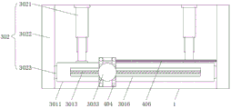
FIG. 4 is a schematic view of a transverse translation member according to the present application
Fig. 5 is a schematic bottom view of the polishing assembly of the present application.
In the figure:
1. a frame assembly; 101. a frame; 1011. a slide rail; 102. rubber pad feet;
2. a carrier assembly; 201. a first electric push rod; 202. a carrying plate; 2021. a slide block; 203. a clamping member; 2031. a fixing plate; 2032. a second electric push rod; 2033. a clamping plate; 20331. a rubber pad;
3. a polishing assembly; 301. a lateral translation member; 3011. a mounting base; 3012. a servo motor; 3013. a screw rod; 3014. a nut; 3015. a connecting rod; 3016. a limiting hole; 302. a longitudinal translation member; 3021. a third electric push rod; 3022. a movable groove; 3023. a movable block; 303. a polishing member; 3031. a housing; 3032. a driving motor; 3033. grinding wheel;
4. a spray assembly; 401. a water tank; 402. a water inlet pipe; 403. a water pump; 404. a spraying seat; 405. a connecting pipe; 406. a water conduit;
5. a waste liquid collection assembly; 501. a collection frame; 502. a clamping block; 503. a clamping groove.
Detailed Description
The utility model is described in further detail below with reference to fig. 1-5.
Embodiment one:
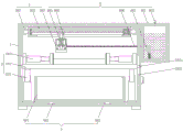
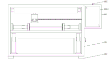
referring to fig. 1 and 2, the utility model discloses an automobile sheet metal polishing device, which comprises a frame assembly 1, wherein the frame assembly comprises a frame body 101, and rubber pad feet 102 are fixedly connected to four corners of the bottom of the frame body 101.
The bearing assembly 2 is arranged in the inner cavity of the frame body 101, the bearing assembly 2 comprises two groups of first electric push rods 201, the two groups of first electric push rods 201 are respectively arranged at two ends of the bottom of the inner cavity of the frame body 101, the top of each group of first electric push rods 201 is provided with a bearing plate 202, and two ends of the top of each bearing plate 202 are respectively provided with clamping pieces 203.
The polishing component 3, the top in the inner chamber of framework 101 is installed to polishing component 3, and it includes horizontal translation subassembly 301, is provided with vertical translation subassembly 302 between horizontal translation subassembly 301 and the framework 101, and the bottom of horizontal translation subassembly 301 is provided with polishing piece 303.
The spraying assembly 4, the polishing assembly 3 is installed between the polishing member 303 and the frame 101, and comprises a water tank 401, and a water inlet pipe 402 is fixedly connected to the top of the water tank 401, so that water can be conveniently added through the water inlet pipe 402. The water pump 403 is installed to the interior bottom wall of water tank 401, and spouts seat 404 is all installed at the both ends of grinding member 303 bottom, and two sets of fixedly connected with connecting pipe 405 between spouting seat 404, and the right-hand member spouts and is connected with water guide pipe 406 between seat 404 and the water pump 403.
Referring to fig. 1, the two sides of the bearing plate 202 are fixedly connected with the sliding blocks 2021, the two sides of the inner cavity of the frame 101 are provided with the sliding rails 1011, the sliding rails 1011 are slidably connected with the sliding blocks 2021, and when the bearing plate 202 moves, the sliding blocks 2021 can be driven to slide in the sliding rails 1011, so that the bearing plate 202 is more stable in the lifting process.
Referring to fig. 1 and 4, the polishing member 303 includes a housing 3031, a driving motor 3032 is fixedly installed in an inner cavity of the housing 3031, a polishing wheel 3033 is installed at a power output end of the driving motor 3032, and the polishing wheel 3033 is driven to rotate when the movable groove 3022 is started, so that polishing work on metal plates of automobiles is facilitated.
Referring to fig. 1 and 2, the inner bottom wall of the frame body 101 is provided with a waste liquid collecting assembly 5, the waste liquid collecting assembly 5 comprises a collecting frame 501, clamping blocks 502 are fixedly connected to two ends of the bottom of the collecting frame 501, clamping grooves 503 which are in plug-in connection with the clamping blocks 502 are formed in two ends of the bottom of the inner cavity of the frame body 101, the width of the collecting frame 501 is larger than that of a bearing plate 202, sprayed waste water can be collected through the collecting frame 501, and when a certain amount of waste water is collected, the collecting frame 501 is lifted upwards, the clamping blocks 502 are separated from the clamping grooves 503, and accordingly the collecting frame 501 can be detached and removed.
The specific implementation principle is as follows: the automobile sheet metal to be polished is placed at the top of the bearing plate 202, the top of the automobile sheet metal is contacted with the bottom of the polishing wheel 3033, at this time, the driving motor 3032 is started, the polishing wheel 3033 is driven to rotate to polish the automobile sheet metal, a large amount of fragments can be generated in the polishing process, the water pump 403 is started at this time, the water pump 403 pumps clean water in the water tank 401 and conveys the clean water into the two groups of spraying seats 404 through the water guide pipe 406 and the connecting pipe 405, the clean water can be sprayed out to prevent the fragments from flying, environmental pollution is avoided as much as possible, sprayed waste water enters the collecting frame 501 to be uniformly collected, when the waste water in the collecting frame 501 is collected to a certain amount, the collecting frame 501 is lifted upwards, and the clamping block 502 is separated from the clamping groove 503, so that the collecting frame 501 can be detached and removed.
Embodiment two:
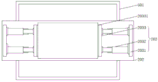
referring to fig. 1 and 3, in this embodiment, based on the same concept as the first embodiment, the clamping member 203 further includes two sets of fixing plates 2031, the two sets of fixing plates 2031 are respectively installed at two ends of the top of the carrier plate 202, one side of the two sets of fixing plates 2031, which is close to the center of the carrier plate 202, is provided with a second electric push rod 2032, an output end of the second electric push rod 2032 is provided with a clamping plate 2033, and the second electric push rod 2032 extends to drive the clamping plate 2033 to move, so that a distance between the two sets of clamping plates 2033 can be adjusted, so that the device can clamp automobile metal plates with different specifications, and universality of the device is improved.
Referring to fig. 3, rubber pads 20331 are fixedly connected to one sides of the two groups of clamping plates 2033, which are close to the center of the bearing plate 202, and friction force between the clamping plates 2033 and the automobile sheet metal is increased through the rubber pads 20331, so that the automobile sheet metal is clamped more firmly.
The specific implementation principle is as follows: after the panel beating is placed at the top of loading board 202, start second electric putter 2032, second electric putter 2032 stretches out and drives clamping plate 2033 and remove towards the direction of car panel beating, until two sets of clamping plates 2033 are fixed the centre gripping with car panel beating, the both ends direct contact of rubber pad 20331 and car panel beating this moment has increased the frictional force between clamping piece 203 and the car panel beating under the effect of rubber pad 20331, and then makes the car panel beating by the centre gripping ground more firm.
Example III
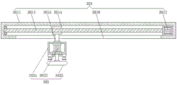
Referring to fig. 4 and 5, in this embodiment, based on the same concept as the first embodiment, the automotive sheet metal polishing device further includes, a transverse translation assembly 301 including a mounting base 3011, a servo motor 3012 is installed at the right end of an inner cavity of the mounting base 3011, a screw rod 3013 is installed at a power output end of the servo motor 3012, a left end of the screw rod 3013 is rotatably connected with an inner wall of the mounting base 3011, a screw nut 3014 is connected with an outer wall thread of the screw rod 3013, a connecting rod 3015 is connected with a bottom of the screw nut 3014, a limiting hole 3016 matched with the connecting rod 3015 is formed in the bottom of the mounting base 3011, the bottom of the connecting rod 3015 is fixedly connected with the top of the housing 3031, the screw rod 3013 is driven to rotate when the servo motor 3012 is started, the screw rod 3013 is driven to move by the connecting rod 3015 under the limiting action of the limiting hole 3016, so that a polishing piece is driven to move by the connecting rod 3015, and a transverse position of the polishing piece 303 can be adjusted.
Referring to fig. 1 and 5, the longitudinal translation assembly 302 includes a third electric push rod 3021, the third electric push rod 3021 is mounted on an inner top wall of the frame body 101, an output end of the third electric push rod 3021 is fixedly connected with a rear end of the mounting base 3011, two sides of an inner cavity top of the frame assembly 1 are provided with movable grooves 3022, two ends of the mounting base 3011 are connected with movable blocks 3023, the movable grooves 3022 are slidably connected with the movable blocks 3023, the mounting base 3011 is pushed to move when the third electric push rod 3021 stretches out, and the mounting base 3011 drives the movable blocks 3023 to slide in the movable grooves 3022, so that the longitudinal position of the polishing piece 303 is conveniently adjusted.
The specific implementation principle is as follows: when the transverse position of the polishing wheel 3033 needs to be adjusted, the servo motor 3012 is started, the servo motor 3012 drives the screw rod 3013 to rotate during working, the screw rod 3013 rotates to drive the screw 3014 to move, under the limiting effect of the limiting hole 3016, the screw 3014 drives the polishing piece 303 below to move under the action of the connecting rod 3015, so that the transverse position of the polishing wheel 3033 is convenient to adjust, when the longitudinal position of the polishing wheel 3033 needs to be adjusted, the third electric push rod 3021 is started, the mounting seat 3011 is pushed to move when the third electric push rod 3021 stretches out, the mounting seat 3011 drives the movable block 3023 to slide in the movable groove 3022, the longitudinal position of the polishing wheel 3033 is convenient to adjust, and the position of the polishing wheel 3033 can be adjusted flexibly, so that the polishing wheel 3033 can polish different positions of automobile metal plates.
The above embodiments are not intended to limit the scope of the present utility model, so: all equivalent changes in structure, shape and principle of the utility model should be covered in the scope of protection of the utility model.
Claims (8)
1. An automobile sheet metal grinding device which is characterized in that: comprising the steps of (a) a step of,
the frame assembly (1) comprises a frame body (101), and rubber pad feet (102) are connected to four corners of the bottom of the frame body (101);
the bearing assembly (2) is arranged in the inner cavity of the frame body (101), the bearing assembly (2) comprises two groups of first electric push rods (201), the two groups of first electric push rods (201) are respectively arranged at two ends of the bottom of the inner cavity of the frame body (101), a bearing plate (202) is arranged at the top of the two groups of first electric push rods (201), and clamping pieces (203) are arranged at two ends of the top of the bearing plate (202);
the polishing assembly (3) is arranged at the top of the inner cavity of the frame body (101), and comprises a transverse translation assembly (301), a longitudinal translation assembly (302) is arranged between the transverse translation assembly (301) and the frame body (101), and a polishing piece (303) is arranged at the bottom of the transverse translation assembly (301);
spray subassembly (4), polishing subassembly (3) are installed polishing piece (303) with between framework (101), it includes water tank (401), the top of water tank (401) is connected with inlet tube (402), water pump (403) are installed to the interior bottom wall of water tank (401), spout seat (404) are all installed at the both ends of polishing piece (303) bottom, two sets of spout and be connected with connecting pipe (405) between seat (404), the right-hand member spout seat (404) with be connected with water pipe (406) between water pump (403).
2. The automotive sheet metal grinding device of claim 1, wherein: both sides of the bearing plate (202) are connected with sliding blocks (2021), both sides of the inner cavity of the frame body (101) are provided with sliding rails (1011), and the sliding rails (1011) are in sliding connection with the sliding blocks (2021).
3. The automotive sheet metal grinding device of claim 1, wherein: the clamping piece (203) comprises two groups of fixing plates (2031), the two groups of fixing plates (2031) are respectively installed at two ends of the top of the bearing plate (202), one side, close to the center of the bearing plate (202), of each fixing plate (2031) is provided with a second electric push rod (2032), and the output end of each second electric push rod (2032) is provided with a clamping plate (2033).
4. A car sheet metal grinding device according to claim 3, characterized in that: one side of each clamping plate (2033) close to the center of the bearing plate (202) is connected with a rubber pad (20331).
5. The automotive sheet metal grinding device of claim 1, wherein: the polishing piece (303) comprises a shell (3031), a driving motor (3032) is installed in an inner cavity of the shell (3031), and a polishing wheel (3033) is installed at a power output end of the driving motor (3032).
6. The automotive sheet metal grinding device of claim 5, wherein: the horizontal translation subassembly (301) is including mount pad (3011), servo motor (3012) are installed to the right-hand member of mount pad (3011) inner chamber, lead screw (3013) are installed to the power take off end of servo motor (3012), the left end of lead screw (3013) with the inner wall rotation of mount pad (3011) is connected, the outer wall threaded connection of lead screw (3013) has screw (3014), the bottom of screw (3014) is connected with connecting rod (3016), the bottom of mount pad (3011) seted up with spacing hole (3016) of connecting rod (3015) mutually supporting, the bottom of connecting rod (3015) with the top fixed connection of casing (3031).
7. The automotive sheet metal grinding device of claim 6, wherein: the vertical translation subassembly (302) includes third electric putter (3021), third electric putter (3021) are installed the interior roof of framework (101), the output of third electric putter (3021) with rear end fixed connection of mount pad (3011), movable groove (3022) have all been seted up to the both sides at frame subassembly (1) inner chamber top, the both ends of mount pad (3011) all are connected with movable block (3023), movable groove (3022) with sliding connection between movable block (3023).
8. The automotive sheet metal grinding device of claim 1, wherein: the waste liquid collecting assembly is characterized in that a waste liquid collecting assembly (5) is arranged on the inner bottom wall of the frame body (101), the waste liquid collecting assembly (5) comprises a collecting frame (501), clamping blocks (502) are connected to two ends of the bottom of the collecting frame (501), clamping grooves (503) which are matched with the clamping blocks (502) in a plugging mode are formed in two ends of the bottom of an inner cavity of the frame body (101), and the width of the collecting frame (501) is larger than that of the bearing plate (202).
Priority Applications (1)
| Application Number | Priority Date | Filing Date | Title |
|---|---|---|---|
| CN202223295107.2U CN219170428U (en) | 2023-04-23 | 2023-04-23 | Automobile sheet metal polishing device |
Applications Claiming Priority (1)
| Application Number | Priority Date | Filing Date | Title |
|---|---|---|---|
| CN202223295107.2U CN219170428U (en) | 2023-04-23 | 2023-04-23 | Automobile sheet metal polishing device |
Publications (1)
| Publication Number | Publication Date |
|---|---|
| CN219170428U true CN219170428U (en) | 2023-06-13 |
Family
ID=86673555
Family Applications (1)
| Application Number | Title | Priority Date | Filing Date |
|---|---|---|---|
| CN202223295107.2U Active CN219170428U (en) | 2023-04-23 | 2023-04-23 | Automobile sheet metal polishing device |
Country Status (1)
| Country | Link |
|---|---|
| CN (1) | CN219170428U (en) |
-
2023
- 2023-04-23 CN CN202223295107.2U patent/CN219170428U/en active Active
Similar Documents
| Publication | Publication Date | Title |
|---|---|---|
| CN111070060A (en) | Special small-size rust cleaning device that polishes of kitchen hardware | |
| CN115446651A (en) | Vertical elevating platform milling machine | |
| CN112388479A (en) | Multifunctional lathe | |
| CN111941254A (en) | Copper part machining device | |
| CN219170428U (en) | Automobile sheet metal polishing device | |
| CN219234762U (en) | Gear machining is with high accuracy cylindrical grinder | |
| CN112605775A (en) | Polishing equipment for machining mechanical parts | |
| CN219380291U (en) | Auxiliary limiting structure for grinding and polishing machine | |
| CN219074867U (en) | Horizontal multi-axis numerical control boring and milling machine | |
| CN219170443U (en) | Grinding tool with cooling structure | |
| CN220408302U (en) | Furniture processing burnishing device | |
| CN218746840U (en) | Glass is burnishing and polishing device for handicraft | |
| CN219275427U (en) | Immersible pump shell grinding device | |
| CN219170570U (en) | Scrap collecting device for cutter machining | |
| CN218110348U (en) | Burnishing machine is used in steel processing with dust absorption function | |
| CN217413429U (en) | Surface treatment device for heavy shifting fork | |
| CN217122745U (en) | Polishing table for machining condensate water recovery pump | |
| CN218427412U (en) | Glass edge grinding machine with cleaning function | |
| CN219805895U (en) | Clamp polishing equipment | |
| CN215470352U (en) | Semi-automatic burnishing device of stainless steel | |
| CN211589677U (en) | Cavity filter surface polishing device | |
| CN220839589U (en) | Shell polishing device for industrial control instrument processing | |
| CN218194458U (en) | Polishing equipment for circuit board metal base plate | |
| CN218517783U (en) | Industrial control automatic bench drill equipment | |
| CN213615952U (en) | Burnishing device is used to casting work piece |
Legal Events
| Date | Code | Title | Description |
|---|---|---|---|
| GR01 | Patent grant | ||
| GR01 | Patent grant |