CN219169321U - Efficient deburring die for hollow cavity of top cover - Google Patents
Efficient deburring die for hollow cavity of top cover Download PDFInfo
- Publication number
- CN219169321U CN219169321U CN202223281046.4U CN202223281046U CN219169321U CN 219169321 U CN219169321 U CN 219169321U CN 202223281046 U CN202223281046 U CN 202223281046U CN 219169321 U CN219169321 U CN 219169321U
- Authority
- CN
- China
- Prior art keywords
- plate
- die
- hollow cavity
- fixedly arranged
- top cover
- Prior art date
- Legal status (The legal status is an assumption and is not a legal conclusion. Google has not performed a legal analysis and makes no representation as to the accuracy of the status listed.)
- Active
Links
Images


Classifications
-
- Y—GENERAL TAGGING OF NEW TECHNOLOGICAL DEVELOPMENTS; GENERAL TAGGING OF CROSS-SECTIONAL TECHNOLOGIES SPANNING OVER SEVERAL SECTIONS OF THE IPC; TECHNICAL SUBJECTS COVERED BY FORMER USPC CROSS-REFERENCE ART COLLECTIONS [XRACs] AND DIGESTS
- Y02—TECHNOLOGIES OR APPLICATIONS FOR MITIGATION OR ADAPTATION AGAINST CLIMATE CHANGE
- Y02E—REDUCTION OF GREENHOUSE GAS [GHG] EMISSIONS, RELATED TO ENERGY GENERATION, TRANSMISSION OR DISTRIBUTION
- Y02E60/00—Enabling technologies; Technologies with a potential or indirect contribution to GHG emissions mitigation
- Y02E60/10—Energy storage using batteries
Landscapes
- Punching Or Piercing (AREA)
Abstract
The utility model discloses a high-efficiency deburring die for a hollow cavity of a top cover, which relates to the technical field of removing burrs in the hollow cavity of the top cover, wherein a female die insert is arranged in a female die plate, a step hole is formed in the female die insert, a top block is arranged in the step hole, a cylindrical table is fixedly arranged on the top surface of the top block, an arc-shaped part distributed around the circumference of the cylindrical table is arranged between the cylindrical table and the top surface of the top block, and the small end part of the top block is in sliding fit with the small hole of the step hole; a vertical spring is arranged in the base, a guide rod is fixedly arranged at the top end of the vertical spring, and the other end of the guide rod upwards penetrates through the lower base plate and is fixedly arranged on the bottom surface of the top block; a guide groove is formed between the limiting plate and the stripper plate, a male die insert is fixedly arranged on the upper base plate, and the lower end part of the male die insert extends into the guide groove. The beneficial effects of the utility model are as follows: compact structure, greatly improved top cap cavity burring efficiency, easy operation.
Description
Technical Field
The utility model relates to the technical field of removing burrs in a hollow cavity of a top cover, in particular to a high-efficiency deburring die for the hollow cavity of the top cover.
Background
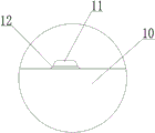
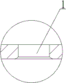
A certain top cover is used for being installed on the battery explosion-proof cover, the structure of the top cover is shown in fig. 1-2, a hollow cavity 1 is formed in the top cover, and the hollow cavity 1 is a circular through hole. The hollow cavity 1 of the top cover is formed by stamping through a progressive die, a large number of burrs 2 are attached to the inner wall of the lower end part of the hollow cavity 1 after forming, and any burrs 2 cannot be arranged in the hollow cavity 1 in the process, so that the hollow cavity 1 can be conveyed to a client. In order to remove burrs 2 in the hollow cavity 1 of each top cover, a polisher is adopted in a workshop to polish the burrs 2 in the hollow cavity 1, wherein a polishing head of the polisher is a cylindrical polishing rod.
The method for removing burrs in the workshop by using the polisher comprises the following steps: the worker firstly adopts a fixture clamp to fix the top cover fixture on the workbench, ensures that the burrs 2 on the top cover face upwards, and then holds the polisher; opening a grinding machine, driving the cylindrical grinding rod to rotate by the grinding machine, then operating the grinding machine by a worker to enable the cylindrical grinding rod on the grinding machine to extend into the hollow cavity 1 from top to bottom, and grinding burrs by the rotating cylindrical grinding rod in the extending process, so that the burrs in a top cover are removed; the repeated operation can be carried out on a batch of top covers for deburring.
However, the use of a polisher in the workshop, while enabling deburring, still has the following technical drawbacks in practical operation: the workman need fix the top cap frock with frock clamp earlier, then in the cylindrical mill stick that the polisher made on it stretches into cavity 1 again, this certainly has increased the burring process, has increased the burring time spent, and then very big reduction the efficiency of top cap burring. Therefore, there is a need for a mold that greatly improves the deburring efficiency of the hollow cavity of the top cover.
Disclosure of Invention
The utility model aims to overcome the defects of the prior art and provides the high-efficiency deburring die for the hollow cavity of the top cover, which has the advantages of compact structure, great improvement on deburring efficiency of the hollow cavity of the top cover and simplicity in operation.
The aim of the utility model is achieved by the following technical scheme: the high-efficiency deburring die comprises an upper die and a lower die, wherein the upper die comprises an upper support, an upper base plate and a fixed plate, wherein the upper base plate and the fixed plate are sequentially fixedly arranged at the bottom of the upper support, a limiting plate and a stripper plate which are fixedly arranged into a whole are arranged below the fixed plate, a gap is reserved between the limiting plate and the fixed plate, and a plurality of vertical springs are fixedly arranged between the limiting plate and the fixed plate; the lower die comprises a base, a lower base plate and a female die plate, wherein the lower base plate and the female die plate are sequentially and fixedly arranged at the top of the base, a female die insert is arranged in the female die plate, a step hole is formed in the female die insert, a jacking block is arranged in the step hole, the big end part of the jacking block is in a step shape and is in sliding fit with the big hole of the step hole, the big end part extends above the female die insert, a cylindrical table is fixedly arranged on the top surface of the jacking block, an arc-shaped part distributed around the circumference of the cylindrical table is arranged between the cylindrical table and the top surface of the jacking block, and the small end part of the jacking block is in sliding fit with the small hole of the step hole;
a vertical spring is arranged in the base, a guide rod is fixedly arranged at the top end of the vertical spring, and the other end of the guide rod upwards penetrates through the lower base plate and is fixedly arranged on the bottom surface of the top block; a guide groove is formed between the limiting plate and the unloading plate, a male die insert is fixedly arranged on the upper base plate, and the lower end part of the male die insert extends into the guide groove.
The diameter of the cylindrical table is smaller than that of the hollow cavity of the top cover.
The male die insert is in sliding fit with the guide groove.
The blind groove is formed in the top surface of the base, the vertical spring is arranged in the blind groove, and the bottom end of the vertical spring is fixedly arranged at the bottom of the blind groove.
And a connector is fixedly arranged on the top surface of the upper support.
The utility model has the following advantages: compact structure, greatly improved top cap cavity burring efficiency, easy operation.
Drawings
FIG. 1 is a schematic view of a top cover;
FIG. 2 is an enlarged schematic view of part I of FIG. 1;
FIG. 3 is a schematic diagram of the structure of the present utility model;
FIG. 4 is a schematic view of the structure of the top block;
FIG. 5 is an enlarged partial schematic view of section II of FIG. 4;
FIG. 6 is a schematic view of the positioning and mounting top cover of the present utility model;
FIG. 7 is an enlarged schematic view of a portion III of FIG. 6;
FIG. 8 is a schematic view of the deburring of the present utility model;
FIG. 9 is an enlarged partial schematic view of section IV of FIG. 8;
FIG. 10 is a schematic view of the finished cap formed;
FIG. 11 is an enlarged partial schematic view of the portion V of FIG. 10;
in the figure, a hollow cavity, 2-burrs, 3-upper brackets, 4-fixing plates, 5-unloading plates, 6-vertical springs, 7-bases, 8-concave templates, 9-concave mold inserts, 10-top blocks, 11-cylinder platforms, 12-arc parts, 13-vertical springs, 14-guide rods, 15-guide grooves, 16-convex mold inserts and 17-top covers.
Detailed Description
The utility model is further described below with reference to the accompanying drawings, the scope of the utility model not being limited to the following:
as shown in fig. 3-5, an efficient deburring die for a hollow cavity of a top cover comprises an upper die and a lower die, wherein the upper die comprises an upper support 3, an upper base plate and a fixed plate 4 which are sequentially fixedly arranged at the bottom of the upper support 3, a connector is fixedly arranged on the top surface of the upper support 3, a limiting plate and a discharging plate 5 which are fixedly arranged into a whole are arranged below the fixed plate 4, a gap is reserved between the limiting plate and the fixed plate 4, and a plurality of vertical springs 6 are fixedly arranged between the limiting plate and the fixed plate 4; the lower die comprises a base 7, a lower base plate and a female die plate 8 which are sequentially and fixedly arranged at the top of the base 7, a female die insert 9 is arranged in the female die plate 8, a step hole is formed in the female die insert 9, a top block 10 is arranged in the step hole, the top block 10 is in a step shape, the large end part of the top block 10 is in sliding fit with the large hole of the step hole, the large end part extends above the female die insert 9, a cylindrical table 11 is fixedly arranged on the top surface of the top block 10, the diameter of the cylindrical table 11 is smaller than the diameter of a hollow cavity 1 of the top cover, an arc-shaped part 12 which is circumferentially distributed around the cylindrical table 11 is arranged between the cylindrical table 11 and the top surface of the top block 10, and the small end part of the top block 10 is in sliding fit with the small hole of the step hole;
as shown in fig. 3 to 5, a vertical spring 13 is disposed in the base 7, a guide rod 14 is fixedly disposed at the top end of the vertical spring 13, and the other end of the guide rod 14 penetrates through the lower pad upward and is fixedly disposed on the bottom surface of the top block 10; a guide groove 15 is formed between the limiting plate and the stripper plate 5, a male die insert 16 is fixedly arranged on the upper base plate, the male die insert 16 is in sliding fit with the guide groove 15, and the lower end part of the male die insert 16 extends into the guide groove 15. A blind groove is formed in the top surface of the base 7, the vertical spring 13 is arranged in the blind groove, and the bottom end of the vertical spring 13 is fixedly arranged at the bottom of the blind groove.
The working process of the utility model is as follows:
s1, fixedly connecting a connector of an upper die on a stamping head of a stamping die;
s2, mounting and positioning the top cover, namely sleeving a hollow cavity 1 of the top cover 17 to be deburred on the cylindrical table 11 by workers, wherein the mounting and positioning of the top cover 17 are realized, the top cover 17 is just under the male die insert 16, and the lower end part of the hollow cavity 1 of the top cover 17 is just supported on the arc-shaped part 12, as shown in fig. 6-7;
s3, removing burrs of the top cover, which specifically comprises the following steps:
s31, a worker controls a stamping head of a stamping die to move downwards, the stamping head drives an upper support 3 to move downwards, the upper support 3 drives an upper base plate, a fixed plate 4, a limiting plate, a stripper plate 5 and a male die insert 16 to move downwards synchronously, and when the die is in a critical die closing state, the stripper plate 5 is just pressed on the top surface of a female die plate 8;
s32, along with the continuous downward movement of the upper support 3, the fixing plate 4 and the male mold insert 16 continuously move downwards relative to the static stripper plate 5, the male mold insert 16 extends out of the lower port of the guide groove 15, the male mold insert 16 presses the top surface of the top cover 17 and pushes the top cover 17 and the top block 10 to synchronously move downwards, in the downward movement process, the top block 10 downwards compresses the vertical spring 13, when the vertical spring 13 is downwards compressed to a certain extent, the vertical spring 13 upwards lifts the top block 10, the top block 10 upwards lifts the cylinder platform 11, the arc-shaped part 12 of the cylinder platform 11 presses the lower end part of the hollow cavity 1, and the arc-shaped part 12 presses burrs at the lower end part of the hollow cavity 1, as shown in figures 8-9;
s33, when the die is in a die-closing state, all burrs 2 at the lower end part of the hollow cavity 1 can be completely removed, so that a finished top cover without burrs is obtained;
s4, after burrs are removed, a worker controls a stamping head of a stamping die to move upwards, the stamping head drives an upper support 3 to move upwards, the upper support 3 drives a fixing plate 4, an upper base plate, a limiting plate, a stripper plate 5 and a male die insert 16 to move upwards synchronously, when the upper die is reset, a vertical spring 13 drives a top block 10 to move upwards, the top block 10 drives a finished top cover to move upwards, and after complete reset, the worker takes away the finished top cover, and the obtained finished top cover has a structure shown in figures 10-11;
s5, repeating the operations of the steps S2-S4, so that burrs at the hollow cavity 1 in the top cover 17 can be continuously removed.
Therefore, in the deburring process of the step S3, only the worker is required to sleeve the hollow cavity 1 of the top cover 17 to be deburred on the cylindrical table 11, then the upper die is controlled to move downwards, so that the arc-shaped part 12 of the cylindrical table 11 can extrude all burrs 2 at the hollow cavity 1 outwards, and the burrs 2 in the hollow cavity 1 are rapidly removed.
Finally, it should be noted that: the foregoing description is only a preferred embodiment of the present utility model, and the present utility model is not limited thereto, but it is to be understood that modifications and equivalents of some of the technical features described in the foregoing embodiments may be made by those skilled in the art, although the present utility model has been described in detail with reference to the foregoing embodiments. Any modification, equivalent replacement, improvement, etc. made within the spirit and principle of the present utility model should be included in the protection scope of the present utility model.
Claims (5)
1. The utility model provides a high-efficient burring mould of top cap cavity, it includes mould and lower mould, and the mould includes upper bracket (3), sets firmly upper padding plate and fixed plate (4) in proper order in upper bracket (3) bottom, and the below of fixed plate (4) is provided with and sets firmly in integrative limiting plate and stripper (5), leaves the clearance between limiting plate and the fixed plate (4), and sets firmly many vertical springs (6) between limiting plate and the fixed plate (4); the lower die comprises a base (7), and a lower base plate and a female die plate (8) which are sequentially fixedly arranged at the top of the base (7), and is characterized in that:
a die insert (9) is arranged in the die plate (8), a step hole is formed in the die insert (9), a jacking block (10) is arranged in the step hole, the jacking block (10) is in a step shape, the large end part of the jacking block (10) is in sliding fit with the large hole of the step hole, the large end part extends above the die insert (9), a cylinder table (11) is fixedly arranged on the top surface of the jacking block (10), an arc-shaped part (12) distributed around the circumference of the cylinder table (11) is arranged between the cylinder table (11) and the top surface of the jacking block (10), and the small end part of the jacking block (10) is in sliding fit with the small hole of the step hole;
a vertical spring (13) is arranged in the base (7), a guide rod (14) is fixedly arranged at the top end part of the vertical spring (13), and the other end of the guide rod (14) upwards penetrates through the lower base plate and is fixedly arranged on the bottom surface of the top block (10); a guide groove (15) is formed between the limiting plate and the unloading plate (5), a male die insert (16) is fixedly arranged on the upper base plate, and the lower end part of the male die insert (16) extends into the guide groove (15).
2. The efficient deburring die for a hollow cavity of a top cover of claim 1, wherein: the diameter of the cylindrical table (11) is smaller than the diameter of the hollow cavity (1) of the top cover.
3. The efficient deburring die for a hollow cavity of a top cover of claim 1, wherein: the male die insert (16) is in sliding fit with the guide groove (15).
4. The efficient deburring die for a hollow cavity of a top cover of claim 1, wherein: a blind groove is formed in the top surface of the base (7), the vertical spring (13) is arranged in the blind groove, and the bottom end of the vertical spring (13) is fixedly arranged at the bottom of the blind groove.
5. The efficient deburring die for a hollow cavity of a top cover of claim 1, wherein: the top surface of the upper support (3) is fixedly provided with a connector.
Priority Applications (1)
| Application Number | Priority Date | Filing Date | Title |
|---|---|---|---|
| CN202223281046.4U CN219169321U (en) | 2022-12-08 | 2022-12-08 | Efficient deburring die for hollow cavity of top cover |
Applications Claiming Priority (1)
| Application Number | Priority Date | Filing Date | Title |
|---|---|---|---|
| CN202223281046.4U CN219169321U (en) | 2022-12-08 | 2022-12-08 | Efficient deburring die for hollow cavity of top cover |
Publications (1)
| Publication Number | Publication Date |
|---|---|
| CN219169321U true CN219169321U (en) | 2023-06-13 |
Family
ID=86672033
Family Applications (1)
| Application Number | Title | Priority Date | Filing Date |
|---|---|---|---|
| CN202223281046.4U Active CN219169321U (en) | 2022-12-08 | 2022-12-08 | Efficient deburring die for hollow cavity of top cover |
Country Status (1)
| Country | Link |
|---|---|
| CN (1) | CN219169321U (en) |
-
2022
- 2022-12-08 CN CN202223281046.4U patent/CN219169321U/en active Active
Similar Documents
| Publication | Publication Date | Title |
|---|---|---|
| CN209754505U (en) | Automatic clamp spring and oil injection assembly machine | |
| CN112276258A (en) | Workpiece clamp on gear scraping machine | |
| CN111618186A (en) | Rapid stamping device for machining automobile parts and using method thereof | |
| CN114769413B (en) | Trimming, positioning and flash removing device for straight forging piece | |
| CN219169321U (en) | Efficient deburring die for hollow cavity of top cover | |
| CN214107964U (en) | Casting mold cleaning device capable of guaranteeing cleaning quality | |
| CN209614869U (en) | A kind of part end face Multi-station synchronous processing tool | |
| CN208245674U (en) | A kind of fixed device of stamping die processing | |
| CN214720193U (en) | Flaring device of stator copper wire | |
| CN210450564U (en) | Numerical control stamping die of circular cylinder | |
| CN210254991U (en) | Lid pressure equipment mechanism behind motor | |
| CN113857823A (en) | Numerical control press-fitting machine tool with self-supporting bearing seat mechanism | |
| CN201618785U (en) | Radially-distributed multi-hole punch | |
| CN114290030B (en) | Assembly device and method for compressor | |
| CN109570383B (en) | Equipment and method for machining annular groove on inner side of annular piece | |
| CN217393436U (en) | Conical gasket stamping forming die | |
| CN218593764U (en) | Pressing die for low-loss magnetic core | |
| CN220560915U (en) | Clamping mechanism of part | |
| CN218656482U (en) | Stator plastic pressure equipment mould | |
| CN217529261U (en) | Efficient tensioning and positioning fixing clamp for machining circular hole workpiece | |
| CN109317592A (en) | A kind of forging and forming device and forming method | |
| CN216800741U (en) | Reduce powder metallurgy mould of angle modulation spare part defective rate | |
| CN218192333U (en) | Spring prepressing machine | |
| CN209050007U (en) | Support base assembles equipment | |
| CN217942845U (en) | Cast aluminium end cover burr clearing device |
Legal Events
| Date | Code | Title | Description |
|---|---|---|---|
| GR01 | Patent grant | ||
| GR01 | Patent grant |