CN210450564U - Numerical control stamping die of circular cylinder - Google Patents
Numerical control stamping die of circular cylinder Download PDFInfo
- Publication number
- CN210450564U CN210450564U CN201921365392.6U CN201921365392U CN210450564U CN 210450564 U CN210450564 U CN 210450564U CN 201921365392 U CN201921365392 U CN 201921365392U CN 210450564 U CN210450564 U CN 210450564U
- Authority
- CN
- China
- Prior art keywords
- die
- stretching
- plate
- mould
- shaping
- Prior art date
- Legal status (The legal status is an assumption and is not a legal conclusion. Google has not performed a legal analysis and makes no representation as to the accuracy of the status listed.)
- Active
Links
Images


Abstract
The utility model discloses a numerical control stamping die of a circular section of thick bamboo, the shaping stamping die of installation and the tensile mould of installation between shaping stamping die side upper die fixing plate and the lower die fixing plate on the lower die fixing plate, the lower die fixing plate that set up including the top, the bottom set up and the shaping stamping die of installation on upper die fixing plate and the lower die fixing plate, shaping stamping die comprises the shaping upper die structure of installation below the upper die fixing plate and the shaping lower die structure of installation on the relative lower die fixing plate of mould structure on the shaping. This numerical control stamping die of circular cylinder adopts and to combine forming die and tensile mould together, carries out synchronous drive through a set of lathe, can carry out the synchronous processing of different technologies to the work piece that does not use, integrates the technology on a set of machine, can effectual reduction mechanical investment cost to the work efficiency of single machinery of effectual improvement.
Description
Technical Field
The utility model relates to the technical field of mechanical equipment, specifically be a numerical control stamping die of a circular cylinder.
Background
The stamping die is a special process device for processing materials into parts in cold stamping processing, and is called as a cold stamping die; punching press, at room temperature, utilize the mould of installing on the press to exert pressure to the material, make it produce separation or plastic deformation, thereby obtain the pressure processing method of required part, numerical control stamping die just uses stamping die cooperation lathe, further improve work efficiency, at the in-process of carrying out circular cylinder stamping process, need the primary forming of circular cylinder, later stretch, after stretching, the side can form the burr, adopt the machine of polishing or burr removal machinery and then secondary punching press, the process is loaded down with trivial details, and consume a large amount of process time, work efficiency is low.
SUMMERY OF THE UTILITY MODEL
An object of the utility model is to provide a numerical control stamping die of a circular cylinder to the in-process that carries out circular cylinder stamping process that proposes in solving above-mentioned background art needs the primary forming of a circular cylinder, later stretches, and after tensile, the side can form the burr, adopts the machine of polishing or deburring machinery and then secondary punching press, and the process is loaded down with trivial details, and consumes a large amount of process time, problem that work efficiency is low.
In order to achieve the above object, the utility model provides a following technical scheme: a numerical control stamping die of a round barrel comprises an upper die fixing plate arranged at the top, a lower die fixing plate arranged at the bottom, a forming stamping die arranged on the upper die fixing plate and the lower die fixing plate, and a stretching die arranged between the upper die fixing plate and the lower die fixing plate on the side of the forming stamping die, wherein the forming stamping die comprises a forming upper die structure arranged below the upper die fixing plate and a forming lower die structure arranged on the lower die fixing plate opposite to the forming upper die structure, and the stretching die comprises a stretching upper die structure arranged on the upper die fixing plate on the side of the forming upper die structure and a stretching lower die structure arranged on the lower die fixing plate on the side of the forming lower die structure; the processing plate is placed on the forming lower die structure and the stretching lower die structure.
Preferably, the mould structure is gone up in the shaping includes mould mounting panel, shaping upper die backing plate, shaping upper die baffle and shaping cope match-plate pattern in the shaping that from the top down set gradually, and mould structure internally mounted has the shaping jumper bar in the shaping to install the jumper bar cover on the shaping cope match-plate pattern in the shaping jumper bar outside, mould structure is driven with the shaping and drives actuating cylinder and be connected in the shaping simultaneously, and the shaping drives actuating cylinder and passes through the roof and install on the punch plate.
Preferably, the shaping of structural installation of mould drives actuating cylinder front end and mould baffle on the shaping and is connected, and the shaping drives and is fixed with spacing supporting pad on the mould baffle on the shaping of actuating cylinder side, and the limiting plate setting of spacing supporting pad upper end mould backing plate top in the shaping, spacing supporting pad passes mould backing plate slidable on the shaping, simultaneously there is spacing supporting pad through the bolt fastening on the mould baffle on the drawing, and the limiting plate setting of spacing supporting pad upper end setting is in mould mounting panel top on the drawing, and the spacing supporting pad of installation passes mould mounting panel slidable on the drawing mould baffle.
Preferably, the lower molding die structure comprises a lower molding die plate and a lower molding die mounting plate which are sequentially arranged from top to bottom, a molding die sleeve is arranged inside the lower molding die plate, a molding core rod capable of sliding up and down is arranged inside the molding die sleeve, and the bottom of a molding core rod spring connected with the lower end of the molding core rod is fixed on the lower molding die structure.
Preferably, the lower stretching die structure comprises a lower stretching die mounting plate, a lower stretching die base plate fixed above the lower stretching die mounting plate and a lower stretching die plate fixed above the lower stretching die base plate, two groups of workpiece supporting sleeves are mounted on the lower stretching die plate, a supporting core rod capable of sliding up and down is mounted inside each workpiece supporting sleeve, and the bottom of a damping spring connected below each supporting core rod is fixed on the lower stretching die mounting plate.
Preferably, the tensile mould structure of going up includes tensile mould mounting panel, the tensile mould baffle of going up that the interval set up in tensile mould mounting panel below, the tensile upper die plate of installation on the tensile mould backing plate of the tensile mould backing plate below fixed mould backing plate of going up of tensile mould, and tensile mould structure is inside to be fixed with tensile pole, and tensile pole bottom is fixed on tensile mould baffle, and slidable tensile pole outer tube has been put to the cover in the tensile mould structure outside, and the tensile mould structure of going up of tensile pole side is fixed with the burring die rod, and the burring die rod bottom is fixed on tensile mould baffle.
Preferably, the upper end of an outer sleeve of a stretching rod mounted on the upper stretching die structure is connected with a push rod, the push rod penetrates through a stretching upper die base plate and a stretching upper die partition plate to be connected with a push rod supporting spring arranged inside an upper die fixing plate, the lower end of the push rod supporting spring penetrates through a stretching upper die mounting plate, and meanwhile two groups of workpiece supporting sleeves arranged on the lower stretching die structure correspond to the stretching rod and deburring punch rod structure arranged on the upper stretching upper die structure.
Preferably, a stretching driving cylinder is mounted on an upper die fixing plate at the upper end of the stretching upper die structure through a top plate, and a telescopic rod at the lower end of the stretching driving cylinder is connected with a stretching upper die base plate arranged on the stretching upper die structure.
Compared with the prior art, the beneficial effects of the utility model are that: this numerical control stamping die of circular cylinder adopts and to put forming die and tensile mould together, carries out synchronous drive through a set of lathe, can carry out the synchronous processing of different technologies to the work piece that does not, integrates the technology on a set of machine, can effectual reduction machinery investment cost to the work efficiency of single machinery of effectual improvement, and set up the burring jumper bar at tensile mould and can carry out further processing to the burr of fashioned work piece side, improve the work piece quality, work efficiency is higher.
Drawings
FIG. 1 is a schematic view of the structure of the present invention showing the upper and lower molds separated;
FIG. 2 is a schematic view of the structure of the present invention showing the closing of the upper and lower molds;
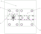
FIG. 3 is a schematic view of the placement of the structural processing plate of the present invention;
fig. 4 is a schematic structural view of the workpiece processed by the structure of the present invention.
In the figure: 1. an upper die fixing plate; 11. a top plate; 12. forming a driving cylinder; 13. stretching the driving cylinder; 2. forming an upper die structure; 21. a limit supporting pad; 22. forming a punch; 23. a plunger sleeve; 24. forming an upper die mounting plate; 25. forming an upper die base plate; 26. forming an upper die clapboard; 27. forming an upper template; 3. forming a lower die structure; 31. forming a female die sleeve; 32. molding a core rod spring; 33. molding a core rod; 34. forming a lower template; 35. forming a lower die mounting plate; 4. a lower die fixing plate; 5. stretching the lower die structure; 51. a workpiece support sleeve; 52. a damping spring; 53. supporting the core rod; 54. stretching the lower die mounting plate; 55. stretching the lower die base plate; 56. stretching the lower template; 6. processing a plate; 7. stretching the upper die structure; 71. a stretch rod outer sleeve; 72. deburring a punch; 73. a stretch rod; 74. a push rod; 75. the push rod supports the spring; 76. stretching the upper template; 77. stretching the upper die base plate; 78. stretching the upper die partition plate; 79. and stretching the upper die mounting plate.
Detailed Description
The technical solutions in the embodiments of the present invention will be described clearly and completely with reference to the accompanying drawings in the embodiments of the present invention, and it is obvious that the described embodiments are only some embodiments of the present invention, not all embodiments. Based on the embodiments in the present invention, all other embodiments obtained by a person skilled in the art without creative work belong to the protection scope of the present invention.
Referring to fig. 1-4, the present invention provides a technical solution: a numerical control stamping die of a round cylinder comprises an upper die fixing plate 1 arranged at the top, a lower die fixing plate 4 arranged at the bottom, a forming stamping die arranged on the upper die fixing plate 1 and the lower die fixing plate 4, and a stretching die arranged between the upper die fixing plate 1 and the lower die fixing plate 4 on the side surface of the forming stamping die, wherein the forming stamping die comprises a forming upper die structure 2 arranged below the upper die fixing plate 1 and a forming lower die structure 3 arranged on the lower die fixing plate 4 opposite to the forming upper die structure 2, the forming lower die structure 3 comprises a forming lower die plate 34 and a forming lower die mounting plate 35 which are sequentially arranged from top to bottom, a forming concave die sleeve 31 is arranged inside the forming lower die plate 34, a forming core bar 33 capable of sliding up and down is arranged inside the forming concave die sleeve 31, the bottom of a forming core bar spring 32 connected with the lower end of the forming, the drawing die consists of a drawing upper die structure 7 arranged on an upper die fixing plate 1 on the side surface of the forming upper die structure 2 and a drawing lower die structure 5 which is arranged on a lower die fixing plate 4 on the side surface of the forming lower die structure 3 and is opposite to the drawing upper die structure 7; the lower stretching die structure 5 comprises a lower stretching die mounting plate 54, a lower stretching die cushion plate 55 fixed above the lower stretching die mounting plate 54 and a lower stretching die plate 56 fixed above the lower stretching die cushion plate 55, two groups of workpiece support sleeves 51 are mounted on the lower stretching die plate 56, a support core rod 53 capable of sliding up and down is mounted inside each workpiece support sleeve 51, the bottom of a damping spring 52 connected below each support core rod 53 is fixed on the lower stretching die mounting plate 54, and the processing plate 6 is placed on the lower forming die structure 3 and the lower stretching die structure 5.
The upper forming die structure 2 comprises an upper forming die mounting plate 24, an upper forming die backing plate 25, an upper forming die partition plate 26 and an upper forming die plate 27 which are sequentially arranged from top to bottom, a forming punch rod 22 is arranged inside the upper forming die structure 2, a punch rod sleeve 23 is arranged on the upper forming die plate 27 outside the forming punch rod 22, the upper forming die structure 2 is connected with a forming driving cylinder 12, the forming driving cylinder 12 is arranged on the upper die fixing plate 1 through a top plate 11, the front end of the forming driving cylinder 12 arranged on the upper forming die structure 2 is connected with the upper forming die partition plate 26, a limiting supporting pad 21 is fixed on the upper forming die partition plate 26 on the side surface of the forming driving cylinder 12, a limiting plate at the upper end of the limiting supporting pad 21 is arranged above the upper forming die backing plate 25, the limiting pad 21 can slide after penetrating through the upper forming die backing plate 25, and the limiting supporting, and the limiting plate setting that the upper end of spacing supporting pad 21 set up is in tensile upper die mounting plate 79 top to the spacing supporting pad 21 of installation passes tensile upper die mounting plate 79 slidable on tensile mould baffle 78.
The upper stretching die structure 7 comprises an upper stretching die mounting plate 79, upper stretching die partition plates 78 arranged below the upper stretching die mounting plate 79 at intervals, an upper stretching die cushion plate 77 fixed below the upper stretching die partition plate 78 and an upper stretching die plate 76 arranged on the upper stretching die cushion plate 77, a stretching rod 73 is fixed inside the upper stretching die structure 7, the bottom of the stretching rod 73 is fixed on the upper stretching die partition plate 78, a slidable stretching rod outer sleeve 71 is sleeved outside the upper stretching die structure 7, a deburring punch 72 is fixed on the upper stretching die structure 7 on the side surface of the stretching rod 73, the bottom of the deburring punch 72 is fixed on the upper stretching die partition plate 78, the upper end of the stretching rod outer sleeve 71 arranged on the upper stretching die structure 7 is connected with a push rod 74, the push rod 74 penetrates through the upper stretching die cushion plate 77 and the upper stretching die plate 78 to be connected with a push rod supporting spring 75 arranged inside the upper die fixing plate, meanwhile, two groups of workpiece supporting sleeves 51 arranged on the lower stretching die structure 5 correspond to the stretching rods 73 and the deburring punch rods 72 arranged on the upper stretching die structure 7 in structural positions, a stretching driving cylinder 13 is mounted on the upper die fixing plate 1 at the upper end of the upper stretching die structure 7 through a top plate 11, and a telescopic rod at the lower end of the stretching driving cylinder 13 is connected with a stretching upper die backing plate 77 arranged on the upper stretching die structure 7.
Installing a die on a numerical control stamping machine tool, placing a processing plate 6 above a lower forming die structure 3 and a lower stretching die structure 5, in the process of forming a model, operating a forming driving cylinder 12 to push an upper forming die structure 2 to move downwards so that an upper forming die plate 27 below the upper forming die structure contacts with the processing plate 6, reducing the gap between an upper pressing forming die partition plate 26 and an upper forming die backing plate 25, pushing a forming punch rod 22 to extend out of a punch rod sleeve 23, performing punch forming on the processing plate 6 by the punch rod sleeve 23, lifting the upper forming die structure 2 to separate from the processing plate 6 after forming, jacking a forming core rod 33 under the action of a forming core rod spring 32 so as to separate the processing plate 6 from the lower forming die structure 3, and moving a formed round cylinder to the position below a stretching rod 73 through the processing plate 6;
when stretching is carried out, the forming die on the side surface carries out the forming and stamping work of the next round cylinder, at the moment, the stretching driving air cylinder 13 pushes the stretching upper die structure 7 to move downwards, the stretching upper die plate 76 in the stretching upper die structure 7 moves along with the stretching upper die plate, the stretching upper die plate 76 in the stretching upper die structure 7 contacts the processing plate 6, a gap between the stretching upper die partition plate 78 and the stretching upper die mounting plate 79 is small under the action of downward pressing, the processing plate 6 is pressed, meanwhile, the stretching rod 73 is contracted upwards under the action of the push rod supporting spring 75, so that the stretching rod 73 fixed on the stretching upper die partition plate 78 extends out of the stretching rod outer sleeve 71, the formed round cylinder is stretched for the second time, compared with the primary stamping, the buffer extension is better in finished product rate, the occurrence of defective products is reduced, after the stretching is finished, the machine tool drives the stretching upper die structure 7 to move upwards through the upper die, the processing plate 6 is separated out under the action of the elastic support core bar 53, and the stretched round cylinder is moved to the position below the deburring punch 72 through the processing plate 6;
when deburring is carried out, the stretching die on the side surface carries out stretching work of the next round cylinder, the forming die carries out forming stamping work of the next lamp panel, the stretching driving cylinder 13 pushes the stretching upper die structure 7 to move downwards, the stretching upper die plate 76 is in contact with the processing plate 6, the deburring punch 72 directly penetrates into the lower part of the workpiece to stamp the inside of the workpiece to remove burrs on the side surface, processing is completed, and the next processing work can be carried out.
Although embodiments of the present invention have been shown and described, it will be appreciated by those skilled in the art that changes, modifications, substitutions and alterations can be made in these embodiments without departing from the principles and spirit of the invention, the scope of which is defined in the appended claims and their equivalents.
Claims (8)
1. The utility model provides a numerical control stamping die of a circular cylinder which characterized in that: the forming and drawing die comprises an upper die fixing plate (1) arranged at the top, a lower die fixing plate (4) arranged at the bottom, a forming and drawing die arranged on the upper die fixing plate (1) and the lower die fixing plate (4) and a drawing die arranged between the upper die fixing plate (1) and the lower die fixing plate (4) on the side of the forming and drawing die, wherein the forming and drawing die comprises an upper forming die structure (2) arranged below the upper die fixing plate (1) and a lower forming die structure (3) arranged on the lower die fixing plate (4) opposite to the upper forming die structure (2), and the drawing die comprises an upper drawing die structure (7) arranged on the upper die fixing plate (1) on the side of the upper forming die structure (2) and a lower drawing die structure (5) arranged on the lower die fixing plate (4) on the side of the; the processing plate (6) is placed on the lower molding die structure (3) and the lower stretching die structure (5).
2. The numerical control punching die of the circular cylinder according to claim 1, characterized in that: mould structure (2) are gone up including the shaping that sets gradually from the top down on the shaping mould mounting panel (24), mould backing plate (25) in the shaping, mould baffle (26) and shaping cope match-plate pattern (27) in the shaping, and mould structure (2) internally mounted has shaping jumper bar (22) in the shaping, and install jumper bar cover (23) on shaping cope match-plate pattern (27) in shaping jumper bar (22) outside, mould structure (2) are connected with shaping actuating cylinder (12) in the shaping simultaneously, and shaping actuating cylinder (12) are installed on punch plate (1) through roof (11).
3. The numerical control punching die of the circular cylinder according to claim 1, characterized in that: mould baffle (26) are connected on shaping actuating cylinder (12) front end is driven in the shaping of installation on the mould structure (2), and the shaping is driven and is fixed with spacing supporting pad (21) on mould baffle (26) on the shaping of actuating cylinder (12) side, and the limiting plate setting of spacing supporting pad (21) upper end is in mould backing plate (25) top on the shaping, spacing supporting pad (21) pass mould backing plate (25) slidable on the shaping, simultaneously on tensile mould baffle (78) through the bolt fastening limited supporting pad (21), and the limiting plate setting that spacing supporting pad (21) upper end set up mould mounting panel (79) top in the drawing, and spacing supporting pad (21) of installation pass mould mounting panel (79) slidable on the drawing on mould baffle (78).
4. The numerical control punching die of the circular cylinder according to claim 1, characterized in that: the lower molding die structure (3) comprises a lower molding die plate (34) and a lower molding die mounting plate (35) which are sequentially arranged from top to bottom, a molding concave die sleeve (31) is arranged inside the lower molding die plate (34), a molding core rod (33) capable of sliding up and down is arranged inside the molding concave die sleeve (31), and the bottom of a molding core rod spring (32) connected with the lower end of the molding core rod (33) is fixed on the lower molding die structure (3).
5. The numerical control punching die of the circular cylinder according to claim 1, characterized in that: the stretching lower die structure (5) comprises a stretching lower die mounting plate (54), a stretching lower die base plate (55) fixed above the stretching lower die mounting plate (54) and a stretching lower die plate (56) fixed above the stretching lower die base plate (55), two groups of workpiece supporting sleeves (51) are mounted on the stretching lower die plate (56), a supporting core rod (53) capable of sliding up and down is mounted inside each workpiece supporting sleeve (51), and the bottom of a damping spring (52) connected below the supporting core rod (53) is fixed on the stretching lower die mounting plate (54).
6. The numerical control punching die of the circular cylinder according to claim 1, characterized in that: tensile mould structure (7) is including tensile mould mounting panel (79), tensile mould baffle (78) on the tensile mould that sets up of tensile mould mounting panel (79) below interval, tensile mould backing plate (77) and the tensile cope match-plate pattern (76) of installation on tensile mould backing plate (77) of fixed mould baffle (78) below on the tensile mould, tensile mould structure (7) inside is fixed with tensile pole (73), and tensile pole (73) bottom is fixed on tensile mould baffle (78), slidable tensile pole outer tube (71) have been put to tensile mould structure (7) outside cover, be fixed with burring jumper (72) on tensile mould structure (7) of tensile pole (73) side, and burring jumper (72) bottom is fixed on tensile mould baffle (78).
7. The numerical control punching die of the circular cylinder according to claim 1, characterized in that: the upper end of a stretching rod outer sleeve (71) arranged on the stretching upper die structure (7) is connected with a push rod (74), the push rod (74) penetrates through a stretching upper die base plate (77) and a stretching upper die partition plate (78) to be connected with a push rod supporting spring (75) arranged inside an upper die fixing plate (1), the lower end of the push rod supporting spring (75) penetrates through a stretching upper die mounting plate (79), and meanwhile, two groups of workpiece supporting sleeves (51) arranged on the stretching lower die structure (5) correspond to the stretching rod (73) and the deburring punch rod (72) arranged on the upper stretching upper die structure (7).
8. The numerical control punching die of the circular cylinder according to claim 1, characterized in that: a stretching driving cylinder (13) is installed on an upper die fixing plate (1) at the upper end of the stretching upper die structure (7) through a top plate (11), and a telescopic rod at the lower end of the stretching driving cylinder (13) is connected with a stretching upper die base plate (77) arranged on the stretching upper die structure (7).
Priority Applications (1)
| Application Number | Priority Date | Filing Date | Title |
|---|---|---|---|
| CN201921365392.6U CN210450564U (en) | 2019-08-22 | 2019-08-22 | Numerical control stamping die of circular cylinder |
Applications Claiming Priority (1)
| Application Number | Priority Date | Filing Date | Title |
|---|---|---|---|
| CN201921365392.6U CN210450564U (en) | 2019-08-22 | 2019-08-22 | Numerical control stamping die of circular cylinder |
Publications (1)
| Publication Number | Publication Date |
|---|---|
| CN210450564U true CN210450564U (en) | 2020-05-05 |
Family
ID=70452722
Family Applications (1)
| Application Number | Title | Priority Date | Filing Date |
|---|---|---|---|
| CN201921365392.6U Active CN210450564U (en) | 2019-08-22 | 2019-08-22 | Numerical control stamping die of circular cylinder |
Country Status (1)
| Country | Link |
|---|---|
| CN (1) | CN210450564U (en) |
Cited By (1)
| Publication number | Priority date | Publication date | Assignee | Title |
|---|---|---|---|---|
| CN114393402A (en) * | 2021-12-28 | 2022-04-26 | 江苏启力锻压机床有限公司 | Carbon steel cylinder cold extrusion forming process |
-
2019
- 2019-08-22 CN CN201921365392.6U patent/CN210450564U/en active Active
Cited By (2)
| Publication number | Priority date | Publication date | Assignee | Title |
|---|---|---|---|---|
| CN114393402A (en) * | 2021-12-28 | 2022-04-26 | 江苏启力锻压机床有限公司 | Carbon steel cylinder cold extrusion forming process |
| CN114393402B (en) * | 2021-12-28 | 2024-04-05 | 江苏启力锻压机床有限公司 | Cold extrusion forming process for carbon steel bullet barrel |
Similar Documents
| Publication | Publication Date | Title |
|---|---|---|
| CN205967065U (en) | Automatic stamping die of drawing of patterns | |
| CN203109012U (en) | Automobile die movable blank holder | |
| CN102029330A (en) | Automatic feeding device | |
| CN210450564U (en) | Numerical control stamping die of circular cylinder | |
| CN209532683U (en) | Handware stamping device with automatic screw function | |
| CN208303586U (en) | A kind of easily demoulding press machine | |
| CN204735615U (en) | Flaring, shaping push away mould device | |
| CN209363412U (en) | A kind of stamping system of battery mounting bracket | |
| CN215969288U (en) | Cement hollow block forming machine | |
| CN213671449U (en) | Combined stretching die | |
| CN211489277U (en) | Support falling piece progressive die | |
| CN108772461B (en) | Forming mechanism for steel cylinder | |
| CN202555720U (en) | Graphite strip bracket molding and demolding device | |
| CN203265470U (en) | Valve key production device | |
| CN211330964U (en) | Automobile punching part cambered surface forming device | |
| CN216175616U (en) | Rolling continuous die | |
| CN2832504Y (en) | Flanging channeling composite die for digital control turret punch | |
| CN214976987U (en) | Material forming and stamping equipment | |
| CN205270518U (en) | Motor stator dististyle finishing casement utensil | |
| CN216065275U (en) | Quick forming die of locomotive sheet metal component | |
| CN111215528A (en) | Novel stamping die | |
| CN205270555U (en) | Motor stator dististyle cut -out press | |
| CN210047132U (en) | Production stamping tool for mobile phone ornamental strip | |
| CN210847940U (en) | Lamp panel die of numerical control punching press | |
| CN215431108U (en) | Novel stamping die is used in dysmorphism processing |
Legal Events
| Date | Code | Title | Description |
|---|---|---|---|
| GR01 | Patent grant | ||
| GR01 | Patent grant |