CN219147415U - Draining device - Google Patents
Draining device Download PDFInfo
- Publication number
- CN219147415U CN219147415U CN202223195105.6U CN202223195105U CN219147415U CN 219147415 U CN219147415 U CN 219147415U CN 202223195105 U CN202223195105 U CN 202223195105U CN 219147415 U CN219147415 U CN 219147415U
- Authority
- CN
- China
- Prior art keywords
- shell
- chopstick
- spoon
- cutter
- draining
- Prior art date
- Legal status (The legal status is an assumption and is not a legal conclusion. Google has not performed a legal analysis and makes no representation as to the accuracy of the status listed.)
- Active
Links
Images

Landscapes
- Washing And Drying Of Tableware (AREA)
Abstract
The utility model relates to the technical field of kitchen appliances, in particular to a draining device, which comprises: the shell is provided with a groove body and a slot, and the slot is used for inserting a cutter; the chopstick and spoon box is inserted into the groove body, and draining holes are formed in the bottom and the side wall of the chopstick and spoon box; the sterilization module is arranged in the shell and is used for sterilizing chopsticks and spoons in the chopstick and spoon box and a cutter in the slot; the water guide plate is connected to the shell and is provided with a slope surface, and the slope surface is positioned at the bottom of the shell. The chopsticks spoon in the chopsticks spoon box and the water drained by the cutter in the slot can drop to the water guide plate, so that the water in the shell is discharged along the water guide plate, bacteria breeding in the shell is avoided, the situation that the chopsticks spoon and the cutter are infected with bacteria occurs, and the health of a user is guaranteed. And the sterilization module is arranged in the shell, and generates sterilization factors through the sterilization module so as to sterilize the chopstick spoon and the cutter, further inhibit bacteria breeding in the shell, improve the use safety of the chopstick spoon and the cutter and improve the reliability.
Description
Technical Field
The utility model relates to the technical field of kitchen appliances, in particular to a draining device.
Background
Along with the improvement of life quality of people, the requirements on kitchen appliances are also improved, and at present, the kitchen draining rack can only play a role in simply storing and draining cutters and chopsticks and spoons, has a single function, is easy to breed bacteria and affects the health of people.
Accordingly, there is a need for a drainage device that at least partially addresses the problems of the prior art.
Disclosure of Invention
The present utility model aims to solve at least one of the technical problems existing in the prior art or related art.
To this end, the utility model proposes a draining device.
In view of this, a draining device according to an embodiment of the present application includes:
the shell is provided with a groove body and a slot, and the slot is used for inserting a cutter;
the chopstick and spoon box is inserted into the groove body, and draining holes are formed in the bottom and the side wall of the chopstick and spoon box;
the sterilization module is arranged in the shell and is used for sterilizing the chopsticks and spoons in the chopstick and spoon box and the cutters in the slots;
the water guide plate is connected to the shell, a slope is formed on the water guide plate, and the slope is located at the bottom of the shell.
In a possible embodiment, the draining device further includes:
the object placing rod is connected with the panel of the shell.
In a possible embodiment, the draining device further includes:
the heating piece is arranged inside the storage rod and used for heating the storage rod.
In one possible implementation mode, a plurality of draining holes are formed, and the draining holes are arranged at the bottom and the side wall of the chopstick and spoon box at intervals.
In a possible embodiment, the sterilization module is provided with an ultraviolet lamp, and the light emitted by the ultraviolet lamp is used for facing the chopstick spoon box and the cutter.
In a possible embodiment, the draining device further includes:
and a controller connected to the heating member and the ultraviolet lamp, respectively, the controller being configured to control a heating temperature and a heating time of the heating member and a switching state of the ultraviolet lamp.
In a possible embodiment, the draining device further includes:
and the hanging piece is connected to the backboard of the shell and used for hanging the shell on a wall body.
In one possible embodiment, the hanging member is a sticker for adhering the housing to the wall.
In one possible embodiment, the panel of the housing is provided with a plurality of through holes, and the plurality of through holes are arranged at intervals.
In a possible implementation manner, a plurality of slots are formed, and the slots are arranged at intervals;
the groove body is provided with a plurality of grooves which are arranged at intervals.
Compared with the prior art, the utility model at least comprises the following beneficial effects: the draining device provided by the embodiment of the application is provided with a shell, a chopstick spoon box, a sterilization module and a water guide plate. Specifically, a groove body and a slot are formed in the shell, wherein the slot is used for inserting a cutter, and a blocking opening of the cutter is abutted to the shell to fix the cutter. The chopstick and spoon box is inserted into the groove body to place the chopstick and spoon box, and the chopstick and spoon box is used for placing the chopstick and spoon, so that the chopstick and spoon box is placed in a partition way for the cutter and the chopstick and spoon, and the use is convenient. The water guide plate is connected in the casing, and the water guide plate is formed with domatic, and the water that the cutter in chopsticks spoon in the chopsticks spoon box drips out can drip to water guide plate department, and then makes the water in the casing discharge along the water guide plate, avoids water to cumulatively grow the bacterium in the casing, leads to chopsticks spoon and cutter to be infected with the condition emergence of bacterium, guarantees that the user is healthy. And the sterilization module is arranged in the shell, and generates sterilization factors through the sterilization module so as to sterilize the chopstick spoon and the cutter, further inhibit bacteria breeding in the shell, improve the use safety of the chopstick spoon and the cutter and improve the reliability.
Additional advantages, objects, and features of the utility model will be set forth in part in the description which follows and in part will become apparent to those having ordinary skill in the art upon examination of the following or may be learned from practice of the utility model.
Drawings
Various other advantages and benefits will become apparent to those of ordinary skill in the art upon reading the following detailed description of the preferred embodiments. The drawings are only for purposes of illustrating the preferred embodiments and are not to be construed as limiting the specification. Also, like reference numerals are used to designate like parts throughout the figures. In the drawings:
fig. 1 is a schematic structural diagram of a draining device according to an embodiment of the present disclosure;
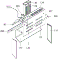
fig. 2 is an exploded schematic view of a draining device according to an embodiment of the present disclosure;
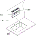
fig. 3 is a use scenario of a draining device according to an embodiment of the present application;
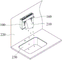
fig. 4 is another use scenario of a draining device according to an embodiment of the present application.
Wherein, the correspondence between the reference numerals and the component names in fig. 1 to 4 is:
100 draining devices, 110 shells, 111 through holes, 112 panels, 120 groove bodies, 130 slots, 140 chopstick spoon boxes, 150 water guide plates, 160 storage rods, 170 draining holes, 180 ultraviolet lamps, 190 controllers, 200 hanging pieces, 210 rags, 220 walls and 230 water tanks.
Detailed Description
In order to better understand the technical solutions described above, the technical solutions of the embodiments of the present application are described in detail below through the accompanying drawings and the specific embodiments, and it should be understood that the embodiments of the present application and the specific features in the embodiments are detailed descriptions of the technical solutions of the embodiments of the present application, and not limit the technical solutions of the present application, and the embodiments of the present application and the technical features in the embodiments of the present application may be combined with each other without conflict.
In some examples, as shown in fig. 1 to 4, a draining device 100 according to an embodiment of the present application includes: a housing 110, wherein a slot 120 is formed in the housing 110, a slot 130 is formed in the housing 110, and the slot 130 is used for inserting a cutter; the chopstick and spoon box 140 is inserted in the groove 120, and the bottom and the side wall of the chopstick and spoon box 140 are provided with draining holes 170; a sterilization module, disposed in the housing 110, for sterilizing the chopsticks in the chopstick spoon box 140 and the knife in the slot 130; the water guide plate 150 is connected to the housing 110, and the water guide plate 150 is formed with a slope surface positioned at the bottom of the housing 110.
It is understood that the draining device 100 provided in the embodiment of the present application is provided with a housing 110, a chopstick spoon case 140, a sterilization module, and a water guide plate 150. Specifically, the housing 110 is provided with a slot 120 and a slot 130, wherein the slot 130 is used for inserting a cutter, and a blocking opening of the cutter abuts against the housing 110 to fix the cutter. The chopstick and spoon box 140 is inserted into the groove body 120 to place the chopstick and spoon box 140, and the chopstick and spoon box 140 is used for placing the chopstick and spoon, so that the chopstick and spoon box is placed in a partition manner for the cutter and the chopstick and spoon, and is convenient to use. The water guide plate 150 is connected to the casing 110, and the water guide plate 150 is formed with a slope, water drained by the chopsticks and the chopsticks in the chopsticks and spoon box 140 and the cutters in the slots 130 can drop to the water guide plate 150, so that water in the casing 110 is discharged along the water guide plate 150, bacteria accumulated in the casing 110 are prevented from growing, the situation that the chopsticks and spoons are infected with bacteria is caused, and the health of a user is ensured. And the sterilization module is arranged in the shell 110, and generates a sterilization factor through the sterilization module so as to sterilize the chopstick spoon and the cutter, further inhibit bacteria breeding in the shell 110, improve the use safety of the chopstick spoon and the cutter and improve the reliability.
It is understood that the water tank 230 can be placed under the draining device 100, and the water guiding plate 150 can guide the drained water into the water tank 230, so as to treat the drained water, and reduce the cleaning workload.
Illustratively, the housing 110 and the chopstick and spoon box 140 and the water guide plate 150 can be made of plastic materials. The production cost is lower, the processing is convenient, the overall weight of the draining device 100 is lighter, the installation is easy, the draining device is not easy to be corroded by water, and the service life is prolonged.
In some examples, as shown in fig. 1 to 4, the draining device 100 further includes: the storage bar 160 is connected to the panel 112 of the housing 110.
It can be appreciated that the draining device 100 is further provided with a storage rod 160, the storage rod 160 is connected to the panel 112 of the housing 110, and the storage rod 160 can be used for storing the rag 210 and other objects, so as to drain the residual water of the rag 210, thereby improving the applicability. The storage bar 160 may be a U-shaped bar, two ends of the U-shaped bar are connected to the panel 112, and a space is reserved in the middle.
In some examples, the draining device 100 further includes: the heating element is disposed inside the storage bar 160 and is used for heating the storage bar 160.
It is understood that the storage bar 160 may have a hollow structure, and the heating element is disposed inside the storage bar 160 to heat the articles disposed on the storage bar 160, thereby accelerating evaporation of water and improving draining efficiency. Illustratively, the heating element may be a heating wire.
It can be appreciated that, in order to ensure electrical safety, a sealing member may be disposed on the storage rod 160 to ensure that moisture does not enter the storage rod 160, thereby causing a short circuit of the heating member and improving reliability.
In some examples, as shown in fig. 2, a plurality of the draining holes 170 are formed, and the draining holes 170 are arranged at intervals on the bottom and the side wall of the chopstick and spoon box 140.
It is appreciated that a plurality of drain holes 170 may be provided to increase the efficiency of draining the scoop box 140. Specifically, the plurality of draining holes 170 are arranged at intervals at the bottom and the side wall of the chopstick and spoon box 140, so that the draining efficiency of the bottom and the side wall of the chopstick and spoon box 140 is improved, the user experience is improved, the accumulation of residual water of the chopstick and spoon in the chopstick and spoon box 140 is avoided, and bacteria and microorganisms are prevented from breeding.
Illustratively, the draining hole 170 at the side wall of the chopstick and spoon box 140 may be a long strip hole, so as to increase the draining area, the draining hole 170 at the bottom of the chopstick and spoon box 140 may be a round hole, and the diameter of the round hole is smaller than the minimum diameter of the chopsticks, so as to avoid the chopsticks falling from the bottom of the chopstick and spoon box 140.
In some examples, as shown in fig. 2, the sterilization module is provided with an ultraviolet lamp 180, and the light emitted from the ultraviolet lamp 180 is directed toward the spoon case 140 and the cutter.
It can be appreciated that the sterilization module is provided with an ultraviolet lamp 180, and ultraviolet light emitted by the ultraviolet lamp 180 can irradiate the inside of the chopstick spoon box 140 through the draining hole 170 so as to sterilize and disinfect the chopstick spoon inside the chopstick spoon box 140, and meanwhile, can sterilize and disinfect the cutter inserted in the slot 130, kill residual bacteria and microorganisms of the chopstick spoon and the cutter while draining, improve the use safety, ensure the physical health of a user and improve the user experience.
In some examples, as shown in fig. 1 to 4, the draining device 100 further includes: and a controller 190 connected to the heating member and the ultraviolet lamp 180, respectively, wherein the controller 190 is used for controlling a heating temperature and a heating time of the heating member and a switching state of the ultraviolet lamp 180.
It will be appreciated that the draining device 100 is further provided with a controller 190, specifically, the controller 190 is electrically connected to the heating element and the ultraviolet lamp 180, and in case that the articles placed in the draining device 100 are detected, the controller 190 controls the ultraviolet lamp 180 to be turned on so as to emit ultraviolet light to irradiate the placed articles for sterilization. In the case of taking out the articles from the draining device 100, the controller 190 controls the ultraviolet lamp 180 to be turned off to save electricity. Under the condition that the object placement object is detected, the controller 190 can control the heating element to heat the object and control the heating time and the heating temperature of the heating element, so as to ensure efficient drying of the object, avoid overlong damage to the object between overhigh temperature and heating, and improve user experience.
In some examples, as shown in fig. 2, the draining device 100 further includes: the hanging member 200 is connected to the back plate of the housing 110, and is used for hanging the housing 110 on the wall 220.
It can be appreciated that the draining device 100 is further provided with a hanging member 200, the hanging member 200 is disposed at the back plate of the housing 110 to suspend the draining device 100 on the wall 220, and further, the draining device 100 is suspended on the wall 220 above the water tank 230 to drop the drained water into the water tank 230, so as to facilitate cleaning operation.
For example, the hanging member 200 may be a plate body, the plate body is disposed at the back plate, and the plate body is provided with a connecting hole, and the hanging member may be screwed into the wall 220 through a bolt passing through the connecting hole, so as to hang the draining device 100 on the wall 220. Or the hanging hook is penetrated through the connecting hole, and the draining device 100 is hung on the wall 220 by using the hanging hook.
In some examples, the hanging member 200 is a sticker for adhering the housing 110 to the wall 220.
It can be appreciated that the hanging member 200 may be a glue, so as to attach the housing 110 to the wall 220, and the connection manner is quick, simple and convenient, and convenient to replace, and will not damage the wall 220. The selected adhesive tape has good waterproof property.
In some examples, the panel 112 of the housing 110 is provided with a plurality of through holes 111, and the plurality of through holes 111 are arranged at intervals.
It can be understood that the panel 112 of the housing 110 is provided with a plurality of through holes 111 to increase air permeability and improve draining efficiency, and meanwhile, high temperature generated by the heating element in the storage rod 160 is transferred to the inside of the housing 110 through the through holes 111 to dry the chopsticks, spoon and knife, thereby further improving draining efficiency. And a plurality of through holes 111 are arranged at intervals, the intervals of the adjacent through holes 111 are the same, the attractive appearance is improved, long round holes can be selected for the through holes 111, the ventilation area is improved, and the punching quantity is reduced.
In some examples, the slots 130 are provided in a plurality, and the slots 130 are arranged at intervals; the plurality of grooves 120 are formed, and the plurality of grooves 120 are arranged at intervals.
It can be appreciated that the draining device 100 can be provided with a plurality of slots 130 for placing a plurality of cutters, and the slot 120 can be provided with a plurality of chopsticks and spoon boxes 140, so that the one-time draining efficiency of the draining device 100 can be improved. The plurality of slots 130 are spaced apart to avoid interference of the plurality of cutters.
In the description of the present utility model, it should be understood that the directions or positional relationships indicated by the terms "upper", "lower", "left", "right", "front", "rear", etc. are based on the directions or positional relationships shown in the drawings, are merely for convenience of describing the present utility model and simplifying the description, and do not indicate or imply that the devices or units referred to must have a specific direction, be constructed and operated in a specific direction, and thus should not be construed as limiting the present utility model.
In the description of the present specification, the terms "one embodiment," "some embodiments," "particular embodiments," and the like, mean that a particular feature, structure, material, or characteristic described in connection with the embodiment or example is included in at least one embodiment or example of the present utility model. In this specification, schematic representations of the above terms do not necessarily refer to the same embodiment or example. Furthermore, the particular features, structures, materials, or characteristics described may be combined in any suitable manner in any one or more embodiments or examples.
The above is only a preferred embodiment of the present utility model, and is not intended to limit the present utility model, but various modifications and variations can be made to the present utility model by those skilled in the art. Any modification, equivalent replacement, improvement, etc. made within the spirit and principle of the present utility model should be included in the protection scope of the present utility model.
Claims (10)
1. A draining device, comprising:
the shell is provided with a groove body and a slot, and the slot is used for inserting a cutter;
the chopstick and spoon box is inserted into the groove body, and draining holes are formed in the bottom and the side wall of the chopstick and spoon box;
the sterilization module is arranged in the shell and is used for sterilizing chopsticks in the chopstick and spoon box and the cutters in the slots;
the water guide plate is connected to the shell, a slope is formed on the water guide plate, and the slope is located at the bottom of the shell.
2. The drain device according to claim 1, further comprising:
the storage rod is connected to the panel of the shell.
3. The drain device according to claim 2, further comprising:
the heating piece is arranged inside the storage rod and used for heating the storage rod.
4. The draining device according to claim 1, wherein,
the plurality of the draining holes are formed and are distributed at intervals at the bottom and the side wall of the chopstick spoon box.
5. The draining device according to claim 3, wherein,
the sterilization module is provided with an ultraviolet lamp, and light emitted by the ultraviolet lamp is used for facing the chopstick spoon box and the cutter.
6. The drain device according to claim 5, further comprising:
and the controller is respectively connected with the heating piece and the ultraviolet lamp and is used for controlling the heating temperature and the heating time of the heating piece and the on-off state of the ultraviolet lamp.
7. The drain device according to claim 1, further comprising:
and the hanging piece is connected to the backboard of the shell and used for hanging the shell on a wall body.
8. The draining device of claim 7, wherein,
the pendant is a sticky note and is used for pasting the shell on the wall body.
9. The draining device according to claim 1, wherein,
the panel of the shell is provided with a plurality of through holes, and the through holes are distributed at intervals.
10. The draining device according to claim 1, wherein,
a plurality of slots are formed, and the slots are distributed at intervals;
the groove bodies are arranged in a plurality of mode at intervals.
Priority Applications (1)
| Application Number | Priority Date | Filing Date | Title |
|---|---|---|---|
| CN202223195105.6U CN219147415U (en) | 2022-11-29 | 2022-11-29 | Draining device |
Applications Claiming Priority (1)
| Application Number | Priority Date | Filing Date | Title |
|---|---|---|---|
| CN202223195105.6U CN219147415U (en) | 2022-11-29 | 2022-11-29 | Draining device |
Publications (1)
| Publication Number | Publication Date |
|---|---|
| CN219147415U true CN219147415U (en) | 2023-06-09 |
Family
ID=86637659
Family Applications (1)
| Application Number | Title | Priority Date | Filing Date |
|---|---|---|---|
| CN202223195105.6U Active CN219147415U (en) | 2022-11-29 | 2022-11-29 | Draining device |
Country Status (1)
| Country | Link |
|---|---|
| CN (1) | CN219147415U (en) |
-
2022
- 2022-11-29 CN CN202223195105.6U patent/CN219147415U/en active Active
Similar Documents
| Publication | Publication Date | Title |
|---|---|---|
| KR20130015240A (en) | Apparatus for caring clothes | |
| CN102309266A (en) | Disinfecting cutter holder and method for disinfecting cutter by using same | |
| CN219147415U (en) | Draining device | |
| CN205321763U (en) | Kitchen utensils and appliances storing compartment | |
| KR200416276Y1 (en) | Knifes holder for kitchen | |
| KR200399835Y1 (en) | Storage Container for Simultaneous drying of a kitchen knife, a kitchen board and a dishtowel | |
| CN213488490U (en) | Knife and chopstick storage device with sterilization and disinfection functions | |
| CN210663820U (en) | Chopping block cutter subassembly degassing unit | |
| CN211561180U (en) | Kitchen ware disinfection device with first accommodating cavity and second accommodating cavity in split mode | |
| CN211985333U (en) | Kitchen drying and sterilizing device | |
| KR200395086Y1 (en) | Kitchin dryer | |
| CN112316169A (en) | Knife and chopsticks sterilizer | |
| CN211129993U (en) | Tableware box with disinfection function | |
| CN202236460U (en) | Wall-hung towel and underwear disinfecting cabinet | |
| CN211096260U (en) | Wall-mounted disinfection cylinder | |
| CN212730456U (en) | Tableware and kitchen ware sterilizer | |
| CN213127907U (en) | Disinfection storage rack | |
| CN219147433U (en) | Drying sterilizer | |
| CN216456133U (en) | Intelligence touch screen cutter chopping block sterilizer | |
| CN205338794U (en) | Multifunctional towels racks | |
| CN212140286U (en) | Clean towel rack | |
| CN220275997U (en) | Basin placed type disinfection cabinet | |
| CN217339458U (en) | Sterilizing machine | |
| CN213282470U (en) | Tableware storage device | |
| CN214910893U (en) | Sterilization machine |
Legal Events
| Date | Code | Title | Description |
|---|---|---|---|
| GR01 | Patent grant | ||
| GR01 | Patent grant |