CN219131663U - Numerical control machine tool convenient for chip removal - Google Patents
Numerical control machine tool convenient for chip removal Download PDFInfo
- Publication number
- CN219131663U CN219131663U CN202320274310.7U CN202320274310U CN219131663U CN 219131663 U CN219131663 U CN 219131663U CN 202320274310 U CN202320274310 U CN 202320274310U CN 219131663 U CN219131663 U CN 219131663U
- Authority
- CN
- China
- Prior art keywords
- control machine
- machine tool
- box body
- numerical control
- chip removal
- Prior art date
- Legal status (The legal status is an assumption and is not a legal conclusion. Google has not performed a legal analysis and makes no representation as to the accuracy of the status listed.)
- Active
Links
- 239000002173 cutting fluid Substances 0.000 claims abstract description 28
- 238000005520 cutting process Methods 0.000 claims abstract description 11
- 238000011084 recovery Methods 0.000 claims description 12
- 238000004140 cleaning Methods 0.000 claims description 11
- 239000007788 liquid Substances 0.000 claims description 6
- 238000007789 sealing Methods 0.000 claims description 5
- 239000000463 material Substances 0.000 claims description 3
- XEEYBQQBJWHFJM-UHFFFAOYSA-N Iron Chemical compound [Fe] XEEYBQQBJWHFJM-UHFFFAOYSA-N 0.000 abstract description 60
- 229910052742 iron Inorganic materials 0.000 abstract description 30
- 230000000694 effects Effects 0.000 abstract description 8
- 238000009825 accumulation Methods 0.000 abstract description 3
- 238000007599 discharging Methods 0.000 abstract 2
- 238000000926 separation method Methods 0.000 description 5
- 230000003044 adaptive effect Effects 0.000 description 1
- 230000004075 alteration Effects 0.000 description 1
- 230000009286 beneficial effect Effects 0.000 description 1
- 239000002826 coolant Substances 0.000 description 1
- 239000000110 cooling liquid Substances 0.000 description 1
- 230000007547 defect Effects 0.000 description 1
- 238000010586 diagram Methods 0.000 description 1
- 239000012535 impurity Substances 0.000 description 1
- 238000004519 manufacturing process Methods 0.000 description 1
- 239000002184 metal Substances 0.000 description 1
- 229910052751 metal Inorganic materials 0.000 description 1
- 238000000034 method Methods 0.000 description 1
- 238000012986 modification Methods 0.000 description 1
- 230000004048 modification Effects 0.000 description 1
- 238000006467 substitution reaction Methods 0.000 description 1
Images
Classifications
-
- Y—GENERAL TAGGING OF NEW TECHNOLOGICAL DEVELOPMENTS; GENERAL TAGGING OF CROSS-SECTIONAL TECHNOLOGIES SPANNING OVER SEVERAL SECTIONS OF THE IPC; TECHNICAL SUBJECTS COVERED BY FORMER USPC CROSS-REFERENCE ART COLLECTIONS [XRACs] AND DIGESTS
- Y02—TECHNOLOGIES OR APPLICATIONS FOR MITIGATION OR ADAPTATION AGAINST CLIMATE CHANGE
- Y02P—CLIMATE CHANGE MITIGATION TECHNOLOGIES IN THE PRODUCTION OR PROCESSING OF GOODS
- Y02P70/00—Climate change mitigation technologies in the production process for final industrial or consumer products
- Y02P70/10—Greenhouse gas [GHG] capture, material saving, heat recovery or other energy efficient measures, e.g. motor control, characterised by manufacturing processes, e.g. for rolling metal or metal working
Landscapes
- Auxiliary Devices For Machine Tools (AREA)
Abstract
The utility model discloses a numerical control machine tool convenient for chip removal, which relates to the technical field of numerical control machine tools and comprises a power box, a box body, a chuck and a cutting head, wherein two V-shaped inclined plates are arranged below the cutting head in the box body, a collecting groove is arranged at the intersection of the two inclined plates, one end of the collecting groove extends to the outer side of the box body, a discharging pipe is arranged below the collecting groove, a filter screen is arranged at the bottom of the collecting groove, a rotating shaft is arranged in the collecting groove in a rotating mode, a spiral auger is fixedly arranged on the rotating shaft, a motor is fixedly arranged at one end of the collecting groove, the driving end of the motor is connected with the rotating shaft, cutting fluid and scrap iron can be separated through the filter screen in the collecting groove, the scrap iron in the collecting groove can be conveyed to the outer side of the box body through rotation of the spiral auger, and then the scrap iron is discharged through the discharging pipe, so that the scrap iron is cleaned timely, and the effect of the cutting fluid is prevented from being excessively influenced due to accumulation of the scrap iron.
Description
Technical Field
The utility model relates to the technical field of numerical control machine tools, in particular to a numerical control machine tool convenient for chip removal.
Background
The numerical control machine tool is an automatic machine tool provided with a program control system, parts can be automatically machined according to the shape and the size required by a drawing through a program instruction which is pre-introduced, and a large amount of metal scraps can be generated when the parts are machined, so that the interior of the machine tool is required to be cleaned frequently.
As in the utility model patent with publication number CN211565290U, a numerical control machine tool convenient for chip removal is disclosed, which can save the physical strength and time during manual collection, improve the working efficiency, simplify the chip collection mode, ensure the continuous normal operation of the machine tool, prevent the chip clearing work from influencing the normal production of the factory, save the manpower resources and improve the practicability and reliability by automatically collecting chips; the device comprises a lathe bed, a main motor, a chuck, a transverse moving device, a turret, a cutter head and a turning tool, wherein the left side of the top end of the lathe bed is connected with the bottom end of the main motor, the left end of the chuck is arranged at the right end of the main motor, the bottom end of the transverse moving device is transversely arranged at the right rear side of the top end of the lathe bed and can move left and right at the top end of the lathe bed, and the bottom end of the turret is arranged at the top end of the transverse moving device; the device also comprises a conveying bin, four groups of supporting legs, a collecting bin, two groups of conveying shafts, two groups of conveying wheels, a conveying chain plate, two groups of flanges and a first bracket.
However, the device can't be timely outside with iron fillings discharge equipment, when the iron fillings pile up too much, influenced the separation effect of iron fillings and coolant liquid, excellent in use effect.
Disclosure of Invention
Aiming at the defects of the prior art, the utility model provides a numerical control machine tool convenient for chip removal, which solves the technical problem that the existing device cannot timely discharge scrap iron out of equipment, and the separation effect of scrap iron and cooling liquid is affected.
In order to achieve the above purpose, the utility model is realized by the following technical scheme: the utility model provides a digit control machine tool convenient to chip removal, includes headstock, box, chuck, cutting head, be located in the box cutting head below is equipped with two swash plates that are the V type and place, two the crossing department of swash plate is equipped with the collecting vat, collecting vat one end extends to the box outside and be equipped with row material pipe in the below, the collecting vat bottom is equipped with the filter screen, the collecting vat rotation is provided with the pivot, fixed mounting has the spiral auger in the pivot, the collecting vat is located box outside one end fixed mounting has the motor, the motor drive end with the pivot is connected.
Preferably, the collecting tank is arranged obliquely, and one end of the collecting tank, which is positioned outside the box body, is higher than one end of the collecting tank, which is positioned inside the box body.
Preferably, a cutting fluid recovery cavity is arranged on the outer side of the lower portion of the collecting tank in the box body, and a liquid discharge pipe is connected to the bottom of the cutting fluid recovery cavity.
Preferably, a cleaning opening is formed in one side of the cutting fluid recovery cavity on the side wall of the box body, and the cleaning opening is plugged through a sealing door.
Preferably, vibration motors are fixedly arranged below the two sloping plates.
Advantageous effects
The utility model provides a numerical control machine tool convenient for chip removal, which has the following beneficial effects:
1. scrap iron and cutting fluid can be collected through the two inclined plates which are arranged in a V shape, the cutting fluid and the scrap iron can be separated through a filter screen in the collecting tank, the scrap iron in the collecting tank can be conveyed to the outer side of the box body through spiral auger rotation, and then the scrap iron is discharged through the discharge pipe, so that timely cleaning of the scrap iron is realized, and the separation effect of the cutting fluid due to excessive accumulation of the scrap iron is prevented;
2. the flow of cutting fluid out of the collecting tank can be reduced through the obliquely arranged collecting tank, and the separation effect is improved;
3. the sliding speed of scrap iron on the inclined plate can be accelerated by starting the vibrating motor, and the scrap iron on the inclined plate is prevented from accumulating.
Drawings
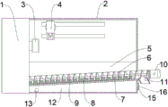
FIG. 1 is a schematic diagram of the front internal structure of the present utility model;
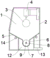
fig. 2 is a schematic side view of the internal structure of the present utility model.
In the figure: 1. a power box; 2. a case; 3. a chuck; 4. a cutting head; 5. a sloping plate; 6. a collection tank; 7. a filter screen; 8. a rotating shaft; 9. a spiral auger; 10. a motor; 11. a discharge pipe; 12. a cutting fluid recovery chamber; 13. a liquid discharge pipe; 14. a vibration motor; 15. cleaning the mouth; 16. sealing the door.
Detailed Description
The technical solutions in the embodiments of the present utility model will be clearly and completely described below with reference to the accompanying drawings in the embodiments of the present utility model.
Referring to fig. 1-2, the present utility model provides a technical solution: the utility model provides a digit control machine tool convenient to chip removal, including headstock 1, box 2, chuck 3, cutting head 4, be located cutting head 4 below in the box 2 and be equipped with two swash plates 5 that are the V type and place, two swash plates 5 crossing department is equipped with collecting vat 6, collecting vat 6 one end extends to the box 2 outside and is equipped with row material pipe 11 in the below, collecting vat 6 bottom is equipped with filter screen 7, collecting vat 6 internal rotation is provided with pivot 8, fixed mounting has spiral auger 9 in the pivot 8, collecting vat 6 is located box 2 outside one end fixed mounting and has motor 10, the motor 10 drive end is connected with pivot 8.
In this embodiment, two swash plates 5 that are V type and place are used for collecting the iron fillings and the cutting fluid that the top dropped, drop iron fillings and the cutting fluid on swash plate 5 and can slide to collecting vat 6 in, can separate cutting fluid and iron fillings through filter screen 7, drive pivot 8 through motor 10 and can make spiral auger 9 rotate to can carry the iron fillings in the collecting vat 6 to the box 2 outside, then discharge through discharge pipe 11.
As an embodiment of the utility model, the collecting tank 6 is arranged obliquely, and the end of the collecting tank 6 located outside the tank 2 is higher than the end located inside the tank 2.
In this embodiment, the flow of the cutting fluid out through the collecting tank 6 can be reduced by the collecting tank 6 being provided obliquely.
As an embodiment of the utility model, a cutting fluid recovery cavity 12 is arranged in the box body 2 below and outside the collecting tank 6, and a liquid discharge pipe 13 is connected to the bottom of the cutting fluid recovery cavity 12.
In this embodiment, the cutting fluid can be collected by the cutting fluid collection chamber 12, and the cutting fluid can be discharged to the outside of the casing 2 through the drain pipe 13.
As an embodiment of the utility model, a cleaning opening 15 is formed in the side wall of the case 2 at the side of the cutting fluid recovery chamber 12, and the cleaning opening 15 is blocked by a sealing door 16.
In this embodiment, the impurities precipitated in the cutting fluid recovery chamber 12 can be cleaned through the cleaning port 15 provided, and the cleaning port 15 can be blocked by the sealing door 16.
As an embodiment of the present utility model, a vibration motor 14 is fixedly installed under both swash plates 5.
In this embodiment, the swash plate 5 is vibrated by the vibration motor 14, so that the sliding speed of the iron pieces on the swash plate 5 is accelerated.
All electric components in the scheme are connected with an adaptive power supply through wires by a person skilled in the art, and an appropriate controller is selected according to actual conditions so as to meet control requirements, specific connection and control sequences, and the electric connection is completed by referring to the following working principles in the working sequence among the electric components, wherein the detailed connection means are known in the art, and the following main description of the working principles and processes is omitted from the description of electric control.
The working principle and the use flow of the utility model are that a workpiece is clamped on a chuck 3, and the workpiece is cut by a cutting head 4; scrap iron generated during cutting falls onto the inclined plate 5 through dead weight, the sliding speed of the scrap iron on the inclined plate 5 can be accelerated by starting the vibration motor 14, the fallen scrap iron can enter the collecting tank 6, cutting fluid can be separated from the scrap iron through the filter screen 7, the cutting fluid enters the cutting fluid recovery cavity 12 through the dead weight, and then is discharged through the liquid discharge pipe 13; scrap iron is conveyed out of the box body 2 through the spiral auger 9 and discharged through the discharge pipe 11, timely cleaning of the scrap iron is achieved, and the separation effect of cutting fluid is prevented from being influenced due to excessive accumulation of the scrap iron.
Although embodiments of the present utility model have been shown and described, it will be understood by those skilled in the art that various changes, modifications, substitutions and alterations can be made therein without departing from the principles and spirit of the utility model, the scope of which is defined in the appended claims and their equivalents.
Claims (5)
1. The utility model provides a digit control machine tool convenient to chip removal, includes headstock (1), box (2), chuck (3), cutting head (4), its characterized in that, be located in box (2) cutting head (4) below is equipped with two swash plates (5) that are V type and place, two crossing department of swash plate (5) is equipped with collecting vat (6), collecting vat (6) one end extends to box (2) outside and be equipped with row material pipe (11) in the below, collecting vat (6) bottom is equipped with filter screen (7), collecting vat (6) rotation is provided with pivot (8), fixed mounting has spiral auger (9) on pivot (8), collecting vat (6) are located box (2) outside one end fixed mounting has motor (10), motor (10) drive end with pivot (8) are connected.
2. The numerical control machine tool convenient for chip removal according to claim 1, wherein the collecting tank (6) is obliquely arranged, and one end of the collecting tank (6) located at the outer side of the box body (2) is higher than one end located at the inner side of the box body (2).
3. The numerical control machine tool convenient for chip removal according to claim 1, wherein a cutting fluid recovery cavity (12) is arranged on the outer side of the box body (2) below the collecting tank (6), and a liquid discharge pipe (13) is connected to the bottom of the cutting fluid recovery cavity (12).
4. A numerical control machine tool convenient for chip removal according to claim 3, characterized in that a cleaning opening (15) is formed in the side wall of the box body (2) and located at one side of the cutting fluid recovery cavity (12), and the cleaning opening (15) is plugged through a sealing door (16).
5. A numerical control machine tool for facilitating chip removal according to claim 1, characterized in that vibration motors (14) are fixedly mounted below both the sloping plates (5).
Priority Applications (1)
| Application Number | Priority Date | Filing Date | Title |
|---|---|---|---|
| CN202320274310.7U CN219131663U (en) | 2023-02-22 | 2023-02-22 | Numerical control machine tool convenient for chip removal |
Applications Claiming Priority (1)
| Application Number | Priority Date | Filing Date | Title |
|---|---|---|---|
| CN202320274310.7U CN219131663U (en) | 2023-02-22 | 2023-02-22 | Numerical control machine tool convenient for chip removal |
Publications (1)
| Publication Number | Publication Date |
|---|---|
| CN219131663U true CN219131663U (en) | 2023-06-06 |
Family
ID=86594121
Family Applications (1)
| Application Number | Title | Priority Date | Filing Date |
|---|---|---|---|
| CN202320274310.7U Active CN219131663U (en) | 2023-02-22 | 2023-02-22 | Numerical control machine tool convenient for chip removal |
Country Status (1)
| Country | Link |
|---|---|
| CN (1) | CN219131663U (en) |
Cited By (3)
| Publication number | Priority date | Publication date | Assignee | Title |
|---|---|---|---|---|
| CN117583944A (en) * | 2024-01-17 | 2024-02-23 | 爱派尔(常州)数控科技有限公司 | Gantry machining machine tool |
| CN119347523A (en) * | 2024-12-24 | 2025-01-24 | 江西刀父科技有限公司 | Chip removal device for machine tool cutting |
| CN120861858A (en) * | 2025-07-29 | 2025-10-31 | 杭州潇磊机械有限公司 | Intelligent turning device and method based on embroidery machine cam production |
-
2023
- 2023-02-22 CN CN202320274310.7U patent/CN219131663U/en active Active
Cited By (4)
| Publication number | Priority date | Publication date | Assignee | Title |
|---|---|---|---|---|
| CN117583944A (en) * | 2024-01-17 | 2024-02-23 | 爱派尔(常州)数控科技有限公司 | Gantry machining machine tool |
| CN117583944B (en) * | 2024-01-17 | 2024-03-19 | 爱派尔(常州)数控科技有限公司 | Gantry machining machine tool |
| CN119347523A (en) * | 2024-12-24 | 2025-01-24 | 江西刀父科技有限公司 | Chip removal device for machine tool cutting |
| CN120861858A (en) * | 2025-07-29 | 2025-10-31 | 杭州潇磊机械有限公司 | Intelligent turning device and method based on embroidery machine cam production |
Similar Documents
| Publication | Publication Date | Title |
|---|---|---|
| CN219131663U (en) | Numerical control machine tool convenient for chip removal | |
| CN217071695U (en) | Coolant liquid filter equipment for digit control machine tool | |
| CN211305026U (en) | Automatic collect collection device of waste material and coolant liquid | |
| CN112520867A (en) | Sewage recycling device based on computer control | |
| CN215392686U (en) | Numerical control milling machine with cleaning function | |
| CN220839228U (en) | Chip removal mechanism for numerical control machine tool | |
| CN117900898B (en) | Machine tool chip removing device and operation method thereof | |
| CN211464858U (en) | Cleaning type water and chip separation lathe | |
| CN210755436U (en) | Discharging device is used in planer processing convenient to collect piece | |
| CN219325027U (en) | Lathe processing sweeps recovery unit | |
| CN220051078U (en) | Chip removal cleaning device for digit control machine tool | |
| CN217513482U (en) | Scraper chip removal machine | |
| CN213795497U (en) | Automatic cleaning system for drilling and milling composite machine tool | |
| CN214109058U (en) | Automatic cutting platform with garbage collection device | |
| CN111168473A (en) | Multifunctional intelligent circulating numerical control machining equipment | |
| CN210588426U (en) | Cutting fluid circulating system of cutting device | |
| CN213164060U (en) | Universal turning and milling composite device | |
| CN211562090U (en) | Solid-liquid separation device for cutting feed liquid of machine tool | |
| CN220921682U (en) | Chip removal device of vertical numerical control machining center | |
| CN215876480U (en) | Waste collecting and separating device of lathe | |
| CN223917385U (en) | Numerical control milling machine convenient to clearance | |
| CN218363588U (en) | Chip removal mechanism of gantry machining center | |
| CN215145035U (en) | Semi-automatic bottom milling machine for door and window handle seat | |
| CN222945082U (en) | Cooling liquid circulating device for vertical machining center machine | |
| CN219542472U (en) | Mixed turning liquid autosegregation high-speed machining center |
Legal Events
| Date | Code | Title | Description |
|---|---|---|---|
| GR01 | Patent grant | ||
| GR01 | Patent grant |