CN219068112U - Multi-grid battery piece with adjusting function - Google Patents
Multi-grid battery piece with adjusting function Download PDFInfo
- Publication number
- CN219068112U CN219068112U CN202222974093.0U CN202222974093U CN219068112U CN 219068112 U CN219068112 U CN 219068112U CN 202222974093 U CN202222974093 U CN 202222974093U CN 219068112 U CN219068112 U CN 219068112U
- Authority
- CN
- China
- Prior art keywords
- battery piece
- regulation function
- screw rod
- roof
- balls
- Prior art date
- Legal status (The legal status is an assumption and is not a legal conclusion. Google has not performed a legal analysis and makes no representation as to the accuracy of the status listed.)
- Active
Links
Images


Classifications
-
- Y—GENERAL TAGGING OF NEW TECHNOLOGICAL DEVELOPMENTS; GENERAL TAGGING OF CROSS-SECTIONAL TECHNOLOGIES SPANNING OVER SEVERAL SECTIONS OF THE IPC; TECHNICAL SUBJECTS COVERED BY FORMER USPC CROSS-REFERENCE ART COLLECTIONS [XRACs] AND DIGESTS
- Y02—TECHNOLOGIES OR APPLICATIONS FOR MITIGATION OR ADAPTATION AGAINST CLIMATE CHANGE
- Y02E—REDUCTION OF GREENHOUSE GAS [GHG] EMISSIONS, RELATED TO ENERGY GENERATION, TRANSMISSION OR DISTRIBUTION
- Y02E10/00—Energy generation through renewable energy sources
- Y02E10/50—Photovoltaic [PV] energy
Abstract
The utility model discloses a multi-grid battery piece with an adjusting function, which relates to the technical field of multi-grid battery pieces and solves the problem that the adjusting angle of the battery piece is relatively fixed.
Description
Technical Field
The utility model relates to the technical field of multi-grid battery pieces, in particular to a multi-grid battery piece with an adjusting function.
Background
Along with the development of new energy, the photovoltaic industry is continuously growing, and the photovoltaic cell is rapidly developed and continuously transformed. The battery assembly is formed by welding a plurality of battery pieces through welding strips to form a battery string, and then welding the battery string through bus welding. Through the development and innovation of the battery piece, MBB (multi-main grid) battery piece becomes the main stream, and the photoelectric conversion efficiency can be improved by 0.2%, so that the cost is reduced. And the MBB battery piece has less silver paste and finer silver wires, and the positive silver consumption is saved by 25% -35%. In order to reduce the resistance influence of the photovoltaic module, the more accurate and better the welding strip and the battery piece are in butt joint, the higher the welding strip positioning requirement on the battery piece serial welding machine is.
Traditionally, the battery piece needs manual adjustment battery piece in the use, makes the angle of battery piece aim at the angle of sunshine irradiation, leads to complex operation, consequently the many bars battery piece of being convenient for adjust has been proposed to someone, for example the five bars line polycrystalline battery piece of publication number CN213937812U, and its technical scheme is: the solar cell comprises a cell, the second drive arrangement is connected to the cell lower extreme, first drive arrangement is connected to the second drive arrangement lower extreme, the cell right-hand member passes through bolt fixed mounting positioner, positioner inner wall right side threaded connection fixing device, positioner includes the support, the support passes through bolt fixed mounting the cell right-hand member, the inside top of support passes through bolt fixed mounting convex lens, the inside right-hand member of support is equipped with infrared detector, the inside bottom joint gasket of support, infrared detector fixes the inside of fixing device, fixing device includes the cloud platform, and the beneficial effect of the utility model is: the effect that the battery piece autonomously adjusts the irradiation angle is achieved without operation, so that the solar energy absorption efficiency of the battery piece is improved, the convex mirror is installed through the bracket, light is converged on the convex mirror to form light spots on the gasket through sunlight irradiation, the light spots are irradiated through the infrared detector, the infrared detector is overlapped with the light spots, the effect of controlling the adjustment angle is achieved, the effect that the battery piece autonomously adjusts the irradiation angle is achieved, the irradiation area of the battery piece is maintained to be the largest is achieved, and therefore the effect that the solar energy absorption efficiency of the battery piece is improved without operation is achieved;
however, the adjusting device can only drive the multi-grid battery piece to turn up and down along with the rising and falling of the sun in the same plane, the angle and the amplitude of the turning adjustment are relatively fixed, the battery piece cannot be subjected to multi-angle rotation adjustment, and the practicability is poor.
Disclosure of Invention
The utility model aims to provide a multi-grid battery piece convenient for multi-angle adjustment so as to solve the problems in the background art.
In order to achieve the above purpose, the present utility model provides the following technical solutions: the utility model provides a multi-grid battery piece with regulatory function, includes the stand, still including installing the end cover on stand top, the slide rail has been seted up all around in the stand, slide rail inner bottom fixed mounting has servo motor, servo motor top power take off end fixed connection screw rod bottom's power input end, screw rod surface threaded connection has the screw rod piece, screw rod piece top has the mount through bearing movable mounting, there is the vaulting pole bottom through pivot fixed mounting in the mount, the vaulting pole top is through pivot fixed connection roof bottom middle-end all around.
Preferably, the electric balls are fixedly arranged on two sides in the bottom sleeve, the rotary balls are inserted in the bottom sleeve, the rotary balls are fixedly arranged at the center position of the bottom of the top plate, the electric balls are arranged on two sides in the bottom sleeve, and the rotary balls at the center position of the bottom of the top plate are inserted in the bottom sleeve so as to facilitate the rotation of the top plate under the rotation action of the rotary balls at the bottom in the bottom sleeve, so that the top plate is rotationally adjusted.
Preferably, the L-shaped slots are formed in four corners in the top plate, L-shaped cutting bars are inserted in the L-shaped slots, the L-shaped cutting bars are integrally formed in four corners at the bottom of the protection plate, clamping holes are formed in the central positions of two ends in the L-shaped cutting bars, a plurality of grid battery pieces are fixedly mounted on the top of the top plate through fixing screws, and the L-shaped cutting bars arranged in four corners of the bottom of the protection plate are inserted in the L-shaped slots in the four corners of the top plate so as to facilitate the fixed mounting and the dismounting of the protection plate.
Preferably, the limiting ball is inserted into the clamping hole, the periphery of the outer side of the limiting ball is fixedly connected with the two inner side walls of the L-shaped slot through the limiting spring, the limiting ball is inserted into the clamping hole, the periphery of the middle part of the limiting ball is connected with the two inner side walls of the L-shaped slot through the limiting spring, so that the limiting ball is inserted into the clamping hole, the protection plate is limited and fixed, and the protection plate is convenient to install and detach.
Preferably, the PVC transparent plate is installed at the top in the guard plate through the set screw, and the transparent guard plate of top installation PVC in the guard plate can be convenient for can not influence the use of many bars battery piece when protecting many bars battery piece.
Preferably, the base is welded at the bottom end of the upright post, and the base is welded at the bottom end of the upright post, so that the multi-grid battery piece can be conveniently and fixedly installed.
Compared with the prior art, the utility model has the beneficial effects that:
according to the utility model, the slide rails are arranged on the periphery in the stand column, the servo motor connecting screw is arranged at the bottom end, the outer side of the mahjong screw is in threaded connection with the screw block, the fixing frame is arranged through the bearing, the supporting rods in the fixing frame, the two ends of which are provided with the rotating shafts, are connected with the top plate of which the surface is provided with the multi-grid battery piece, the rotating ball is arranged at the center position of the bottom of the top plate and inserted into the bottom sleeve, so that the rotating ball can conveniently rotate in the bottom sleeve and slide up and down on the surface of the screw rod in cooperation with the four groups of supporting rods and the screw block, thereby driving the top plate and the multi-grid battery piece to be used for multi-angle adjustment, the angle adjustment range is larger, and the practicability is stronger.
Additional aspects and advantages of the utility model will be set forth in part in the description which follows, and in part will be obvious from the description, or may be learned by practice of the utility model.
Drawings
The foregoing and/or additional aspects and advantages of the utility model will become apparent and may be better understood from the following description of embodiments taken in conjunction with the accompanying drawings in which:
FIG. 1 is a schematic diagram of the overall structure of the present utility model;
FIG. 2 is a schematic view of the structure of the column according to the present utility model;
FIG. 3 is a schematic diagram of a screw block structure according to the present utility model;
FIG. 4 is a schematic diagram of an L-shaped slot according to the present utility model.
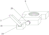
In the figure: 1-a top plate; 2-multi-grid battery pieces; 3-stay bars; 4-bottom sleeve; 5-screw; 6-stand columns; 7-a base; 8-a servo motor; 9-screw blocks; 10-sliding rails; 11-L-shaped cuttings; 12-clamping holes; 13-protecting plates; 14-PVC transparent plate; 15-L-shaped slots; 16-rotating shaft; 17-an electric ball; 18-turning ball; 19-a fixing frame; 20-bearing; 21-limit balls; 22-limit springs.
Detailed Description
Embodiments of the present utility model are described in detail below, examples of which are illustrated in the accompanying drawings, wherein like or similar reference numerals refer to like or similar elements or elements having like or similar functions throughout. The embodiments described below by referring to the drawings are illustrative only and are not to be construed as limiting the utility model.
In the description of the present utility model, it should be understood that references to orientation descriptions such as upper, lower, front, rear, left, right, etc. are based on the orientation or positional relationship shown in the drawings, are merely for convenience of description of the present utility model and to simplify the description, and do not indicate or imply that the apparatus or elements referred to must have a particular orientation, be constructed and operated in a particular orientation, and thus should not be construed as limiting the present utility model.
In the description of the present utility model, a number means one or more, a number means two or more, and greater than, less than, exceeding, etc. are understood to not include the present number, and above, below, within, etc. are understood to include the present number. The description of the first and second is for the purpose of distinguishing between technical features only and should not be construed as indicating or implying relative importance or implicitly indicating the number of technical features indicated or implicitly indicating the precedence of the technical features indicated.
In the description of the present utility model, unless explicitly defined otherwise, terms such as arrangement, installation, connection, etc. should be construed broadly and the specific meaning of the terms in the present utility model can be reasonably determined by a person skilled in the art in combination with the specific contents of the technical scheme.
Example 1
Referring to fig. 1, 2 and 3, a multi-grid battery piece with an adjusting function in the illustration comprises a stand column 6 and a bottom sleeve 4 arranged at the top end of the stand column 6, a slide rail 10 is arranged around in the stand column 6, a servo motor 8 is fixedly arranged at the inner bottom end of the slide rail 10, a power output end at the top end of the servo motor 8 is fixedly connected with a power input end at the bottom end of a screw 5, a screw block 9 is connected with the surface of the screw 5 through threads, a fixing frame 19 is movably arranged at the top end of the screw block 9 through a bearing 20, a supporting rod 3 bottom end is fixedly arranged in the fixing frame 19 through a rotating shaft 16, and the top end of the supporting rod 3 is fixedly connected with the middle end around the bottom of a top plate 1 through the rotating shaft 16.
It should be noted that: in this scheme, the stand 6 of design sets up slide rail 10 all around, installs servo motor 8 and connecting screw rod 5 in slide rail 10 bottom, runs through stand 6 outside all around and connect mount 19 through bearing 20 with four screw rod 5 surface threaded connection's spiral shell piece 9, connects roof 1 through the vaulting pole 3 that the pivot 16 is installed to both ends in the mount 19 to thereby rotate roof 1 through four screw rod 5's cooperation and carry out rotation regulation angle and use.
Referring to fig. 1 and 2, electric balls 17 are fixedly mounted on two sides in the bottom sleeve 4 in the drawing, a swivel ball 18 is inserted in the bottom sleeve 4, and the swivel ball 18 is fixedly mounted at the bottom center of the top plate 1.
It should be noted that: the designed bottom sleeve 4 with the electric ball 17 is internally provided with the rotary ball 18 at the center of the bottom of the top plate 1 in the bottom sleeve 4, so that the top plate 1 can be adjusted and used in a multi-angle rotation manner by the rotation of the rotary ball 18 in the bottom sleeve 4;
notably, are: when using, when carrying out angle modulation to multigrid battery piece 2, according to the angle of sun, start corresponding servo motor 8, servo motor 8 rotates and drives screw rod 5 rotation, thereby the helicoid 9 on screw rod 5 surface receives slide rail 10's restriction effect under the upper and lower slip of screw rod 5 surface, thereby with stay rod 3 under the rotation effect of both ends pivot 16, thereby support or pull down roof 1, because stay rod 3 both ends street of roof 1 bottom middle-end all around is provided with pivot 16, install mount 19 with the helicoid 9 outside through bearing 20, because stand 6 is the cuboid, simultaneously roof 1 bottom central point's swivel ball 18 peg graft in the top cover, consequently, can restrict four sets of stay rods 3, thereby restrict roof 1, four sets of screw rods 5 can cooperate the rotation, thereby carry out rotatory regulation rotation with roof 1, simultaneously, because the helicoid 9 outside passes through bearing 20 and connects mount 19, consequently, the stay rod 3 bottom can both sides can be enough horizontal angle upset about, simultaneously also can be in vertical angle overturn, consequently, the vertical slip of helicoid 9 can drive roof 1 and the tilting angle of roof 1 can carry out the regulation of the tilting angle under the effect of roof 1, thereby the solar cell 2 is adjusted through the roof 2.
Example 2
Referring to fig. 1 and fig. 4, this embodiment further illustrates example 1, in which four corners in the top plate 1 are provided with L-shaped slots 15, L-shaped cutting bars 11 are inserted into the L-shaped slots 15, the L-shaped cutting bars 11 are integrally formed at four corners at the bottom of the protection plate 13, two central positions of two ends in the L-shaped cutting bars 11 are provided with clamping holes 12, and the top in the top plate 1 is fixedly provided with a multi-grid battery piece 2 through a fixing screw.
It should be noted that: the L-shaped slots 15 formed in four corners in the top plate 1 are arranged, the L-shaped cutting 11 is inserted, and the L-shaped cutting 11 is arranged at four corners at the bottom of the protection plate 13, so that the protection plate 13 can be used for providing protection for the multi-grid battery piece 2.
In addition, referring to fig. 1 and 4, a limiting ball 21 is inserted into the clamping hole 12 in the drawing, and the periphery of the outer side of the limiting ball 21 is fixedly connected with two inner side walls of the L-shaped slot 15 through a limiting spring 22.
It should be noted that: the limiting ball 21 is inserted into the clamping hole 12, the periphery of the middle part of the limiting ball 21 is connected with the two inner side walls of the L-shaped slot 15 through the limiting spring 22, so that the limiting ball 21 is inserted into the clamping hole 12, the protection plate 13 is limited and fixed, and the protection plate 13 is convenient to install and detach.
Notably, are: when the protection plate 13 is installed, after the L-shaped cutting 11 at four corners of the bottom of the protection plate 13 is corresponding to the L-shaped slots 15 formed in the pinching corners of the top plate 1, the L-shaped cutting 11 can extrude the limiting balls 21 towards two sides, so that the limiting springs 22 are extruded, after the L-shaped cutting 11 is completely inserted into the L-shaped slots 15, the limiting balls 21 are rebound by the limiting springs 22 to be inserted into the clamping holes 12 formed in two ends of the L-shaped cutting 11 again, the protection plate 13 can be installed and fixed, and the multi-grid battery piece 2 is protected through the protection plate 13 and the PVC transparent plate 14.
Example 3
Referring to fig. 1 and 2, this embodiment further illustrates other examples, in which a PVC transparent plate 14 is mounted on the top of the protection plate 13 by a fixing screw, and a base 7 is welded to the bottom end of the upright post 6.
It should be noted that: the base 7 through the design welds in stand 6 bottom, can be convenient for use the fixed mounting of stand 6 and many bars battery piece 2.
Notably, are: in order to be convenient for carry out the multi-angle to roof 1 and adjust, stay bar 3 can not restrict the activity of roof 1, consequently set up the pivot 16 that connects roof 1 with stay bar 3 top and be the ball-type, can be convenient for rotate different angles, consequently can guarantee to rotate the multi-angle of roof 1 and use.
It is noted that relational terms such as first and second, and the like are used solely to distinguish one entity or action from another entity or action without necessarily requiring or implying any actual such relationship or order between such entities or actions. Moreover, the terms "comprises," "comprising," or any other variation thereof, are intended to cover a non-exclusive inclusion, such that a process, method, article, or apparatus that comprises a list of elements does not include only those elements but may include other elements not expressly listed or inherent to such process, method, article, or apparatus.
Although embodiments of the present utility model have been shown and described, it will be understood by those skilled in the art that various changes, modifications, substitutions and alterations can be made therein without departing from the principles and spirit of the utility model, the scope of which is defined in the appended claims and their equivalents.
Claims (6)
1. A multi-gate battery cell with regulation function, comprising:
a column (6);
characterized in that it also comprises;
install end cover (4) on stand (6) top, slide rail (10) have been seted up all around in stand (6), servo motor (8) are fixed to slide rail (10) inner bottom fixed mounting, the power input of servo motor (8) top power take off end fixed connection screw rod (5) bottom, screw rod (5) surface threaded connection has screw rod (9), screw rod (9) top has mount (19) through bearing (20) movable mounting, there is vaulting pole (3) bottom through pivot (16) fixed mounting in mount (19), vaulting pole (3) top is through pivot (16) fixed connection roof (1) bottom middle-end all around.
2. The multi-grid battery cell with regulation function according to claim 1, wherein: electric balls (17) are fixedly arranged on two sides in the bottom sleeve (4), rotating balls (18) are inserted in the bottom sleeve (4), and the rotating balls (18) are fixedly arranged at the center of the bottom of the top plate (1).
3. The multi-grid battery cell with regulation function according to claim 1, wherein: l type slot (15) have been seted up in four corners in roof (1), L type cutting (11) have been inserted in L type slot (15), L type cutting (11) integrated into one piece is in guard plate (13) bottom four corners, clamping hole (12) have been seted up at both ends central point in L type cutting (11), roof (1) interior top is through fixed screw fixed mounting has many bars battery piece (2).
4. A multi-gate battery with regulation function according to claim 3, wherein: limiting balls (21) are inserted into the clamping holes (12), and the periphery of the outer sides of the limiting balls (21) are fixedly connected with the two inner side walls of the L-shaped slot (15) through limiting springs (22).
5. A multi-gate battery with regulation function according to claim 3, wherein: the PVC transparent plate (14) is arranged at the inner top of the protection plate (13) through a fixing screw.
6. The multi-grid battery cell with regulation function according to claim 1, wherein: and a base (7) is welded at the bottom end of the upright post (6).
Priority Applications (1)
| Application Number | Priority Date | Filing Date | Title |
|---|---|---|---|
| CN202222974093.0U CN219068112U (en) | 2022-11-07 | 2022-11-07 | Multi-grid battery piece with adjusting function |
Applications Claiming Priority (1)
| Application Number | Priority Date | Filing Date | Title |
|---|---|---|---|
| CN202222974093.0U CN219068112U (en) | 2022-11-07 | 2022-11-07 | Multi-grid battery piece with adjusting function |
Publications (1)
| Publication Number | Publication Date |
|---|---|
| CN219068112U true CN219068112U (en) | 2023-05-23 |
Family
ID=86371167
Family Applications (1)
| Application Number | Title | Priority Date | Filing Date |
|---|---|---|---|
| CN202222974093.0U Active CN219068112U (en) | 2022-11-07 | 2022-11-07 | Multi-grid battery piece with adjusting function |
Country Status (1)
| Country | Link |
|---|---|
| CN (1) | CN219068112U (en) |
-
2022
- 2022-11-07 CN CN202222974093.0U patent/CN219068112U/en active Active
Similar Documents
| Publication | Publication Date | Title |
|---|---|---|
| KR20140119281A (en) | Mounting apparatus of solar cell array | |
| CN207907524U (en) | Heat collector installing support frame | |
| CN112165294B (en) | Solar panel support system | |
| CN219068112U (en) | Multi-grid battery piece with adjusting function | |
| CN210142993U (en) | Device for automatically controlling solar cell panel to turn | |
| CN207638610U (en) | A kind of photovoltaic panel accommodating mechanism | |
| CN112311313A (en) | Automatic tracking device based on solar power generation | |
| CN210624390U (en) | Solar lighting device | |
| CN110568863A (en) | Solar power generation device | |
| KR101251900B1 (en) | Apparatus for condensing sunlight of tracing | |
| KR101622764B1 (en) | solar-cell module support structure | |
| CN213693576U (en) | But high stability solar rack of automatically regulated angle | |
| CN211503285U (en) | Portable solar panel mounting bracket convenient to adjust | |
| CN114374358A (en) | Angle-adjustable solar panel mechanism | |
| CN210536578U (en) | Section bar frame for photovoltaic aluminum product convenient to installation | |
| CN208078973U (en) | A kind of solar energy support device convenient for adjusting angle | |
| CN211402413U (en) | But height-adjusting's wind direction test jig | |
| CN110391777B (en) | Linkage type solar photovoltaic power generation automatic sunlight tracking device | |
| CN208623606U (en) | A kind of multi-functional rotable photovoltaic bracket | |
| CN209805733U (en) | photovoltaic power generation solar panel adjusts seat | |
| CN219802238U (en) | Photovoltaic bracket with stable connection | |
| CN220210325U (en) | Angle adjusting device of photovoltaic module | |
| CN215420155U (en) | Portable photovoltaic module support is used on various steel tile roof | |
| CN217004956U (en) | Electric adjusting structure of flat plate collector | |
| CN217824789U (en) | Integrated photovoltaic power generation system equipment |
Legal Events
| Date | Code | Title | Description |
|---|---|---|---|
| GR01 | Patent grant | ||
| GR01 | Patent grant |