CN219053876U - Edge rounding machine - Google Patents
Edge rounding machine Download PDFInfo
- Publication number
- CN219053876U CN219053876U CN202223400837.4U CN202223400837U CN219053876U CN 219053876 U CN219053876 U CN 219053876U CN 202223400837 U CN202223400837 U CN 202223400837U CN 219053876 U CN219053876 U CN 219053876U
- Authority
- CN
- China
- Prior art keywords
- threaded rod
- water
- base
- fixed mounting
- water outlet
- Prior art date
- Legal status (The legal status is an assumption and is not a legal conclusion. Google has not performed a legal analysis and makes no representation as to the accuracy of the status listed.)
- Active
Links
Images


Classifications
-
- Y—GENERAL TAGGING OF NEW TECHNOLOGICAL DEVELOPMENTS; GENERAL TAGGING OF CROSS-SECTIONAL TECHNOLOGIES SPANNING OVER SEVERAL SECTIONS OF THE IPC; TECHNICAL SUBJECTS COVERED BY FORMER USPC CROSS-REFERENCE ART COLLECTIONS [XRACs] AND DIGESTS
- Y02—TECHNOLOGIES OR APPLICATIONS FOR MITIGATION OR ADAPTATION AGAINST CLIMATE CHANGE
- Y02P—CLIMATE CHANGE MITIGATION TECHNOLOGIES IN THE PRODUCTION OR PROCESSING OF GOODS
- Y02P70/00—Climate change mitigation technologies in the production process for final industrial or consumer products
- Y02P70/10—Greenhouse gas [GHG] capture, material saving, heat recovery or other energy efficient measures, e.g. motor control, characterised by manufacturing processes, e.g. for rolling metal or metal working
Abstract
The utility model relates to a round edge machine, wherein a first servo motor is fixedly arranged at one side of a base, a first threaded rod is fixedly connected to the output end of the first servo motor, a first sliding block is connected to the upper part of the first threaded rod through threads, a moving plate is fixedly arranged on the first sliding block, a rotating table is fixedly arranged on the moving plate, a first clamping plate is fixedly arranged on the surface of the rotating table, a first motor is fixedly arranged at the top of the moving plate, an electric telescopic rod is fixedly connected to the output end of the first motor, a second clamping plate is fixedly connected to the telescopic end of the electric telescopic rod, a supporting frame is fixedly arranged on the base, and the electric telescopic rod can be driven to rotate through the first motor, so that the electric telescopic rod drives the second clamping plate to rotate, and then glass can rotate under the cooperation of the first clamping plate and the rotating table.
Description
Technical Field
The utility model relates to the technical field of glass edge rounding equipment, in particular to an edge rounding machine.
Background
In the photovoltaic glass production process, when glass is cut in the earlier stage, some tiny cracks can be left around, although the cracks are not easy to find by naked eyes, the situations of edge breakage and breakage can be caused by tempering after the glass is sent into a tempering furnace, so that the edges of the glass are required to be polished through a round edge machine so as to improve the yield of the photovoltaic glass.
Chinese patent discloses a bilateral round edge edging machine of glass (CN 215748295U), this round edge edging machine is when using, can block the sweeps that produce when polishing through setting up ground fender cover and baffle, and the sweeps that are blocked drop into the collection box, reach the effect of collecting in unison the sweeps, but because this round edge edging machine is through drive arrangement drive top board removal, carry out the centre gripping to glass fixedly, lead to this round edge edging machine can only handle one of them when handling round edge to glass, need fix glass again when handling other limits, then lead to this round edge edging machine's work efficiency relatively lower.
Disclosure of Invention
Aiming at the defects of the prior art, the utility model provides a round edge machine which has the advantages of convenient adjustment and the like, and solves the problem that the working efficiency is relatively low because the round edge machine needs to be fixed again when other glass edges are processed in the prior art.
In order to achieve the above purpose, the present utility model provides the following technical solutions: the utility model provides a round edge machine, includes the base, one side fixed mounting of base has first servo motor, the output fixedly connected with first threaded rod of first servo motor, pass through the first slider of threaded connection on the first threaded rod, fixed mounting has the movable plate on the first slider, fixed mounting has the revolving stage on the movable plate, the fixed surface of revolving stage installs first splint, the top fixed mounting of movable plate has first motor, the output fixedly connected with electric telescopic handle of first motor, the telescopic handle of electric telescopic handle's telescopic handle fixedly connected with second splint, fixed mounting has the support frame on the base, one side fixed mounting of support frame has the second servo motor, the output fixedly connected with second threaded rod of second servo motor, through threaded connection second slider on the second threaded rod, fixed mounting has spray assembly on the base.
Further, a first chute and a second chute are respectively formed in the base and the support frame, the first sliding block and the second sliding block are respectively in sliding connection with the base and the support frame through the first chute and the second chute, and the first sliding block and the second sliding block are respectively ensured to move stably.
Further, both ends of the first threaded rod and the second threaded rod are respectively connected with the base and the supporting frame in a rotating mode through bearings, and the first sliding block and the second sliding block can be driven to move respectively through rotation of the first threaded rod and the second threaded rod.
Further, the movable plate is of a C-shaped structure, one end of the electric telescopic rod is rotatably connected with the top of the movable plate through a bearing, and the electric telescopic rod can be driven to rotate through the first motor, so that the second clamping plate is driven to rotate.
Further, spray the subassembly and include the water tank, the top fixed mounting of water tank has the water pump, and the water inlet end fixed communication of water pump has the inlet tube, and the water outlet end fixed communication of water pump has the outlet pipe, and the one end fixed communication of outlet pipe has the play water shower nozzle, can take out the water in the water tank through the water pump, and rethread play water shower nozzle blowout sprays polishing department.
Further, the one end of inlet tube is fixed to run through the top of water tank and extend to the inside of water tank, and the outlet pipe is the bellows, and the play water shower nozzle is fixed to run through the bottom of second slider and extend to the top of second slider, can drive out water shower nozzle through the second slider and remove.
Compared with the prior art, the technical scheme of the application has the following beneficial effects:
1. according to the utility model, the first motor can drive the electric telescopic rod to rotate, so that the electric telescopic rod drives the second clamping plate to rotate, and then the glass can rotate under the cooperation of the first clamping plate and the rotating table, thereby solving the problems that the glass needs to be fixed again and the working efficiency is relatively low when other edges of the same glass are processed in the prior art.
2. According to the utility model, the water in the water tank is led into the water outlet pipe through the water inlet pipe by starting the water pump, and then is sprayed out through the water outlet nozzle, so that dust generated during glass polishing can not fly around, and a relatively good working environment is provided for the operation of operators.
Drawings
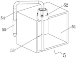
FIG. 1 is a schematic view of the overall structure of a hemming machine of the present utility model;
FIG. 2 is a cross-sectional view of a hemming machine of the present utility model;
FIG. 3 is a schematic view of a spray assembly of the edge rounding machine according to the present utility model;
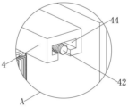
fig. 4 is an enlarged view at a in fig. 2.
In the figure: 1. a base; 11. a first chute; 2. a first servo motor; 21. a first threaded rod; 22. a first slider; 3. a moving plate; 31. a rotary table; 32. a first clamping plate; 33. a first motor; 34. an electric telescopic rod; 35. a second clamping plate; 4. a support frame; 41. a second servo motor; 42. a second threaded rod; 43. a second slider; 44. a second chute; 5. a spray assembly; 51. a water tank; 52. a water pump; 53. a water inlet pipe; 54. a water outlet pipe; 55. and (5) a water outlet spray head.
Detailed Description
The following description of the embodiments of the present utility model will be made clearly and completely with reference to the accompanying drawings, in which it is apparent that the embodiments described are only some embodiments of the present utility model, but not all embodiments. All other embodiments, which can be made by those skilled in the art based on the embodiments of the utility model without making any inventive effort, are intended to be within the scope of the utility model.
Referring to fig. 1 to 4, a rounding machine in this embodiment includes a base 1, a first servo motor 2 is fixedly mounted on one side of the base 1, an output end of the first servo motor 2 is fixedly connected with a first threaded rod 21, a first sliding block 22 is connected to the first threaded rod 21 through threads, a moving plate 3 is fixedly mounted on the first sliding block 22, a rotating table 31 is fixedly mounted on the moving plate 3, a first clamping plate 32 is fixedly mounted on a surface of the rotating table 31, a first motor 33 is fixedly mounted on a top of the moving plate 3, an output end of the first motor 33 is fixedly connected with an electric telescopic rod 34, a telescopic end of the electric telescopic rod 34 is fixedly connected with a second clamping plate 35, a support frame 4 is fixedly mounted on the base 1, a second servo motor 41 is fixedly mounted on one side of the support frame 4, a second threaded rod 42 is fixedly connected to an output end of the second servo motor 41, a second threaded rod 43 is connected to the second threaded rod 42 through threads, and a spray assembly 5 is fixedly mounted on the base 1.
The base 1 and the support frame 4 are respectively provided with a first chute 11 and a second chute 44, the first slide block 22 and the second slide block 43 are respectively in sliding connection with the base 1 and the support frame 4 through the first chute 11 and the second chute 44, and the first chute 11 and the second chute 44 respectively ensure the movement stability of the first slide block 22 and the second slide block 43.
Both ends of the first threaded rod 21 and the second threaded rod 42 are respectively connected with the base 1 and the supporting frame 4 in a rotating mode through bearings, and the first sliding block 22 and the second sliding block 43 can be respectively driven to move through rotation of the first threaded rod 21 and the second threaded rod 42.
The movable plate 3 is of a C-shaped structure, one end of the electric telescopic rod 34 is rotatably connected with the top of the movable plate 3 through a bearing, and the electric telescopic rod 34 can be driven to rotate through the first motor 33, so that the second clamping plate 35 is driven to rotate.
The spray assembly 5 comprises a water tank 51, a water pump 52 is fixedly arranged at the top of the water tank 51, a water inlet pipe 53 is fixedly communicated with a water inlet end of the water pump 52, a water outlet pipe 54 is fixedly communicated with a water outlet end of the water pump 52, a water outlet spray head 55 is fixedly communicated with one end of the water outlet pipe 54, water in the water tank 51 can be pumped out through the water pump 52, and the polished part is sprayed through the water outlet spray head 55.
One end of the water inlet pipe 53 is fixedly penetrating through the top of the water tank 51 and extends to the inside of the water tank 51, the water outlet pipe 54 is a corrugated pipe, the water outlet spray head 55 is fixedly penetrating through the bottom of the second slide block 43 and extends to the top of the second slide block 43, and the water outlet spray head 55 can be driven to move through the second slide block 43.
The working principle of the embodiment is as follows:
the glass needing round edges is placed on the first clamping plate 32, the electric telescopic rod 34 is controlled to stretch and retract, the electric telescopic rod 34 drives the second clamping plate 35 to move, the glass is clamped under the mutual matching of the first clamping plate 32 and the second clamping plate 35, the first threaded rod 21 is driven to rotate through the first servo motor 2, the first sliding block 22 moves in the first sliding groove 11, the first sliding block 22 moves to drive the movable plate 3 to move, the second servo motor 41 drives the second threaded rod 42 to move in the second sliding groove 44, then the motor and the polishing disc are driven to move, the motor drives the polishing disc to polish round edges of the glass, the electric telescopic rod 34 is driven to rotate through the first motor 33, the second clamping plate 35 is driven to rotate under the friction force of the first clamping plate 32 and the second clamping plate 35, the polishing disc is then enabled to polish round edges of the glass, water in the water tank 51 is led into the water outlet pipe 54 through the water outlet pipe 53, and the water outlet nozzle 55 is sprayed out, and the polishing disc is driven to polish edges of the glass at the same time, and dust is not produced by the polishing disc, so that the glass can be sprayed to a good environment.
It is noted that relational terms such as first and second, and the like are used solely to distinguish one entity or action from another entity or action without necessarily requiring or implying any actual such relationship or order between such entities or actions. Moreover, the terms "comprises," "comprising," or any other variation thereof, are intended to cover a non-exclusive inclusion, such that a process, method, article, or apparatus that comprises a list of elements does not include only those elements but may include other elements not expressly listed or inherent to such process, method, article, or apparatus. Without further limitation, an element defined by the phrase "comprising one … …" does not exclude the presence of other like elements in a process, method, article, or apparatus that comprises the element.
Although embodiments of the present utility model have been shown and described, it will be understood by those skilled in the art that various changes, modifications, substitutions and alterations can be made therein without departing from the principles and spirit of the utility model, the scope of which is defined in the appended claims and their equivalents.
Claims (6)
1. The utility model provides a round edge machine, including base (1), a serial communication port, one side fixed mounting of base (1) has first servo motor (2), the output fixedly connected with first threaded rod (21) of first servo motor (2), go up through threaded connection first slider (22) on first threaded rod (21), fixed mounting has movable plate (3) on first slider (22), fixed mounting has revolving stage (31) on movable plate (3), the fixed surface of revolving stage (31) installs first splint (32), the top fixed mounting of movable plate (3) has first motor (33), the output fixedly connected with electric telescopic handle (34) of first motor (33), the flexible end fixedly connected with second splint (35) of electric telescopic handle (34), one side fixed mounting of support frame (4) has second servo motor (41), the output fixedly connected with second threaded rod (42) of second servo motor (41), there is second slider (43) on second threaded rod (42) through threaded connection, fixed mounting has spray subassembly (5) on base (1).
2. A hemming machine according to claim 1 wherein: the base (1) and the support frame (4) are respectively provided with a first chute (11) and a second chute (44), and the first sliding block (22) and the second sliding block (43) are respectively in sliding connection with the base (1) and the support frame (4) through the first chute (11) and the second chute (44).
3. A hemming machine according to claim 1 wherein: both ends of the first threaded rod (21) and the second threaded rod (42) are respectively connected with the base (1) and the support frame (4) in a rotating way through bearings.
4. A hemming machine according to claim 1 wherein: the movable plate (3) is of a C-shaped structure, and one end of the electric telescopic rod (34) is rotatably connected with the top of the movable plate (3) through a bearing.
5. A hemming machine according to claim 1 wherein: the spray assembly (5) comprises a water tank (51), a water pump (52) is fixedly arranged at the top of the water tank (51), a water inlet pipe (53) is fixedly communicated with the water inlet end of the water pump (52), a water outlet pipe (54) is fixedly communicated with the water outlet end of the water pump (52), and a water outlet spray head (55) is fixedly communicated with one end of the water outlet pipe (54).
6. A hemming machine according to claim 5 wherein: one end of the water inlet pipe (53) is fixedly penetrated through the top of the water tank (51) and extends to the inside of the water tank (51), the water outlet pipe (54) is a corrugated pipe, and the water outlet nozzle (55) is fixedly penetrated through the bottom of the second sliding block (43) and extends to the top of the second sliding block (43).
Priority Applications (1)
| Application Number | Priority Date | Filing Date | Title |
|---|---|---|---|
| CN202223400837.4U CN219053876U (en) | 2022-12-19 | 2022-12-19 | Edge rounding machine |
Applications Claiming Priority (1)
| Application Number | Priority Date | Filing Date | Title |
|---|---|---|---|
| CN202223400837.4U CN219053876U (en) | 2022-12-19 | 2022-12-19 | Edge rounding machine |
Publications (1)
| Publication Number | Publication Date |
|---|---|
| CN219053876U true CN219053876U (en) | 2023-05-23 |
Family
ID=86369579
Family Applications (1)
| Application Number | Title | Priority Date | Filing Date |
|---|---|---|---|
| CN202223400837.4U Active CN219053876U (en) | 2022-12-19 | 2022-12-19 | Edge rounding machine |
Country Status (1)
| Country | Link |
|---|---|
| CN (1) | CN219053876U (en) |
-
2022
- 2022-12-19 CN CN202223400837.4U patent/CN219053876U/en active Active
Similar Documents
| Publication | Publication Date | Title |
|---|---|---|
| CN219053876U (en) | Edge rounding machine | |
| CN214393635U (en) | Grinding device is used in spare part processing | |
| CN212578287U (en) | Plastic child seat surface polishing equipment | |
| CN219617329U (en) | Curtain edging device for curtain decoration engineering | |
| CN219380291U (en) | Auxiliary limiting structure for grinding and polishing machine | |
| CN212683422U (en) | Edging device for round toughened glass | |
| CN210909327U (en) | Glass edge grinding machine | |
| CN211660707U (en) | Suction hood is used in electric automobile accessory production | |
| CN216759218U (en) | Surface grinding device is used in door plant processing | |
| CN219901749U (en) | Collecting assembly for deburring machine | |
| CN220408189U (en) | Optical lens surface polishing device | |
| CN214418354U (en) | Machining device for steel plate | |
| CN220481195U (en) | Bilateral edging device is used in toughened glass production | |
| CN219079354U (en) | Glass production cutting structure | |
| CN220127652U (en) | Drilling processing structure of marine engine frame | |
| CN220145475U (en) | Hardware fitting deckle edge grinding device | |
| CN219310861U (en) | Panel lacquer painting polisher | |
| CN219170428U (en) | Automobile sheet metal polishing device | |
| CN211516987U (en) | Polishing device with cleaning mechanism for aluminum profile production | |
| CN213196868U (en) | Glass single-side edge grinding machine | |
| CN220839566U (en) | Polishing device for limiting sleeve | |
| CN213498421U (en) | Burnishing machine for ceramic manufacture | |
| CN219131815U (en) | Polishing device for inner arc-shaped die | |
| CN219817219U (en) | Spray device capable of adjusting spray angle | |
| CN219901513U (en) | Blowing device of glass edging machine |
Legal Events
| Date | Code | Title | Description |
|---|---|---|---|
| GR01 | Patent grant | ||
| GR01 | Patent grant |