CN218964144U - Vertical lifting table milling machine - Google Patents
Vertical lifting table milling machine Download PDFInfo
- Publication number
- CN218964144U CN218964144U CN202223520515.3U CN202223520515U CN218964144U CN 218964144 U CN218964144 U CN 218964144U CN 202223520515 U CN202223520515 U CN 202223520515U CN 218964144 U CN218964144 U CN 218964144U
- Authority
- CN
- China
- Prior art keywords
- movable
- milling machine
- groove
- plate
- workbench
- Prior art date
- Legal status (The legal status is an assumption and is not a legal conclusion. Google has not performed a legal analysis and makes no representation as to the accuracy of the status listed.)
- Active
Links
Images
Classifications
-
- Y—GENERAL TAGGING OF NEW TECHNOLOGICAL DEVELOPMENTS; GENERAL TAGGING OF CROSS-SECTIONAL TECHNOLOGIES SPANNING OVER SEVERAL SECTIONS OF THE IPC; TECHNICAL SUBJECTS COVERED BY FORMER USPC CROSS-REFERENCE ART COLLECTIONS [XRACs] AND DIGESTS
- Y02—TECHNOLOGIES OR APPLICATIONS FOR MITIGATION OR ADAPTATION AGAINST CLIMATE CHANGE
- Y02P—CLIMATE CHANGE MITIGATION TECHNOLOGIES IN THE PRODUCTION OR PROCESSING OF GOODS
- Y02P70/00—Climate change mitigation technologies in the production process for final industrial or consumer products
- Y02P70/10—Greenhouse gas [GHG] capture, material saving, heat recovery or other energy efficient measures, e.g. motor control, characterised by manufacturing processes, e.g. for rolling metal or metal working
Abstract
The utility model discloses a vertical lifting table milling machine which comprises a bottom plate, a waste residue cleaning mechanism and a movable lifting mechanism, wherein the movable lifting mechanism is arranged on the bottom plate, and the waste residue cleaning mechanism is arranged on the movable lifting mechanism. The utility model belongs to the technical field of machine tools, and particularly relates to a vertical lifting table milling machine which is provided with a cleaning brush, drives a moving plate to move by pushing a screw rod and connecting a connecting rod, and is matched with a blanking groove and a waste box to clean a table surface of a working table and collect waste scraps.
Description
Technical Field
The utility model belongs to the technical field of machine tools, and particularly relates to a vertical lifting table milling machine.
Background
The vertical lifting table milling machine is a general milling machine with wide application, and is used for processing various parts by an end mill, a cylindrical mill, a saw blade mill, a disc mill, an end mill and various forming mills, and can be suitable for processing planes, inclined planes, grooves, holes and the like of various parts, and is ideal processing equipment in the die processing industry, but the milling machine can generate a large amount of residue scraps in the milling process, when the milling machine is used subsequently, a workbench needs to be cleaned, the existing milling machine lacks a scraps cleaning mechanism, manual cleaning is usually needed, the cleaning is troublesome, and the processing of subsequent workpieces is influenced by more time delay.
Disclosure of Invention
In order to solve the problems, the utility model provides the vertical lifting table milling machine which is provided with the cleaning brush, drives the moving plate to move by pushing the screw rod and connecting the connecting rod, and is matched with the blanking groove and the waste box to clean the table surface of the working table and collect the waste scraps.
In order to realize the functions, the technical scheme adopted by the utility model is as follows: a vertical lifting table milling machine comprises a bottom plate, a waste residue cleaning mechanism and a movable lifting mechanism, wherein the movable lifting mechanism is arranged on the bottom plate, and the waste residue cleaning mechanism is arranged on the movable lifting mechanism; the waste residue cleaning mechanism comprises a workbench, a screw rod, a movable plate and a blanking groove, wherein the workbench is arranged on the movable lifting mechanism, the movable groove is formed in the workbench, connecting grooves are formed in two sides of the movable groove in a penetrating mode, the screw rod is arranged on the side wall of the movable groove in a rotating mode, one end of the screw rod penetrates through the movable groove and is provided with a motor, movable blocks are movably arranged on the screw rod, connecting rods are arranged on the side wall of the movable blocks, the connecting rods penetrate through the connecting grooves, the movable plate is arranged on two groups of connecting rods, a cleaning brush is arranged on the bottom wall of the movable plate, the blanking groove is arranged at one end of the workbench, a waste box is movably arranged in the blanking groove, the motor is started to drive the screw rod to rotate, the movable blocks are driven to move by the movable blocks, the connecting rods drive the movable plate to move, cleaning brush is driven to start cleaning on the surface of the workbench, and after chips begin to be accumulated in the waste box, the waste box is pulled out from the blanking groove and cleaned.
Further, the movable lifting mechanism comprises a fixed seat, a hydraulic rod and a lifting plate, the fixed seat is arranged on the bottom plate, a milling assembly is arranged on the fixed seat, a sliding groove is formed in the side wall of the fixed seat, the hydraulic rod is arranged on the base, a plurality of groups of hydraulic rods are arranged on the hydraulic rod, and the lifting plate is arranged on the plurality of groups of hydraulic rods.
Further, the top wall of the waste box is provided with an opening.
Further, the blanking slot is arranged far away from the motor.
Preferably, the lifting plate is arranged to slide on the chute.
Preferably, the table is provided on the lifter plate.
Preferably, the motor is fixedly arranged on the side wall of the workbench.
The utility model adopts the structure to obtain the beneficial effects as follows: according to the vertical lifting table milling machine, the movable block is pushed by the screw rod through the movable plate and the blanking groove, so that the connecting rod is driven to move, the cleaning brush is convenient to clean the surface of the workbench, the waste material box is used for collecting residue scraps, the workbench is quickly cleaned, the processing efficiency of a workpiece is improved, and the lifting plate is lifted by the hydraulic rod and matched with the sliding groove, so that the stability in the lifting process can be improved.
Drawings
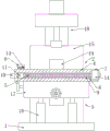
FIG. 1 is a diagram showing the overall structure of a vertical lifting milling machine according to the present utility model;
fig. 2 is a top view of a vertical lifting milling machine according to the present utility model.
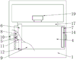
The device comprises a base plate, a waste residue cleaning mechanism, a movable lifting mechanism, a workbench, a screw rod, a moving plate, a 7, a blanking groove, a 8, a movable groove, a 9, a connecting groove, a 10, a motor, a 11, a movable block, a 12, a connecting rod, a 13, a cleaning brush, a 14, a waste box, a 15, a fixed seat, a 16, a hydraulic rod, a 17, a lifting plate, a 18, a milling component, a 19 and a chute.
Detailed Description
The following description of the embodiments of the present utility model will be made apparent and fully in view of the accompanying drawings, in which some, but not all embodiments of the utility model are shown. All other embodiments, which can be made by those skilled in the art based on the embodiments of the utility model without making any inventive effort, are intended to be within the scope of the utility model.
In the description of the present utility model, it should be noted that the directions or positional relationships indicated by the terms "center", "upper", "lower", "left", "right", "vertical", "horizontal", "inner", "outer", etc. are based on the directions or positional relationships shown in the drawings, are merely for convenience of describing the present utility model and simplifying the description, and do not indicate or imply that the devices or elements referred to must have a specific orientation, be configured and operated in a specific orientation, and thus should not be construed as limiting the present utility model. Furthermore, the terms "first," "second," and "third" are used for descriptive purposes only and are not to be construed as indicating or implying relative importance. The present utility model will be described in further detail with reference to the accompanying drawings.
As shown in fig. 1-2, the vertical lifting milling machine provided by the utility model comprises a bottom plate 1, a waste residue cleaning mechanism 2 and a movable lifting mechanism 3, wherein the movable lifting mechanism 3 is arranged on the bottom plate 1, and the waste residue cleaning mechanism 2 is arranged on the movable lifting mechanism 3; the waste residue cleaning mechanism 2 comprises a workbench 4, a screw rod 5, a movable plate 6 and a blanking groove 7, wherein the workbench 4 is arranged on the movable lifting mechanism 3, the movable groove 8 is arranged on the workbench 4, connecting grooves 9 are arranged on two sides of the movable groove 8 in a penetrating mode, the screw rod 5 is rotationally arranged on the side wall of the movable groove 8, one end of the screw rod 5 penetrates through the movable groove 8 and is provided with a motor 10, the motor 10 is fixedly arranged on the side wall of the workbench 4, a movable block 11 is movably arranged on the screw rod 5, a connecting rod 12 is arranged on the side wall of the movable block 11, the connecting rod 12 penetrates through the connecting grooves 9, the movable plate 6 is arranged on two groups of connecting rods 12, a cleaning brush 13 is arranged on the bottom wall of the movable plate 6, the blanking groove 7 is arranged at one end of the workbench 4, the blanking groove 7 is arranged away from the motor 10, a waste material box 14 is movably arranged in the blanking groove 7, the top wall of the waste material box 14 is arranged in an opening mode, the movable lifting mechanism 3 comprises a fixed seat 15, a hydraulic rod 16 and a lifting plate 17, the fixed seat 15 is arranged on the bottom plate 1, a milling component 18 is arranged on the side wall of the fixed seat 15, a sliding groove 19 is arranged on the fixed seat 16, a plurality of groups of hydraulic rods 16 are arranged on the base, the lifting plate 17 are arranged on the lifting plate 17, a plurality of groups of hydraulic rod 16 are arranged on the lifting plate 17, the lifting plate 17 are arranged on the sliding groove 17, and the lifting plate is arranged on the lifting plate 4.
When the automatic cleaning device is specifically used, the motor 10 is started to drive the screw rod 5 to rotate, the screw rod 5 pushes the movable block 11 to move, the movable block 11 drives the connecting rod 12 to move, the connecting rod 12 drives the movable plate 6 to move, the movable plate 6 drives the cleaning brush 13 to move to start cleaning the surface of the workbench 4, the cleaning brush 13 pushes scraps to the upper part of the blanking groove 7, the scraps fall into the scraps box 14, and after the scraps begin to be accumulated in the scraps box 14, the scraps box 14 is pulled out from the blanking groove 7 and cleaned.
The utility model and its embodiments have been described above with no limitation, and the actual construction is not limited to the embodiments of the utility model as shown in the drawings. In summary, if one of ordinary skill in the art is informed by this disclosure, a structural manner and an embodiment similar to the technical solution should not be creatively devised without departing from the gist of the present utility model.
Claims (7)
1. A vertical lifting table milling machine is characterized in that: the device comprises a bottom plate, a waste residue cleaning mechanism and a movable lifting mechanism, wherein the movable lifting mechanism is arranged on the bottom plate; the waste residue cleaning mechanism comprises a workbench, a screw rod, a movable plate and a blanking groove, wherein the workbench is arranged on the movable lifting mechanism, a movable groove is formed in the workbench, connecting grooves are formed in two sides of the movable groove in a penetrating mode, the screw rod is rotationally arranged on the side wall of the movable groove, one end of the screw rod penetrates through the movable groove and is provided with a motor, a movable block is movably arranged on the screw rod, a connecting rod is arranged on the side wall of the movable block, the connecting rod penetrates through the connecting groove, the movable plate is arranged on the two groups of the connecting rods, a cleaning brush is arranged on the bottom wall of the movable plate, the blanking groove is arranged at one end of the workbench, and a waste box is movably arranged in the blanking groove.
2. A vertical lift milling machine as claimed in claim 1 wherein: the movable lifting mechanism comprises a fixed seat, a hydraulic rod and a lifting plate, wherein the fixed seat is arranged on the bottom plate, a milling assembly is arranged on the fixed seat, a sliding groove is formed in the side wall of the fixed seat, the hydraulic rod is arranged on the base, a plurality of groups of hydraulic rods are arranged, and the lifting plate is arranged on the plurality of groups of hydraulic rods.
3. A vertical lift milling machine as claimed in claim 2 wherein: the roof of waste material box is the opening setting.
4. A vertical lift milling machine as claimed in claim 3 wherein: the blanking groove is arranged far away from the motor.
5. The vertical lift milling machine of claim 4 wherein: the lifting plate is arranged on the sliding groove in a sliding way.
6. A vertical lift milling machine as claimed in claim 5 wherein: the workbench is arranged on the lifting plate.
7. The vertical lift milling machine of claim 6 wherein: the motor is fixedly arranged on the side wall of the workbench.
Priority Applications (1)
| Application Number | Priority Date | Filing Date | Title |
|---|---|---|---|
| CN202223520515.3U CN218964144U (en) | 2022-12-28 | 2022-12-28 | Vertical lifting table milling machine |
Applications Claiming Priority (1)
| Application Number | Priority Date | Filing Date | Title |
|---|---|---|---|
| CN202223520515.3U CN218964144U (en) | 2022-12-28 | 2022-12-28 | Vertical lifting table milling machine |
Publications (1)
| Publication Number | Publication Date |
|---|---|
| CN218964144U true CN218964144U (en) | 2023-05-05 |
Family
ID=86152306
Family Applications (1)
| Application Number | Title | Priority Date | Filing Date |
|---|---|---|---|
| CN202223520515.3U Active CN218964144U (en) | 2022-12-28 | 2022-12-28 | Vertical lifting table milling machine |
Country Status (1)
| Country | Link |
|---|---|
| CN (1) | CN218964144U (en) |
-
2022
- 2022-12-28 CN CN202223520515.3U patent/CN218964144U/en active Active
Similar Documents
| Publication | Publication Date | Title |
|---|---|---|
| CN111070025B (en) | Grinding machine tool for processing inner spherical surface | |
| CN210189209U (en) | A sweeps cleaning device for drilling machine | |
| CN218964144U (en) | Vertical lifting table milling machine | |
| CN219053766U (en) | Horizontal machining center | |
| CN212071261U (en) | Based on filter equipment for digit control machine tool | |
| CN214393427U (en) | Drilling machine convenient to clean | |
| CN213561377U (en) | Automatic change numerical control processingequipment | |
| CN213615401U (en) | Drilling machine tool convenient to collect waste material | |
| CN210360535U (en) | Waste cleaning device for radial drilling machine | |
| CN211249131U (en) | Lifting platform of milling machine | |
| CN114102783A (en) | Solid wood door plate production and processing equipment and use method thereof | |
| CN210651093U (en) | Double-end corner sawing machine | |
| CN219900516U (en) | Milling device for gear machining and manufacturing | |
| CN218745114U (en) | Precise numerical control planer type milling machine capable of cutting at high speed | |
| CN213944921U (en) | Automatic clear up numerical control lathe anchor clamps of sweeps | |
| CN218983990U (en) | Tool box production tool | |
| CN220240169U (en) | Special-shaped aluminum plate cutting machine | |
| CN217393869U (en) | C shaped steel cutting device convenient to garbage collection | |
| CN219188733U (en) | High-precision numerical control drilling equipment | |
| CN210210934U (en) | Aerated brick cutting machine | |
| CN218396910U (en) | Machine tool guide rail and screw rod adjusting device | |
| CN212761193U (en) | Novel drilling machine | |
| CN215512366U (en) | Diamond saw blade cold press molding equipment | |
| CN217166579U (en) | Boring machine for metal plate | |
| CN214134043U (en) | Drilling machine with dust removal system |
Legal Events
| Date | Code | Title | Description |
|---|---|---|---|
| GR01 | Patent grant | ||
| GR01 | Patent grant |