CN218946486U - Plate shearing machine feeder - Google Patents
Plate shearing machine feeder Download PDFInfo
- Publication number
- CN218946486U CN218946486U CN202222952459.4U CN202222952459U CN218946486U CN 218946486 U CN218946486 U CN 218946486U CN 202222952459 U CN202222952459 U CN 202222952459U CN 218946486 U CN218946486 U CN 218946486U
- Authority
- CN
- China
- Prior art keywords
- shearing machine
- limiting
- side wall
- supporting base
- plate shearing
- Prior art date
- Legal status (The legal status is an assumption and is not a legal conclusion. Google has not performed a legal analysis and makes no representation as to the accuracy of the status listed.)
- Active
Links
Images


Classifications
-
- Y—GENERAL TAGGING OF NEW TECHNOLOGICAL DEVELOPMENTS; GENERAL TAGGING OF CROSS-SECTIONAL TECHNOLOGIES SPANNING OVER SEVERAL SECTIONS OF THE IPC; TECHNICAL SUBJECTS COVERED BY FORMER USPC CROSS-REFERENCE ART COLLECTIONS [XRACs] AND DIGESTS
- Y02—TECHNOLOGIES OR APPLICATIONS FOR MITIGATION OR ADAPTATION AGAINST CLIMATE CHANGE
- Y02P—CLIMATE CHANGE MITIGATION TECHNOLOGIES IN THE PRODUCTION OR PROCESSING OF GOODS
- Y02P70/00—Climate change mitigation technologies in the production process for final industrial or consumer products
- Y02P70/10—Greenhouse gas [GHG] capture, material saving, heat recovery or other energy efficient measures, e.g. motor control, characterised by manufacturing processes, e.g. for rolling metal or metal working
Abstract
The utility model discloses a plate shearing machine feeder which comprises a supporting base, wherein two symmetrically arranged connecting bases are fixedly connected to the side wall of the supporting base, plate shearing machine bodies are arranged on the two connecting bases, scissors are arranged on one side, close to the supporting base, of the plate shearing machine bodies, corresponding grooves are formed in the side wall, close to the scissors, of the supporting base, two symmetrically arranged limiting frames are fixedly connected to the side wall, close to the scissors, of the supporting base, and limiting mechanisms used for limiting and guiding plates in the conveying and feeding process are arranged in the limiting frames. According to the utility model, through the structures such as the sliding groove, the traction frame, the limiting frame and the like, the metal plate is pulled to move forwards through the traction frame, so that the metal plate is prevented from moving relatively with the track and the propelling device in the moving process, and meanwhile, the limiting frame and the limiting roller are matched to limit the metal plate in the feeding process, so that the stability and the cutting accuracy of the metal plate in the cutting process are ensured.
Description
Technical Field
The utility model relates to the technical field of plate shearing machines, in particular to a plate shearing machine feeder.
Background
The mechanical plate shearing machine adopts a clutch structure in a resistance key form and open gear transmission, adopts more advanced electric appliances (foot switch and manual switch) to operate, and has low noise and convenient operation and maintenance. And the full-steel welding structure is adopted, the structure is simple, the operation is simple and convenient, the appearance is attractive, and the energy consumption is low. The method is widely used in metallurgy, light industry, machinery, hardware, motors, electric appliances, automobile maintenance, hardware manufacturing and other metal sheet processing industries.
When shearing machine cuts the metal sheet, the material loading in-process of metal sheet, need place the metal sheet more on the board advances the track, realize the feeding process of metal sheet in shearing in-process through the propulsive mode afterwards, this kind of mode is when using, impel the metal sheet to the cutting position through advancing device, the propulsive in-process is because the metal sheet slides on shearing platform, consequently can influence the metal sheet direction of feeding at propulsive in-process, cutting position and cutting accuracy all can cause the influence, simultaneously advancing device appear easily at the in-process that removes with the relative movement between the metal sheet, consequently lead to the phenomenon emergence that cutting dimensional accuracy reduces.
Disclosure of Invention
The utility model aims to solve the defects in the prior art and provides a plate shearing machine feeder.
In order to achieve the above purpose, the present utility model adopts the following technical scheme:
the utility model provides a plate shearing machine feeder, includes the support base, the lateral wall fixedly connected with of support base two symmetry sets up connect the base, two be equipped with the plate shearing machine body on the connection base, one side that the plate shearing machine body is close to the support base is equipped with the scissors, the corresponding groove has been seted up to one side lateral wall that the support base is close to the scissors, one side lateral wall fixedly connected with that the support base is close to the scissors two symmetry sets up spacing, be equipped with the stop gear who is used for carrying feeding in-process spacing and direction to panel in the spacing, two symmetry sets up the sliding tray to the preceding lateral wall of support base and scissors, sliding connection has the traction frame in the sliding tray, set up the adjustment tank in the traction frame, be equipped with a plurality of equidistant supporting shoe that set up in the adjustment tank, be equipped with in the traction frame and be used for supporting and the installation mechanism to the supporting shoe, the lateral wall that the support base is kept away from spacing one side is equipped with and is used for removing in-process driven actuating mechanism to the traction frame.
Preferably, the limiting mechanism comprises a mounting groove formed in the side wall opposite to the two limiting frames, and a plurality of limiting rollers arranged at equal intervals are rotationally connected in the mounting groove.
Preferably, the mounting mechanism comprises two symmetrically arranged telescopic rods fixedly connected to opposite side walls of the supporting block and the adjusting groove, mounting bolts are connected to telescopic ends of the telescopic rods in a threaded mode, a plurality of equidistant mounting grooves are formed in opposite side walls of the traction frame and the sliding groove, and the mounting bolts penetrate through the mounting grooves.
Preferably, the driving mechanism comprises a driving motor fixedly connected to the side wall of the supporting base, which is far away from the limiting frame, an output shaft of the driving motor is fixedly connected with a driving gear, a rack is fixedly connected to the side wall of the traction frame, which is opposite to the sliding groove, and the driving gear is matched with the rack.
Preferably, two symmetrically arranged clamping grooves are formed in the inner side wall of the sliding groove, clamping blocks are fixedly connected to the side walls of the two sides of the traction frame, and the clamping blocks are slidably connected in the clamping grooves.
Preferably, the lateral wall of one side of supporting shoe far away from the traction frame is equipped with the laminating board, the lateral wall of one side of laminating board far away from the supporting shoe is equipped with the anti-skidding line.
Compared with the prior art, the utility model has the beneficial effects that:
1. through setting up sliding tray, traction frame and limit frame isotructure, pull the metal sheet antedisplacement through traction frame, avoid the metal sheet to take place relative movement between removal in-process and track and advancing device, cooperation limit frame and spacing gyro wheel carry out spacingly to the metal sheet feeding in-process simultaneously, ensure that the metal sheet is in the maintenance stability and the cutting accuracy of cutting in-process.
2. Through setting up structures such as supporting shoe, adjustment tank, telescopic link and mounting groove, through the contact at supporting shoe and metal sheet cutting position, keep cutting position inconvenient to through the cooperation of supporting shoe scissors, realize supporting tight cutting on the upper and lower direction of metal sheet in the cutting process, avoid the relative movement to appear in the cutting process metal sheet, cooperation mounting groove and mounting bolt can realize the regulation of supporting shoe at adjustment tank mounted position simultaneously, correspond the different cutting size of metal sheet.
Drawings
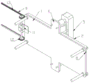
Fig. 1 is a schematic diagram of a front view and a three-dimensional structure of a feeder of a plate shearing machine according to the present utility model;
fig. 2 is a schematic bottom perspective view of a feeder of a plate shearing machine according to the present utility model;
fig. 3 is a schematic diagram of a cross-sectional structure of a traction frame of a feeder of a plate shearing machine according to the present utility model.
In the figure: the device comprises a supporting base 1, a limiting frame 2, a limiting roller 3, a connecting base 4, a plate shearing machine body 5, scissors 6, corresponding grooves 7, sliding grooves 8, a traction frame 9, an adjusting groove 10, a driving motor 11, a driving gear 12, a rack 13, a supporting block 14, a telescopic rod 15 and a mounting groove 16.
Detailed Description
In order that the above objects, features and advantages of the utility model will be readily understood, a more particular description of the utility model will be rendered by reference to the appended drawings. In the following description, numerous specific details are set forth in order to provide a thorough understanding of the present utility model. The utility model may be embodied in many other forms than described herein and similarly modified by those skilled in the art without departing from the spirit or scope of the utility model, which is therefore not limited to the specific embodiments disclosed below.
Referring to fig. 1-3, a plate shearing machine feeder, including supporting base 1, the lateral wall fixedly connected with of supporting base 1 connects base 4 that two symmetries set up, be equipped with plate shearing machine body 5 on two connection bases 4, one side that plate shearing machine body 5 is close to supporting base 1 is equipped with scissors 6, corresponding groove 7 has been seted up to one side lateral wall that supporting base 1 is close to scissors 6, one side lateral wall fixedly connected with of supporting base 1 is close to scissors 6 two spacing 2 that the symmetry set up, be equipped with in the spacing 2 and be used for carrying the spacing and guiding in the feeding process to panel, stop gear is including seting up the mounting groove at two spacing 2 opposite lateral walls, the mounting groove rotation is connected with a plurality of spacing gyro wheels 3 of equidistant setting.
Two symmetrically-arranged sliding grooves 8 are formed in the side walls of the supporting base 1 and the scissors 6, a traction frame 9 is connected in the sliding grooves 8 in a sliding mode, an adjusting groove 10 is formed in the traction frame 9, a plurality of supporting blocks 14 which are arranged at equal intervals are arranged in the adjusting groove 10, an attaching plate is arranged on the side wall of one side, far away from the traction frame 9, of the supporting blocks 14, and anti-skid patterns are formed on the side wall of one side, far away from the supporting blocks 14, of the attaching plate;
the traction frame 9 is internally provided with a mounting mechanism for supporting and mounting the supporting block 14, the mounting mechanism comprises two symmetrically arranged telescopic rods 15 fixedly connected to opposite side walls of the supporting block 14 and the adjusting groove 10, telescopic ends of the telescopic rods 15 are in threaded connection with mounting bolts, opposite side walls of the traction frame 9 and the sliding groove 8 are provided with a plurality of mounting grooves 16 which are arranged at equal intervals, and the mounting bolts penetrate through the mounting grooves 16.
The lateral wall that spacing 2 one side was kept away from to support base 1 is equipped with and is used for keeping away from spacing 2 one side in-process driven actuating mechanism to traction frame 9, actuating mechanism includes fixed connection at the driving motor 11 that support base 1 kept away from spacing 2 one side lateral wall, driving motor 11's output shaft fixedly connected with drive gear 12, traction frame 9 and the relative lateral wall fixedly connected with rack 13 of sliding tray 8, drive gear 12 cooperatees with rack 13, the joint groove that two symmetries set up has been seted up to the inside wall of sliding tray 8, the equal fixedly connected with joint piece of both sides lateral wall of traction frame 9, joint piece sliding connection is in the joint inslot.
When the utility model is used, as shown in fig. 1-3, firstly, a metal plate is placed on two traction frames 9 and props against the upper end faces of supporting blocks 14, fixing of the supporting blocks 14 and supporting of the metal plate can be realized by installing bolts in telescopic rods 15 and installing grooves 16, the supporting blocks 14 are matched with protective patterns of the bonding plates on the supporting blocks 14, relative movement between the supporting blocks 14 and the metal plate in the feeding process can be avoided, meanwhile, the installing grooves 16 are matched with the supporting blocks 14 to realize adjustment and regulation of the installation distance between the supporting blocks 14, the output shaft of a driving motor 11 drives driving gears 12 at two ends to be meshed with racks 13 below the traction frames 9 in the feeding process, simultaneous movement of the traction frames 9 at two sides can be realized by power transmission between the driving gears 12 and the racks 13, a plurality of supporting blocks 14 correspond to the scissors 6, the metal plate props against the supporting blocks 14 in the cutting process, the supporting blocks 14 are matched with the telescopic rods 15 to keep clamping the metal plate all the time in the pressing shearing process, the edge of the metal plate and the limiting frames 2 in the feeding process can be used for preventing relative movement of the limiting rollers 9 in the feeding process.
The foregoing is only a preferred embodiment of the present utility model, but the scope of the present utility model is not limited thereto, and any person skilled in the art, who is within the scope of the present utility model, should make equivalent substitutions or modifications according to the technical scheme of the present utility model and the inventive concept thereof, and should be covered by the scope of the present utility model.
Claims (6)
1. A plate shearing machine feeder, which comprises a supporting base (1) and is characterized in that, the side wall of the supporting base (1) is fixedly connected with two symmetrically arranged connecting bases (4), the two connecting bases (4) are provided with plate shearing machine bodies (5), a scissors (6) is arranged on one side of the plate shearing machine body (5) close to the supporting base (1), a corresponding groove (7) is formed on the side wall of the supporting base (1) close to the scissors (6), two limit frames (2) which are symmetrically arranged are fixedly connected with the side wall of one side of the supporting base (1) close to the scissors (6), a limiting mechanism for limiting and guiding the plate in the process of conveying and feeding is arranged in the limiting frame (2), two symmetrically arranged sliding grooves (8) are formed on the side walls of the supporting base (1) and the scissors (6), a traction frame (9) is connected in a sliding way in the sliding groove (8), an adjusting groove (10) is arranged in the traction frame (9), a plurality of supporting blocks (14) which are arranged at equal intervals are arranged in the adjusting groove (10), the traction frame (9) is internally provided with a mounting mechanism for supporting and mounting the supporting block (14), the side wall of one side of the supporting base (1) far away from the limiting frame (2) is provided with a driving mechanism for driving the traction frame (9) in the moving process.
2. The plate shearing machine feeder according to claim 1, wherein the limiting mechanism comprises a mounting groove formed in the opposite side walls of the two limiting frames (2), and a plurality of limiting rollers (3) arranged at equal intervals are rotationally connected in the mounting groove.
3. The plate shearing machine feeder according to claim 2, wherein the mounting mechanism comprises two symmetrically arranged telescopic rods (15) fixedly connected to opposite side walls of the supporting block (14) and the adjusting groove (10), telescopic ends of the telescopic rods (15) are in threaded connection with mounting bolts, a plurality of mounting grooves (16) which are arranged at equal intervals are formed in opposite side walls of the traction frame (9) and the sliding groove (8), and the mounting bolts penetrate through the mounting grooves (16).
4. A plate shearing machine feeder according to claim 3, characterized in that the driving mechanism comprises a driving motor (11) fixedly connected to the side wall of the supporting base (1) far away from the limiting frame (2), an output shaft of the driving motor (11) is fixedly connected with a driving gear (12), the side wall of the traction frame (9) opposite to the sliding groove (8) is fixedly connected with a rack (13), and the driving gear (12) is matched with the rack (13).
5. The plate shearing machine feeder according to claim 4, wherein two symmetrically arranged clamping grooves are formed in the inner side wall of the sliding groove (8), clamping blocks are fixedly connected to the side walls of the two sides of the traction frame (9), and the clamping blocks are slidably connected in the clamping grooves.
6. A plate shearing machine feeder as defined in claim 5, wherein a side wall of said supporting block (14) away from said traction frame (9) is provided with an attaching plate, and a side wall of said attaching plate away from said supporting block (14) is provided with anti-slip patterns.
Priority Applications (1)
| Application Number | Priority Date | Filing Date | Title |
|---|---|---|---|
| CN202222952459.4U CN218946486U (en) | 2022-11-04 | 2022-11-04 | Plate shearing machine feeder |
Applications Claiming Priority (1)
| Application Number | Priority Date | Filing Date | Title |
|---|---|---|---|
| CN202222952459.4U CN218946486U (en) | 2022-11-04 | 2022-11-04 | Plate shearing machine feeder |
Publications (1)
| Publication Number | Publication Date |
|---|---|
| CN218946486U true CN218946486U (en) | 2023-05-02 |
Family
ID=86111392
Family Applications (1)
| Application Number | Title | Priority Date | Filing Date |
|---|---|---|---|
| CN202222952459.4U Active CN218946486U (en) | 2022-11-04 | 2022-11-04 | Plate shearing machine feeder |
Country Status (1)
| Country | Link |
|---|---|
| CN (1) | CN218946486U (en) |
-
2022
- 2022-11-04 CN CN202222952459.4U patent/CN218946486U/en active Active
Similar Documents
| Publication | Publication Date | Title |
|---|---|---|
| CN102528939A (en) | Full-automatic longitudinal and transverse multi-cutting-head combined edge trimmer | |
| CN210732845U (en) | Plate cutting device and large plate cutting machine comprising same | |
| CN201071909Y (en) | Transmission device of plate feeding apparatus | |
| CN209522285U (en) | A kind of plate transfer device | |
| CN218946486U (en) | Plate shearing machine feeder | |
| CN101941251A (en) | Feeding structure for stone cutter | |
| CN220098402U (en) | Stock bin lifting mechanism | |
| CN111070394B (en) | Automatic feeding and napping device for composite board processing | |
| CN113060500A (en) | Roller for roller conveyor with firm structure | |
| CN210029269U (en) | PCB board loading machine | |
| CN202448242U (en) | Automatic combined edge trimmer with multiple longitudinal-transverse cutting heads | |
| CN111002630A (en) | Production device of combined packaging carton | |
| CN206622536U (en) | A kind of metal board beader feed mechanism | |
| CN213224781U (en) | Numerical control laser cutting machine convenient to unloading | |
| CN114210794A (en) | Rolling forming machine | |
| CN210475666U (en) | Plate cutting device for machining low-voltage switch cabinet | |
| CN207120196U (en) | One kind upset platform | |
| CN206543829U (en) | Mobile die-filling platform | |
| CN220259739U (en) | Traction and sawing structure of traction machine | |
| CN218873922U (en) | Efficient cutting device is used in preparation of aluminium template | |
| CN219884870U (en) | Mold core conveyor for hollow building blocks | |
| CN216969745U (en) | Panel conveyor for machining workshop | |
| CN220576139U (en) | Cutting device is used in chemical industry equipment production | |
| CN220413183U (en) | Toughened glass production is with unloading platform | |
| CN217476678U (en) | Hot forming machine mould table capable of quickly locking mould |
Legal Events
| Date | Code | Title | Description |
|---|---|---|---|
| GR01 | Patent grant | ||
| GR01 | Patent grant |