CN218926819U - Gear pump bearing press - Google Patents
Gear pump bearing press Download PDFInfo
- Publication number
- CN218926819U CN218926819U CN202223499302.7U CN202223499302U CN218926819U CN 218926819 U CN218926819 U CN 218926819U CN 202223499302 U CN202223499302 U CN 202223499302U CN 218926819 U CN218926819 U CN 218926819U
- Authority
- CN
- China
- Prior art keywords
- bearing
- top surface
- groove
- gear pump
- limiting
- Prior art date
- Legal status (The legal status is an assumption and is not a legal conclusion. Google has not performed a legal analysis and makes no representation as to the accuracy of the status listed.)
- Active
Links
Images


Abstract
The utility model discloses a gear pump bearing press, which has the technical scheme that: the device comprises a base, wherein a rotating groove is formed in the top surface of the base, a supporting frame is fixedly arranged on the top surface of the base, a mounting plate is fixedly arranged on one side of the supporting frame, and a placing table is arranged in the rotating groove; limiting component, limiting component sets up place the top surface of platform for limiting bearing places the position, through setting up limiting component, first electric putter's flexible end can establish with the interior ring movable sleeve of bearing, first electric putter's flexible end makes the bearing inner ring be in same centre of a circle with the outer loop, inner ring position skew when having avoided the gland, effectively avoid roller bearing inner ring toper, the problem that the manual work placed and can lead to the position to appear the skew improves the gland efficiency of bearing, through setting up second electric putter, the second electric putter can be with placing in the ejecting base of bearing of stopper top surface, the staff of being convenient for takes the bearing that the gland is good.
Description
Technical Field
The utility model relates to the technical field of bearing capping machines, in particular to a gear pump bearing press.
Background
According to publication No.: the Chinese patent of CN215762858U, a bearing capping machine, including workstation, support cylinder and clamp plate, the support is installed to the top of workstation, the cylinder is installed to one side of support below, the clamp plate is installed to the below of cylinder, cover falling device is installed to the opposite side below the support, place the platform is installed to the top of workstation, the inside of workstation is provided with inwards sunken spout, the inside of spout is provided with the slider, the top of slider is connected with the bottom of cell body; according to the utility model, the rotating mechanism is arranged in the workbench, and the placing plate can be driven to rotate by utilizing the mutual matching of the first bevel gear, the second bevel gear, the sliding chute, the sliding block and the first servo motor of the rotating mechanism.
However, a bearing capping machine as described above still has some drawbacks, such as: the top of workstation is installed and is placed the platform, the inside of workstation is provided with the inwards sunken spout, and above-mentioned scheme has following shortcoming: because the large, medium displacement, medium, high pressure and high pressure gear pumps use roller bearings with large bearing capacity per unit volume, but the roller bearings are manually placed on a placing table, the inner rings of some bearings are tapered, the manual placement can cause position deviation, and the gland of the bearings is inconvenient.
Disclosure of Invention
Aiming at the defects of the prior art, the utility model provides a gear pump bearing press, which solves the problems that the roller bearings with large bearing capacity per unit volume are used by large, medium, high and high-pressure gear pumps, but the roller bearings are manually placed on a placing table, the inner rings of some bearings are tapered, the manual placement can cause position deviation, and the gland of the bearings is inconvenient.
The technical aim of the utility model is realized by the following technical scheme:
a gear pump bearing press comprising: the base, the top surface of base has offered the rotary groove, the top surface of base is fixedly mounted with the support frame, one side of the said support frame is fixedly mounted with the mounting panel, the inside of the said rotary groove has placed the platform; and the limiting assembly is arranged on the top surface of the placing table and used for limiting the placing position of the bearing.
Through adopting above-mentioned technical scheme, through setting up spacing subassembly, effectively avoid roller bearing inner ring toper, the manual work is placed and can lead to the problem that the skew appears in the position to improve the gland efficiency of bearing.
Preferably, the limiting assembly includes: the limiting grooves are formed in the top surface of the placing table, limiting blocks are arranged in the limiting grooves, telescopic grooves are formed in the top surfaces of the limiting blocks, and first electric push rods are fixedly arranged in the telescopic grooves.
Through adopting above-mentioned technical scheme, through setting up first electric putter, first electric putter's flexible end can establish with the interior ring movable sleeve of bearing, and first electric putter's flexible end makes bearing inner ring and outer loop be in same centre of a circle, inner ring position skew when having avoided the gland.
Preferably, the bottom surface of mounting panel fixed mounting has the claw pole that presss from both sides, the bottom surface fixed mounting of mounting panel has the pole of placing, the bottom surface fixed mounting of mounting panel has the cylinder, the telescopic end fixed mounting of cylinder has the clamp plate.
Through adopting above-mentioned technical scheme, through setting up the clamp claw pole, but clamping jaw bearing places in the inside of spacing groove, through setting up the pole of placing, can place the gland in the top surface of bearing, through setting up the cylinder, the cylinder can drive clamp plate punching press gland.
Preferably, the second electric push rod is fixedly arranged on the inner bottom surface of the limiting groove, the telescopic end of the second electric push rod is fixedly arranged on the bottom surface of the limiting block, the sliding blocks are respectively and fixedly arranged on the left side and the right side of the limiting block, the sliding grooves are respectively formed in the left side and the right side of the inner portion of the limiting groove, and the sliding blocks are movably sleeved with the sliding grooves.
Through adopting above-mentioned technical scheme, through setting up the second electric putter, the second electric putter can be with placing in the ejecting base of bearing of stopper top surface, and the staff of being convenient for takes the well bearing of gland.
Preferably, a driving groove is formed in the inner bottom surface of the rotating groove, and a driving motor is fixedly mounted on the inner bottom surface of the driving groove.
Through adopting above-mentioned technical scheme, through setting up driving motor, driving motor can drive and place the platform rotation, can realize gland continuity of work, improves gland efficiency.
Preferably, a turntable is arranged in the rotating groove, the bottom surface of the turntable is fixedly arranged at the output end of the driving motor, and the top surface of the turntable is fixedly arranged at the bottom surface of the placing table.
Through adopting above-mentioned technical scheme, through setting up the carousel, the carousel improves and drives to place the platform from pivoted area of atress, improves driving motor's efficiency.
In summary, the utility model has the following advantages:
through setting up spacing subassembly, first electric putter's flexible end can establish with the interior ring movable sleeve of bearing, and first electric putter's flexible end makes the bearing inner loop be in same centre of a circle with the outer loop, and the inner loop position skew has effectively avoided the roller bearing inner loop toper when having avoided the gland, and the manual work is placed and can be led to the problem that the position skew appears and improve the gland efficiency of bearing.
Through setting up the second electric putter, the second electric putter can be with placing in the ejecting base of bearing of stopper top surface, and the staff of being convenient for takes the well bearing of gland, and the carousel improves and drives and place the platform from pivoted area of force, improves driving motor's efficiency.
Drawings
FIG. 1 is a schematic perspective view of the present utility model;
FIG. 2 is a schematic view of a split construction of the present utility model;
FIG. 3 is a schematic view of a stopper according to the present utility model;
fig. 4 is a schematic view of the structure of the driving slot of the present utility model.
Reference numerals: 1. a base; 2. a rotating groove; 3. a support frame; 4. a mounting plate; 5. a placement table; 6. a limit groove; 7. a limiting block; 8. a telescopic slot; 9. a first electric push rod; 10. a clamping claw rod; 11. placing a rod; 12. a cylinder; 13. a pressing plate; 14. a second electric push rod; 15. a sliding block; 16. a sliding groove; 17. a driving groove; 18. a driving motor; 19. a turntable.
Detailed Description
The following description of the embodiments of the present utility model will be made clearly and completely with reference to the accompanying drawings, in which it is apparent that the embodiments described are only some embodiments of the present utility model, but not all embodiments. All other embodiments, which can be made by those skilled in the art based on the embodiments of the utility model without making any inventive effort, are intended to be within the scope of the utility model.
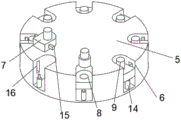
Referring to fig. 1, fig. 2 and fig. 3, a gear pump bearing press, which comprises a base 1, the rotary tank 2 has been seted up to the top surface of base 1, the top surface fixed mounting of base 1 has support frame 3, one side fixed mounting of support frame 3 has mounting panel 4, the inside of rotary tank 2 is provided with places platform 5, the top surface of placing platform 5 is provided with spacing subassembly for the position that the restriction bearing was placed, through setting up spacing subassembly, effectively avoid the roller bearing inner ring toper, the problem that the manual work placed and can lead to the position to appear the skew improves the gland efficiency of bearing, spacing subassembly includes a plurality of spacing groove 6, the top surface at placing platform 5 is all seted up to a plurality of spacing groove 6, the inside of spacing groove 6 is provided with stopper 7, expansion groove 8 has been seted up to the top surface of stopper 7, the inside fixed mounting of expansion groove 8 has first electric putter 9, first electric putter 9 is for having the structure and does not do not make here, through setting up first electric putter 9, the flexible end of first electric putter 9 can be set up with the inner ring movable sleeve of bearing, the gland has been made the inner ring of bearing inner ring and outer ring is in same centre of circle position when the gland has been avoided the skew.
Referring to fig. 2 and 3, the bottom surface fixed mounting of mounting panel 4 has clamp claw pole 10, the bottom surface fixed mounting of mounting panel 4 has placing bar 11, the bottom surface fixed mounting of mounting panel 4 has cylinder 12, cylinder 12 is for having the structure and do not do nothing here, the telescopic end fixed mounting of cylinder 12 has clamp plate 13, through setting up clamp claw pole 10, but clamping jaw bearing places in the inside of spacing groove 6, through setting up placing bar 11, can place the gland in the top surface of bearing, through setting up cylinder 12, cylinder 12 can drive clamp plate 13 punching press gland, the inside bottom surface fixed mounting of spacing groove 6 has second electric putter 14, second electric putter 14 is the bottom surface fixed mounting of existing structure here for not going forward, the flexible end of second electric putter 14 and the bottom surface fixed mounting of stopper 7, the left and right sides of stopper 7 respectively fixed mounting has sliding block 15, sliding groove 16 has been seted up respectively to the inside left and right sides of spacing groove 6, sliding block 15 and sliding groove 16 movable sleeve are established, through setting up second electric putter 14, second electric putter 14 can be with placing in the bearing base 1 of stopper 7 top surface, the well bearing of staff takes.
Referring to fig. 2 and 4, the driving groove 17 is formed in the inner bottom surface of the rotating groove 2, the driving motor 18 is fixedly mounted on the inner bottom surface of the driving groove 17, the driving motor 18 is of an existing structure, and is not described in detail herein, by means of the driving motor 18, the driving motor 18 can drive the placing table 5 to rotate, so that the continuity of gland operation can be achieved, the gland efficiency is improved, the turntable 19 is arranged in the rotating groove 2, the bottom surface of the turntable 19 is fixedly mounted with the output end of the driving motor 18, the top surface of the turntable 19 is fixedly mounted with the bottom surface of the placing table 5, and the turntable 19 is arranged to improve the stress area for driving the placing table 5 to rotate and the efficiency of the driving motor 18.
Working principle: referring to fig. 1-4, when in use, a worker can place a bearing to be capped in the working range of the gripper bar 10, the gripper bar 10 places the bearing to be capped in the inside of the limit groove 6, so that the telescopic end of the first electric push rod 9 is movably sleeved with the inner ring of the bearing, the telescopic end of the first electric push rod 9 enables the inner ring of the bearing to be positioned at the same center of a circle with the outer ring, the inner ring position deviation during capping is avoided, the driving motor 18 is started, the gripper bar 10 continues to place the bearing in the inside of the limit groove 6, the driving motor 18 drives the placing table 5 to rotate, when the bearing to be capped rotates to the position right below the placing bar 11, the placing bar 11 places the capping on the top surface of the bearing, the bearing continues to rotate along with the placing table 5, when the bearing is positioned below the air cylinder 12, the air cylinder 12 drives the pressing plate 13 to punch the bearing, the capping work is completed, the placing table 5 continues to rotate, and in the rotating process, the second electric push rod 14 drives the limiting block 7 to rise, when the bearing is positioned on the top surface of the placing table 5, the first electric push rod 9 contracts, and the worker can take down the bearing after capping.
Although embodiments of the present utility model have been shown and described, it will be understood by those skilled in the art that various changes, modifications, substitutions and alterations can be made therein without departing from the principles and spirit of the utility model, the scope of which is defined in the appended claims and their equivalents.
Claims (6)
1. A gear pump bearing press comprising:
the novel rotary table comprises a base (1), wherein a rotary groove (2) is formed in the top surface of the base (1), a supporting frame (3) is fixedly arranged on the top surface of the base (1), a mounting plate (4) is fixedly arranged on one side of the supporting frame (3), and a placing table (5) is arranged in the rotary groove (2);
and the limiting assembly is arranged on the top surface of the placing table (5) and used for limiting the placing position of the bearing.
2. The gear pump bearing press of claim 1, wherein the limiting assembly comprises:
a plurality of limit grooves (6), wherein the limit grooves (6) are all arranged on the top surface of the placing table (5), a limit block (7) is arranged in the limit groove (6), the top surface of stopper (7) has seted up flexible groove (8), the inside fixed mounting in flexible groove (8) has first electric putter (9).
3. Gear pump bearing press according to claim 1, characterized in that the bottom surface of the mounting plate (4) is fixedly provided with a clamping claw rod (10), the bottom surface of the mounting plate (4) is fixedly provided with a placing rod (11), the bottom surface of the mounting plate (4) is fixedly provided with a cylinder (12), and the telescopic end of the cylinder (12) is fixedly provided with a pressing plate (13).
4. The gear pump bearing press according to claim 2, wherein the second electric push rod (14) is fixedly installed on the inner bottom surface of the limiting groove (6), the telescopic end of the second electric push rod (14) is fixedly installed on the bottom surface of the limiting block (7), sliding blocks (15) are respectively and fixedly installed on the left side and the right side of the limiting block (7), sliding grooves (16) are respectively formed in the left side and the right side of the inner portion of the limiting groove (6), and the sliding blocks (15) are movably sleeved with the sliding grooves (16).
5. Gear pump bearing press according to claim 1, characterized in that the inner bottom surface of the rotating groove (2) is provided with a driving groove (17), and the inner bottom surface of the driving groove (17) is fixedly provided with a driving motor (18).
6. Gear pump bearing press according to claim 5, characterized in that a turntable (19) is arranged inside the rotating groove (2), the bottom surface of the turntable (19) is fixedly mounted with the output end of the driving motor (18), and the top surface of the turntable (19) is fixedly mounted with the bottom surface of the placing table (5).
Priority Applications (1)
| Application Number | Priority Date | Filing Date | Title |
|---|---|---|---|
| CN202223499302.7U CN218926819U (en) | 2022-12-28 | 2022-12-28 | Gear pump bearing press |
Applications Claiming Priority (1)
| Application Number | Priority Date | Filing Date | Title |
|---|---|---|---|
| CN202223499302.7U CN218926819U (en) | 2022-12-28 | 2022-12-28 | Gear pump bearing press |
Publications (1)
| Publication Number | Publication Date |
|---|---|
| CN218926819U true CN218926819U (en) | 2023-04-28 |
Family
ID=86094414
Family Applications (1)
| Application Number | Title | Priority Date | Filing Date |
|---|---|---|---|
| CN202223499302.7U Active CN218926819U (en) | 2022-12-28 | 2022-12-28 | Gear pump bearing press |
Country Status (1)
| Country | Link |
|---|---|
| CN (1) | CN218926819U (en) |
-
2022
- 2022-12-28 CN CN202223499302.7U patent/CN218926819U/en active Active
Similar Documents
| Publication | Publication Date | Title |
|---|---|---|
| CN219052627U (en) | Stamping die with replaceable stamping die head | |
| CN112477015A (en) | Automatic flanging machine for inner frame and outer frame of scissor leg | |
| CN108551239A (en) | A kind of motor stator rotor detachment device | |
| CN218926819U (en) | Gear pump bearing press | |
| CN211029341U (en) | Outside grinding device of stainless steel stamping workpiece | |
| CN210424323U (en) | Device for electric power production inspection | |
| CN116276488A (en) | Lithium battery shell processing equipment | |
| CN214866991U (en) | Novel forging machine is anchor clamps for forging platform | |
| CN211727891U (en) | Plastic shell automatic cycle radium carving device | |
| CN212858422U (en) | Clamping, jacking and rotating mechanism | |
| CN212122346U (en) | Tailor steel pipe bender | |
| CN110586713B (en) | Symmetrical bidirectional bending machine and working method thereof | |
| CN217965766U (en) | End cover screwing mechanism | |
| CN214240062U (en) | Code printer for packing box | |
| CN215746373U (en) | Casting head cutting device for castings | |
| CN214113953U (en) | Stainless steel water tank processing is with removing equipment | |
| CN113510596B (en) | Feeding mechanism of polishing machine for bolt machining | |
| CN211681069U (en) | Translation mechanical device for machining | |
| CN217166682U (en) | Planer with simple feeding | |
| CN220295856U (en) | Loading and unloading device of numerical control lathe | |
| CN214866471U (en) | Stamping device of stainless steel sheet material | |
| CN220239653U (en) | Be used for power battery aluminum hull cold extrusion forming device | |
| CN219787726U (en) | Double-station full-automatic chamfering system | |
| CN214639466U (en) | Tabletting structure on notching press | |
| CN215919928U (en) | Internal grinding machine for machining precision bearing |
Legal Events
| Date | Code | Title | Description |
|---|---|---|---|
| GR01 | Patent grant | ||
| GR01 | Patent grant |