CN212858422U - Clamping, jacking and rotating mechanism - Google Patents
Clamping, jacking and rotating mechanism Download PDFInfo
- Publication number
- CN212858422U CN212858422U CN202021459739.6U CN202021459739U CN212858422U CN 212858422 U CN212858422 U CN 212858422U CN 202021459739 U CN202021459739 U CN 202021459739U CN 212858422 U CN212858422 U CN 212858422U
- Authority
- CN
- China
- Prior art keywords
- jacking
- product
- clamping
- module
- clamping assembly
- Prior art date
- Legal status (The legal status is an assumption and is not a legal conclusion. Google has not performed a legal analysis and makes no representation as to the accuracy of the status listed.)
- Active
Links
Images


Landscapes
- Jigs For Machine Tools (AREA)
Abstract
The utility model discloses a centre gripping jacking rotary mechanism aims at providing a centre gripping jacking rotary mechanism who practices thrift cost and convenient to use. The utility model discloses a jacking module, be provided with product centre gripping module on the jacking module, be provided with product centre gripping station on the product centre gripping module and with the rotatory module of product centre gripping station matched with product. The utility model discloses be applied to centre gripping jacking rotary mechanism's technical field.
Description
Technical Field
The utility model relates to a centre gripping jacking rotary mechanism.
Background
The clamping and rotating assembly operation is applied more at present, the related range of the industry is wider, and the automatic assembly needs to be realized for the following reasons: 1. the whole operation process has more actions, long period, high working strength of staff and low efficiency; 2. the labor cost is high; 3. the production quality is not stable. Therefore, in order to improve the production efficiency, reduce the labor intensity and save the cost, it is necessary to design a mechanism for automatically clamping, jacking and rotating to perform automatic operation, so that the automatic production operation can be realized, and the mechanism has good economic benefit and practical value. Therefore, there is a need to develop a clamping, jacking and rotating mechanism with low cost and convenient use.
SUMMERY OF THE UTILITY MODEL
The utility model aims to solve the technical problem that overcome prior art not enough, provide a centre gripping jacking rotary mechanism who practices thrift cost and convenient to use.
The utility model adopts the technical proposal that: the utility model discloses a jacking module, be provided with product centre gripping module on the jacking module, be provided with product centre gripping station on the product centre gripping module and with the rotatory module of product centre gripping station matched with product.
Further, the product clamping module comprises a bottom plate, a linear guide rail, a synchronous belt assembly and a clamping cylinder are arranged on the bottom plate, a first clamping assembly and a second clamping assembly are arranged on the linear guide rail in a sliding fit mode, product clamping sleeves are arranged on the inner sides of the first clamping assembly and the second clamping assembly, product clamping stations are arranged between the two product clamping sleeves, the product rotating module drives the two product clamping sleeves to rotate, the movable end of the clamping cylinder is matched with the first clamping assembly, one side of the synchronous belt assembly is matched with the first clamping assembly, the other side of the synchronous belt assembly is matched with the synchronous belt clamping assembly in a transmission mode, and the synchronous belt clamping assembly is matched with the second clamping assembly.
Further, the product rotating module comprises a first rotating module and a second rotating module, the first rotating module and the second rotating module are respectively arranged on the outer side of the first clamping component and the outer side of the second clamping component, the first rotating module comprises a rotating shaft, a rack and a driving cylinder, the rotating shaft is embedded in the first clamping component and matched with the product jacket, a gear is sleeved on the rotating shaft, the rack is meshed with the gear, and the driving cylinder drives the rack to do linear motion.
Further, the jacking module includes the jacking supporting seat, be provided with the lift cylinder on the jacking supporting seat, the cooperation is provided with the jacking base on the lift cylinder, the jacking supporting seat reaches be provided with a plurality of guiding axle on the jacking base, product centre gripping module sets up on the jacking base.
Further, a linear bearing is arranged on the guide shaft and arranged on the lower end face of the jacking supporting seat.
Further, a first limiting screw is arranged between the jacking supporting seat and the jacking base.
Furthermore, a second limiting screw is connected to the clamping cylinder and matched with the inner side of the second clamping assembly.
The utility model has the advantages that: compared with the prior art not enough the utility model discloses in, the jacking module dispose in right the product centre gripping module carries out the jacking, the product centre gripping module dispose in carrying out the centre gripping to the product, the rotatory module of product dispose in right product on the product centre gripping station rotates, so, the utility model has the advantages of practice thrift cost and convenient to use.
Drawings
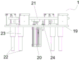
Fig. 1 is a schematic perspective view of the present invention;
FIG. 2 is a schematic perspective view of a product clamping module;
FIG. 3 is a schematic perspective view of a jacking module;
fig. 4 is a schematic plan view of the present invention;
fig. 5 is a schematic plan view of another viewing angle of the present invention.
Detailed Description
As shown in fig. 1 to 5, in this embodiment, the utility model discloses a jacking module 1, be provided with product centre gripping module 2 on the jacking module 1, be provided with product centre gripping station 3 on the product centre gripping module 2 and with the rotatory module 4 of 3 matched with products of product centre gripping station. Compared with the prior art not enough the utility model discloses in, jacking module 1 dispose in right product centre gripping module 2 carries out the jacking, product centre gripping module 2 dispose in carry out the centre gripping to the product, product rotation module 4 dispose in right product on the product centre gripping station 3 rotates, makes the utility model has the advantages of practice thrift cost and convenient to use.
In this embodiment, the product clamping module 2 comprises a bottom plate 5, a linear guide rail 6, a synchronous belt assembly 7 and a clamping cylinder 8 are arranged on the bottom plate 5, a first clamping component 9 and a second clamping component 10 are slidably matched on the linear guide rail 6, product jackets 11 are respectively arranged at the inner sides of the first clamping component 9 and the second clamping component 10, the product clamping station 3 is arranged between the two product jackets 11, the product rotating module 4 drives the two product jackets 11 to rotate, the movable end of the clamping cylinder 8 is matched with the first clamping assembly 9, one side of the synchronous belt assembly 7 is matched with the first clamping assembly 9, the other side transmission cooperation of hold-in range subassembly 7 has hold-in range centre gripping subassembly 12, hold-in range centre gripping subassembly 12 with second centre gripping subassembly 10 cooperatees. When the product clamping device is used, a product is placed on the product clamping station 3, the product is clamped by the two product clamping sleeves 11 at the moment, and when the product needs to be clamped, the movable end of the clamping cylinder 8 drives the first clamping assembly 9 to move towards the second clamping assembly 10, and simultaneously drives one side of the synchronous belt assembly 7 to move towards the second clamping assembly 10, so that the other side of the synchronous belt assembly 7 and the synchronous belt clamping assembly 12 are driven to move towards the first clamping assembly 9, the first clamping assembly 9 and the second clamping assembly 10 can clamp the product on the product clamping station 3, and the product rotating module 4 is configured to rotate the product on the product clamping station 3.
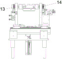
In this embodiment, the product rotation module 4 includes a first rotation module 13 and a second rotation module 14, the first rotation module 13 and the second rotation module 14 are respectively disposed on the outer side of the first clamping assembly 9 and the outer side of the second clamping assembly 10, the first rotation module 13 includes a rotating shaft 15, a rack 16 and a driving cylinder 17, the rotating shaft 15 is embedded in the first clamping assembly 9 and is matched with the product jacket 11, a gear 18 is sleeved on the rotating shaft 15, the rack 16 is engaged with the gear 18, and the driving cylinder 17 drives the rack 16 to make a linear motion. When the product needs to rotate, the driving cylinder 17 drives the rack 16 to do linear motion, so that the gear 18 and the rotating shaft 15 further rotate, and the product rotates.
In this embodiment, jacking module 1 includes jacking supporting seat 19, be provided with lift cylinder 20 on the jacking supporting seat 19, the cooperation is provided with jacking base 21 on the lift cylinder 20, jacking supporting seat 19 reaches be provided with a plurality of guiding axle 22 on the jacking base 21, product centre gripping module 2 sets up on the jacking base 21. When needing the jacking, through lift cylinder 20 drives jacking base 21 and a plurality of guiding axle 22 carries out the jacking, makes jacking base 21 can the jacking product centre gripping module 2.
In this embodiment, the guide shaft 22 is provided with a linear bearing 23, and the linear bearing 23 is arranged on the lower end surface of the jacking support seat 19.
In this embodiment, a first limit screw 24 is disposed between the jacking support seat 19 and the jacking base 21. First stop screw 24 can adjust the jacking height of jacking module 1.
In this embodiment, the clamping cylinder 8 is connected with a second limiting screw 25, and the second limiting screw 25 is matched with the inner side of the second clamping assembly 10. The second limit screw 25 can adjust the clamping stroke of the product.
While the embodiments of the present invention have been described in terms of practical embodiments, they are not intended to limit the scope of the invention, and modifications of the embodiments and combinations with other embodiments will be apparent to those skilled in the art in light of the present description.
Claims (7)
1. The utility model provides a centre gripping jacking rotary mechanism which characterized in that: the device comprises a jacking module (1), wherein a product clamping module (2) is arranged on the jacking module (1), a product clamping station (3) and a product rotating module (4) matched with the product clamping station (3) are arranged on the product clamping module (2).
2. The clamp jacking rotary mechanism of claim 1, wherein: the product clamping module (2) comprises a bottom plate (5), a linear guide rail (6), a synchronous belt assembly (7) and a clamping cylinder (8) are arranged on the bottom plate (5), a first clamping assembly (9) and a second clamping assembly (10) are arranged on the linear guide rail (6) in a sliding fit mode, product jackets (11) are arranged on the inner sides of the first clamping assembly (9) and the second clamping assembly (10), a product clamping station (3) is arranged between the two product jackets (11), the product rotating module (4) drives the two product jackets (11) to rotate, the movable end of the clamping cylinder (8) is matched with the first clamping assembly (9), one side of the synchronous belt assembly (7) is matched with the first clamping assembly (9), and the other side of the synchronous belt assembly (7) is matched with the synchronous belt clamping assembly (12) in a transmission mode, the synchronous belt clamping assembly (12) is matched with the second clamping assembly (10).
3. The clamp jacking rotary mechanism of claim 2, wherein: the product rotating module (4) comprises a first rotating module (13) and a second rotating module (14), the first rotating module (13) and the second rotating module (14) are respectively arranged on the outer side of the first clamping assembly (9) and the outer side of the second clamping assembly (10), the first rotating module (13) comprises a rotating shaft (15), a rack (16) and a driving cylinder (17), the rotating shaft (15) is embedded in the first clamping assembly (9) and matched with the product jacket (11), a gear (18) is sleeved on the rotating shaft (15), the rack (16) is meshed with the gear (18), and the driving cylinder (17) drives the rack (16) to do linear motion.
4. The clamp jacking rotary mechanism of claim 1, wherein: jacking module (1) is including jacking supporting seat (19), be provided with lift cylinder (20) on jacking supporting seat (19), the cooperation is provided with jacking base (21) on lift cylinder (20), jacking supporting seat (19) reach be provided with a plurality of guiding axle (22) on jacking base (21), product centre gripping module (2) sets up on jacking base (21).
5. The clamp jacking rotary mechanism of claim 4, wherein: the guide shaft (22) is provided with a linear bearing (23), and the linear bearing (23) is arranged on the lower end face of the jacking support seat (19).
6. The clamp jacking rotary mechanism of claim 4, wherein: a first limiting screw (24) is arranged between the jacking supporting seat (19) and the jacking base (21).
7. The clamp jacking rotary mechanism of claim 2, wherein: and a second limiting screw (25) is connected to the clamping cylinder (8), and the second limiting screw (25) is matched with the inner side of the second clamping assembly (10).
Priority Applications (1)
| Application Number | Priority Date | Filing Date | Title |
|---|---|---|---|
| CN202021459739.6U CN212858422U (en) | 2020-07-22 | 2020-07-22 | Clamping, jacking and rotating mechanism |
Applications Claiming Priority (1)
| Application Number | Priority Date | Filing Date | Title |
|---|---|---|---|
| CN202021459739.6U CN212858422U (en) | 2020-07-22 | 2020-07-22 | Clamping, jacking and rotating mechanism |
Publications (1)
| Publication Number | Publication Date |
|---|---|
| CN212858422U true CN212858422U (en) | 2021-04-02 |
Family
ID=75216478
Family Applications (1)
| Application Number | Title | Priority Date | Filing Date |
|---|---|---|---|
| CN202021459739.6U Active CN212858422U (en) | 2020-07-22 | 2020-07-22 | Clamping, jacking and rotating mechanism |
Country Status (1)
| Country | Link |
|---|---|
| CN (1) | CN212858422U (en) |
Cited By (1)
| Publication number | Priority date | Publication date | Assignee | Title |
|---|---|---|---|---|
| CN114473438A (en) * | 2022-03-03 | 2022-05-13 | 苏州天准科技股份有限公司 | Mounting device for components in a heat exchanger of a motor vehicle |
-
2020
- 2020-07-22 CN CN202021459739.6U patent/CN212858422U/en active Active
Cited By (1)
| Publication number | Priority date | Publication date | Assignee | Title |
|---|---|---|---|---|
| CN114473438A (en) * | 2022-03-03 | 2022-05-13 | 苏州天准科技股份有限公司 | Mounting device for components in a heat exchanger of a motor vehicle |
Similar Documents
| Publication | Publication Date | Title |
|---|---|---|
| CN102371499A (en) | Clamping device for manipulator | |
| CN211589118U (en) | Seamless connection device for butt joint of steel pipes | |
| CN212858422U (en) | Clamping, jacking and rotating mechanism | |
| CN209407186U (en) | A kind of traction device of open type press with fixed bench | |
| CN115945566B (en) | Target reporting workpiece processing and stamping device and method | |
| CN113442392A (en) | Commutator pressure injection molding equipment | |
| CN210501545U (en) | Transmission device of servo punch press | |
| CN216326185U (en) | Welding tool clamp for lifting tray | |
| CN210547286U (en) | Four-point toggle type high-speed punch press | |
| CN213504822U (en) | Diode handling device | |
| CN211247895U (en) | Pneumatic stamping equipment | |
| CN211161396U (en) | Double-station stamping device for circular plate | |
| CN212070199U (en) | Bending machine is with centre gripping structure of being convenient for change mould | |
| CN202862624U (en) | Multi-station turntable | |
| CN218098226U (en) | Vibrating device for production and detection of battery box | |
| CN215879984U (en) | Feeding device for rapid punching of bearing seat | |
| CN205511041U (en) | Tomato lateral bud excision device | |
| CN220502168U (en) | Clamping jaw convenient for loading rollers of various specifications | |
| CN213504823U (en) | Diode carrying manipulator | |
| CN217417361U (en) | Rotary blanking mechanism | |
| CN213136788U (en) | Part grabbing mechanism of precision machine | |
| CN211073045U (en) | Semi-automatic air conditioner panel wire drawing machine | |
| CN216462897U (en) | Hydraulic processing mechanism for preparing oil cylinder cover | |
| CN219925851U (en) | Jig for machining middle die movable base | |
| CN218398117U (en) | Automatic change manipulator |
Legal Events
| Date | Code | Title | Description |
|---|---|---|---|
| GR01 | Patent grant | ||
| GR01 | Patent grant |