CN218909374U - Wire rewinding machine or wire paying-off machine - Google Patents
Wire rewinding machine or wire paying-off machine Download PDFInfo
- Publication number
- CN218909374U CN218909374U CN202320205182.0U CN202320205182U CN218909374U CN 218909374 U CN218909374 U CN 218909374U CN 202320205182 U CN202320205182 U CN 202320205182U CN 218909374 U CN218909374 U CN 218909374U
- Authority
- CN
- China
- Prior art keywords
- motor
- machine
- fixed mounting
- wire
- rod
- Prior art date
- Legal status (The legal status is an assumption and is not a legal conclusion. Google has not performed a legal analysis and makes no representation as to the accuracy of the status listed.)
- Active
Links
Images

Abstract
The utility model discloses a wire winding machine or a wire paying-off machine, and particularly relates to the technical field of electric wire and cable auxiliary equipment. According to the utility model, the clamping seat can be driven to convey the cable through the first motor, the rotating roller can be used for winding the cable, the second motor can be used for driving the screw rod to rotate, the position of the guide wheel can be adjusted, the guide wheel can guide the cable, and the third motor can be used for driving the rotating screw rod to rotate, so that the rotating screw rod can separate and twist the cable.
Description
Technical Field
The utility model relates to the technical field of electric wire and cable auxiliary equipment, in particular to a wire winding machine or a wire paying-off machine.
Background
The paying-off machine is wire and cable auxiliary equipment which is matched with the wire twisting machine and plays a role in paying off. The paying-off machine can be generally divided into an active back-twist paying-off machine, a vertical power paying-off machine, a double-shaft multi-head wire drawing disc active paying-off machine, a shaftless paying-off machine and the like. The stranding machine is a stranding mechanical device which can be widely applied to various soft/hard conductor wires, so that a plurality of single conductors are twisted into one strand, and the technical requirement of the wires is met. The stranding machine can be generally divided into a single stranding machine, a pair stranding machine, a high-speed stranding machine, a back-twisting machine, a cage stranding machine, a frame work stranding machine, a tubular stranding machine, a disc stranding machine and the like according to a stranding mode.
The prior art has the following defects: when the existing wire winding machine or paying-off machine winds and winds the cable, the cable can be processed by using an independent wire winding machine or paying-off machine, two functions cannot be integrated together, further the cable cannot be processed rapidly, and the processing efficiency of the cable can be affected.
Disclosure of Invention
Therefore, the embodiment of the utility model provides a wire rewinding machine or a wire paying-off machine, which solves the problem of low processing efficiency of a cable wire caused by the fact that stranded wires and separation functions cannot be combined together in the prior art.
In order to achieve the above object, the embodiment of the present utility model provides the following technical solutions: the utility model provides a wire winding machine or paying out machine, includes the support base, the top fixed mounting of support base has the mount, one side fixed mounting of mount has the control box, one side bottom of mount is provided with first motor, the output outside of first motor is provided with the action wheel, one side rotation of mount top one end is installed the axis of rotation, one end outside fixed mounting of axis of rotation has from the driving wheel, be provided with the drive belt and pass through drive belt swing joint between from driving wheel and the action wheel, the other end fixed mounting of axis of rotation has the joint seat, the opposite side fixed mounting of mount top one end has fixed sleeve, fixed sleeve's inner wall rotation installation adjusting screw, adjusting screw's one end fixed mounting has adjust knob, the outside screw thread of adjusting screw has cup jointed the movable rod, the one end fixed mounting of movable rod has the top cone, the one end outside fixed mounting that the axis of rotation is close to the joint seat has driving sprocket, the inboard rotation of mount is installed the installation pole, one end outside fixed mounting of installation pole has driven sprocket, be provided with transmission and pass through drive belt swing joint between driven sprocket and the action wheel, the other end of installation link has the top strand wires to rotate the mechanism, the top is provided with the wire guide mechanism.
Preferably, the guide mechanism comprises a screw rod, two ends of the screw rod are respectively and rotatably connected with two ends of the top of the fixing frame, and the outer side thread of the screw rod is sleeved with a guide wheel.
Preferably, a second motor is fixedly arranged on one side of the top of the fixing frame, and the second motor is in transmission connection with the screw rod through an output shaft.
Preferably, the stranding mechanism comprises a rotating screw rod, and the rotating screw rod is rotationally connected with one end of the top of the fixing frame.
Preferably, a third motor is fixedly arranged at one end of the fixing frame and is fixedly connected with the rotating screw rod, and the third motor is in transmission connection with the rotating screw rod through an output shaft.
Preferably, the top of the movable rod is provided with a limiting groove, and the outer wall of the movable rod is movably connected with the inner wall of the fixed sleeve.
Preferably, the top of the fixed sleeve is rotatably provided with a limiting rod, and the bottom of the limiting rod penetrates through the outer wall of the top of the fixed sleeve and is movably connected with the inner wall of the limiting groove.
Preferably, one side of one end of the bottom of the fixing frame is fixedly connected with a first motor, and the first motor is in transmission connection with the driving wheel through an output shaft.
The embodiment of the utility model has the following advantages:
1. according to the utility model, through the arrangement of the rotating roller and the rotating screw, the first motor works to enable the rotating shaft to rotate through the transmission action of the driving wheel, the driven wheel and the transmission belt, so that the clamping seat can be driven to convey the cable, meanwhile, the rotating roller rotates through the transmission action of the driving chain wheel, the driven chain wheel and the transmission chain, so that the cable can be wound, the second motor works to drive the screw rod to rotate, so that the position of the guide wheel can be adjusted, the guide wheel can guide the cable, and meanwhile, the third motor works to drive the rotating screw to rotate, so that the rotating screw can separate and twist the cable, and winding, twisting and separating of the cable are more convenient;
2. according to the utility model, through the arrangement of the limiting rod and the limiting groove, the movement of the movable rod can be limited by the connection between the limiting rod and the limiting groove, so that the movable rod is stable in the adjusting process, the tip cone can be stably connected with the clamping seat, and further, the cable is more convenient to convey.
Drawings
In order to more clearly illustrate the embodiments of the present utility model or the technical solutions in the prior art, the drawings used in the description of the embodiments or the prior art will be briefly described below. It will be apparent to those of ordinary skill in the art that the drawings in the following description are exemplary only and that other implementations can be obtained from the extensions of the drawings provided without inventive effort.
The structures, proportions, sizes, etc. shown in the present specification are shown only for the purposes of illustration and description, and are not intended to limit the scope of the utility model, which is defined by the claims, so that any structural modifications, changes in proportions, or adjustments of sizes, which do not affect the efficacy or the achievement of the present utility model, should fall within the ambit of the technical disclosure.
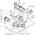
FIG. 1 is a schematic diagram of the overall structure of the present utility model;
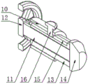
FIG. 2 is a perspective view of a fixing mechanism according to the present utility model;
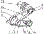
FIG. 3 is a perspective view of a winding mechanism of the present utility model;
fig. 4 is a perspective view of the adjusting mechanism of the present utility model.
In the figure: 1. a support base; 2. a fixing frame; 3. a control box; 4. a first motor; 5. a driving wheel; 6. a rotating shaft; 7. driven wheel; 8. a transmission belt; 9. a clamping seat; 10. fixing the sleeve; 11. adjusting a screw; 12. an adjustment knob; 13. a movable rod; 14. a tip cone; 15. defining a slot; 16. a limiting rod; 17. a drive sprocket; 18. a mounting rod; 19. a driven sprocket; 20. a drive chain; 21. a rotating roller; 22. a screw rod; 23. a guide wheel; 24. a second motor; 25. a third motor; 26. the screw is turned.
Detailed Description
Other advantages and advantages of the present utility model will become apparent to those skilled in the art from the following detailed description, which, by way of illustration, is to be read in connection with certain specific embodiments, but not all embodiments. All other embodiments, which can be made by those skilled in the art based on the embodiments of the utility model without making any inventive effort, are intended to be within the scope of the utility model.
Referring to the accompanying drawings 1-4 of the specification, the wire winding machine or wire unwinding machine of the embodiment comprises a supporting base 1, wherein a fixing frame 2 is fixedly arranged at the top of the supporting base 1, a control box 3 is fixedly arranged at one side of the fixing frame 2, a first motor 4 is arranged at the bottom of one side of the fixing frame 2, a driving wheel 5 is arranged at the outer side of an output end of the first motor 4, a rotating shaft 6 is rotatably arranged at one side of one end of the top of the fixing frame 2, a driven wheel 7 is fixedly arranged at the outer side of one end of the rotating shaft 6, a driving belt 8 is arranged between the driven wheel 7 and the driving wheel 5 and is movably connected with the driving wheel 5 through the driving belt 8, a clamping seat 9 is fixedly arranged at the other end of the rotating shaft 6, a fixed sleeve 10 is fixedly arranged at the other side of one end of the top of the fixing frame 2, an adjusting screw 11 is rotatably arranged on the inner wall of the fixed sleeve 10, an adjusting knob 12 is fixedly arranged at one end of the adjusting screw 11, the outside screw thread of adjusting screw 11 has cup jointed movable rod 13, the one end fixed mounting of movable rod 13 has tip cone 14, the one end outside that axis of rotation 6 is close to joint seat 9 fixed mounting has driving sprocket 17, the inboard rotation of mount 2 has installed installation pole 18, the one end outside fixed mounting of installation pole 18 has driven sprocket 19, be provided with drive chain 20 and pass through drive chain 20 swing joint between driven sprocket 19 and the driving sprocket 17, the other end outside fixed mounting of installation pole 18 has rotor 21, the top of mount 2 is provided with guiding mechanism, the top other end of mount 2 is provided with stranded conductor mechanism, adjust knob 12 work makes tip cone 14 can be connected with joint seat 9, and first motor 4 work makes joint seat 9 and rotor 21 take place to rotate, and then can wind the cable conductor, can carry out stranded conductor and unwrapping wire to the cable conductor through guiding mechanism and stranded conductor mechanism.
Further, in the above technical scheme, guiding mechanism includes lead screw 22, lead screw 22 both ends respectively with mount 2 top both ends rotate to be connected, the outside screw thread of lead screw 22 has cup jointed leading wheel 23, and mount 2 can install and fix lead screw 22, and lead screw 22 rotates the position that can adjust leading wheel 23, can lead the cable conductor through leading wheel 23, the top one side fixed mounting of mount 2 has second motor 24, pass through output shaft transmission connection between second motor 24 and the lead screw 22, and mount 2 can install and fix second motor 24, and second motor 24 work can drive lead screw 22 and take place to rotate, and then can provide power for the removal of leading wheel 23.
Further, in the above technical scheme, stranded conductor mechanism includes rotation screw rod 26, rotation screw rod 26 rotates with the top one end of mount 2 to be connected, and mount 2 can install and fix rotation screw rod 26, and rotation screw rod 26 can separate and strand the cable conductor, the one end fixed mounting of mount 2 has third motor 25 fixed connection, be connected through output shaft transmission between third motor 25 and the rotation screw rod 26, and mount 2 can install and fix third motor 25, and third motor 26 work can drive rotation screw rod 26 and rotate, and then can strand and separate the cable conductor.
Further, in the above technical solution, the top of the movable rod 13 is provided with the limiting groove 15, the outer wall of the movable rod 13 is movably connected with the inner wall of the fixed sleeve 10, the movable rod 13 can move on the inner wall of the fixed sleeve 10, the top of the fixed sleeve 10 is rotatably provided with the limiting rod 16, the bottom of the limiting rod 16 penetrates through the outer wall of the top of the fixed sleeve 10 and is movably connected with the inner wall of the limiting groove 15, the fixed sleeve 10 can install and fix the limiting rod 16, and the connection between the limiting rod 16 and the limiting groove 15 can limit the movement of the movable rod 13.
Further, in the above technical scheme, one side of mount 2 bottom one end and first motor 4 fixed connection, be connected through output shaft transmission between first motor 4 and the action wheel 5, mount 2 can install and fix first motor 4, and first motor 4 work can drive action wheel 5 and take place to rotate, and then can provide power for the rotation of cassette 9 and live-rollers 21.
The implementation scene is specifically as follows: when receive and release the cable, make adjusting screw 11 rotate through rotating adjust knob 12, and then can drive movable rod 13 along the inner wall of fixed sleeve 10 towards joint seat 9 removal, can fix the cable through being connected between tip cone 14 and the joint seat 9, first motor 4 work can drive action wheel 5 and rotate, the transmission effect through drive belt 8, make from driving wheel 7 rotate, and then can drive axis of rotation 6 and rotate, and then can drive joint seat 9 and rotate, and then can carry the cable, axis of rotation 6 rotates and can drive sprocket 17 and rotate, the transmission effect through drive chain 20, make driven sprocket 19 rotate, and then can drive installation pole 18 and rotate, and then can drive the rotor roller 21 and wind the cable, when twining the cable, second motor 24 work can drive lead screw 22 and rotate, and then can drive leading wheel 23 and remove in the lead screw 22 outside, and then can adjust leading wheel 23's position, make it twine the rotation motor 25 outside through leading wheel 23, and then can carry out the rotation of drive sprocket 17, and then can rotate through leading wheel 23, and then make the cable 25 rotate with the third cable 26, and then can rotate, and then can be twisted with the realization of the cable, and then can be more convenient and more specific cable can be released and can be realized, and the cable can not be twisted to the realization of the current technology of the realization of the cable is more convenient.
While the utility model has been described in detail in the foregoing general description and specific examples, it will be apparent to those skilled in the art that modifications and improvements can be made thereto. Accordingly, such modifications or improvements may be made without departing from the spirit of the utility model and are intended to be within the scope of the utility model as claimed.
Claims (8)
1. The utility model provides a admission machine or paying out machine, includes support base (1), its characterized in that: the utility model discloses a sprocket wheel, including support base (1), fixed mounting has mount (2) in the top of support base (1), one side fixed mounting of mount (2) has control box (3), one side bottom of mount (2) is provided with first motor (4), the output outside of first motor (4) is provided with action wheel (5), one side rotation of mount (2) top one end is installed axis of rotation (6), the one end outside fixed mounting of axis of rotation (6) has from driving wheel (7), be provided with drive belt (8) and pass through drive belt (8) swing joint between driving wheel (7) and action wheel (5), the other side fixed mounting of axis of rotation (6) has joint seat (9), the opposite side fixed mounting of mount (2) top one end has fixed sleeve (10), the inner wall rotation of fixed sleeve (10) is installed adjusting screw (11), the one end fixed mounting of adjusting screw (12), the outside screw thread of adjusting screw (11) has cup jointed movable rod (13), the one end fixed mounting of movable rod (13) has a tip cone (14), the other end fixed mounting of axis of rotation (6) is close to sprocket wheel (9) installs inside fixed mounting seat (17), the novel wire twisting device is characterized in that a driven sprocket (19) is fixedly arranged outside one end of the mounting rod (18), a transmission chain (20) is arranged between the driven sprocket (19) and the driving sprocket (17) and is movably connected through the transmission chain (20), a rotating roller (21) is fixedly arranged outside the other end of the mounting rod (18), a guide mechanism is arranged at the top of the fixing frame (2), and a wire twisting mechanism is arranged at the other end of the top of the fixing frame (2).
2. A wire takeup or payoff machine as claimed in claim 1, wherein: the guide mechanism comprises a screw rod (22), two ends of the screw rod (22) are respectively and rotatably connected with two ends of the top of the fixing frame (2), and a guide wheel (23) is sleeved on the outer side thread of the screw rod (22).
3. A wire takeup or payoff machine as claimed in claim 2, wherein: a second motor (24) is fixedly arranged on one side of the top of the fixing frame (2), and the second motor (24) is connected with the screw rod (22) through an output shaft in a transmission way.
4. A wire takeup or payoff machine as claimed in claim 1, wherein: the wire twisting mechanism comprises a rotating screw rod (26), and the rotating screw rod (26) is rotationally connected with one end of the top of the fixing frame (2).
5. A wire takeup or payoff machine as claimed in claim 4, wherein: one end of the fixing frame (2) is fixedly provided with a third motor (25) which is fixedly connected, and the third motor (25) is connected with the rotating screw (26) through an output shaft in a transmission way.
6. A wire takeup or payoff machine as claimed in claim 1, wherein: the top of the movable rod (13) is provided with a limiting groove (15), and the outer wall of the movable rod (13) is movably connected with the inner wall of the fixed sleeve (10).
7. A wire takeup or payoff machine as claimed in claim 6, wherein: the top of the fixed sleeve (10) is rotatably provided with a limiting rod (16), and the bottom of the limiting rod (16) penetrates through the outer wall of the top of the fixed sleeve (10) and is movably connected with the inner wall of the limiting groove (15).
8. A wire takeup or payoff machine as claimed in claim 1, wherein: one side of one end of the bottom of the fixing frame (2) is fixedly connected with the first motor (4), and the first motor (4) is connected with the driving wheel (5) through an output shaft in a transmission way.
Priority Applications (1)
| Application Number | Priority Date | Filing Date | Title |
|---|---|---|---|
| CN202320205182.0U CN218909374U (en) | 2023-02-14 | 2023-02-14 | Wire rewinding machine or wire paying-off machine |
Applications Claiming Priority (1)
| Application Number | Priority Date | Filing Date | Title |
|---|---|---|---|
| CN202320205182.0U CN218909374U (en) | 2023-02-14 | 2023-02-14 | Wire rewinding machine or wire paying-off machine |
Publications (1)
| Publication Number | Publication Date |
|---|---|
| CN218909374U true CN218909374U (en) | 2023-04-25 |
Family
ID=86040443
Family Applications (1)
| Application Number | Title | Priority Date | Filing Date |
|---|---|---|---|
| CN202320205182.0U Active CN218909374U (en) | 2023-02-14 | 2023-02-14 | Wire rewinding machine or wire paying-off machine |
Country Status (1)
| Country | Link |
|---|---|
| CN (1) | CN218909374U (en) |
Cited By (1)
| Publication number | Priority date | Publication date | Assignee | Title |
|---|---|---|---|---|
| CN116213594A (en) * | 2023-05-06 | 2023-06-06 | 大名县正光电缆有限公司 | Copper wire stranding machine with copper wire winding and unwinding functions |
-
2023
- 2023-02-14 CN CN202320205182.0U patent/CN218909374U/en active Active
Cited By (1)
| Publication number | Priority date | Publication date | Assignee | Title |
|---|---|---|---|---|
| CN116213594A (en) * | 2023-05-06 | 2023-06-06 | 大名县正光电缆有限公司 | Copper wire stranding machine with copper wire winding and unwinding functions |
Similar Documents
| Publication | Publication Date | Title |
|---|---|---|
| CN218909374U (en) | Wire rewinding machine or wire paying-off machine | |
| CN216311447U (en) | Cable production stranded conductor device | |
| CN209747243U (en) | Wire twisting device | |
| CN208673811U (en) | Integral type pipe twisting machine | |
| CN212967248U (en) | Automatic wire stranding device for copper-clad aluminum enameled wire | |
| CN109065274B (en) | Torsion-free cabling machine | |
| CN216512101U (en) | Unwinding device for cable manufacturing | |
| CN116313294A (en) | Cable stranding machine | |
| CN215496181U (en) | Cage type wire twisting machine | |
| CN212799054U (en) | Coiling mechanism of line machine is stretched to copper line | |
| CN209815381U (en) | Two-in-one conductor rewinder with wire storage protection function | |
| CN110706866B (en) | Cable pair twister | |
| CN209591665U (en) | A kind of four times of stranding machines | |
| CN114345982A (en) | Aluminum wire processing wire drawing machine | |
| CN217229725U (en) | Pay-off rack for cable production | |
| CN220189322U (en) | Wire twisting machine for cable preparation | |
| CN210896776U (en) | Winding structure for cable production | |
| CN212831999U (en) | Automatic tightness adjusting mechanism for cable paying-off | |
| CN100561618C (en) | The method of high speed winding tinsel and device thereof on heart yearn | |
| CN210150461U (en) | Back-twist barrel type pay-off device | |
| CN219143875U (en) | Frame winch traction device for cable production | |
| CN212907236U (en) | Double-stranding machine for cable production | |
| CN219575249U (en) | Frame type stranding machine for cable processing | |
| CN219575248U (en) | Paying-off device of pipe strander for cable processing | |
| CN214569742U (en) | Cable processing wind |
Legal Events
| Date | Code | Title | Description |
|---|---|---|---|
| GR01 | Patent grant | ||
| GR01 | Patent grant |