CN218876273U - Compound laminating machine of multilayer material - Google Patents
Compound laminating machine of multilayer material Download PDFInfo
- Publication number
- CN218876273U CN218876273U CN202223159911.8U CN202223159911U CN218876273U CN 218876273 U CN218876273 U CN 218876273U CN 202223159911 U CN202223159911 U CN 202223159911U CN 218876273 U CN218876273 U CN 218876273U
- Authority
- CN
- China
- Prior art keywords
- film
- roller
- base
- bracket
- workbench
- Prior art date
- Legal status (The legal status is an assumption and is not a legal conclusion. Google has not performed a legal analysis and makes no representation as to the accuracy of the status listed.)
- Active
Links
Images


Abstract
The utility model discloses a compound laminating machine of multilayer material, include: the inner side of the base is provided with a workbench, and at least part of the workbench is positioned outside the base; the film covering mechanism is arranged on the inner side of the base, and at least part of the film covering mechanism and the workbench are positioned on the same plane; the brackets are symmetrically arranged at the top of the base; the mounting assembly is arranged on the bracket on one side; the adjusting assembly is arranged on the bracket on the other side, and the adjusting assembly and the mounting assembly are positioned on the same plane; a film roll disposed between the mounting assembly and the adjustment assembly. The utility model discloses can cover different films on the material surface simultaneously, can also adjust the tectorial membrane order of different films through adjusting part, improve the efficiency of material tectorial membrane greatly, reduce the cost of tectorial membrane, quality when can guarantee the material tectorial membrane simultaneously reduces the waste of film, more practicality.
Description
Technical Field
The utility model relates to a laminating machine, especially a compound laminating machine of multilayer material.
Background
The laminating machine can be used for laminating films with different functions on the surface of a material in a hot pressing mode to form a unified material, so that the material can play a corresponding role. Has the characteristics of compact structure, small volume, low cost, simple and convenient operation and good product quality stability.
The existing film laminating machine can not simultaneously coat different films on the surface of the material, so that the film laminating efficiency is low and the film laminating cost is high; and when covering multilayer film, there is the deviation between the multilayer film, and the tectorial membrane quality is difficult to guarantee, causes the waste of film easily, and the practicality is relatively poor.
SUMMERY OF THE UTILITY MODEL
The utility model aims at providing a compound laminating machine of multilayer material to solve the technical problem among the prior art, it can cover different films on the material surface simultaneously, has improved the efficiency of material tectorial membrane greatly, has reduced the cost of tectorial membrane, and the quality when can guarantee the material tectorial membrane simultaneously reduces the waste of film, more practicality.
The utility model provides a compound laminating machine of multilayer material, include: the device comprises a base, wherein a workbench is arranged on the inner side of the base, and at least part of the workbench is positioned outside the base; the film covering mechanism is arranged on the inner side of the base, and at least part of the film covering mechanism and the workbench are positioned on the same plane; the brackets are symmetrically arranged at the top of the base; the mounting assembly is arranged on the bracket on one side; the adjusting assembly is arranged on the bracket on the other side, and the adjusting assembly and the mounting assembly are positioned on the same plane; a film roll disposed between the mounting assembly and the adjustment assembly.
According to the technical scheme of the embodiment of the application, when the material is coated, the film rollers with different films can be respectively installed between the installation assembly and the adjusting assembly, the different films are sequentially coated on the surface of the material through the film coating mechanism, and meanwhile, the film coating sequence of the different films can be adjusted through the adjusting assembly, so that the different films are coated on the surface of the material, the film coating efficiency of the material is greatly improved, and the film coating cost is reduced; furthermore, the condition that deviation occurs among the multiple layers of thin films when the materials are coated with the films step by step can be avoided, the quality of the materials during film coating is guaranteed, waste of the thin films during film coating is reduced, and the practicability of the device is improved.
Preferably, the laminating mechanism comprises two first press rollers, a second press roller, a third press roller and a fourth press roller which are all arranged on the inner side of the base, and the top of the workbench is positioned between the two first press rollers, the two second press rollers, the two third press rollers and the four fourth press rollers. Can be through first compression roller, second compression roller and third compression roller like this to the different film coating on the surface of material, guarantee the tectorial membrane quality of material through the fourth compression roller at last.
Preferably, the laminating mechanism further comprises a first tensioning wheel, a second tensioning wheel and a third tensioning wheel which are all arranged on the inner side of the base, wherein the first tensioning wheel is positioned above the space between the first pressing roller and the second pressing roller, the second tensioning wheel is positioned above the space between the second pressing roller and the third pressing roller, and the third tensioning wheel is positioned above the space between the third pressing roller and the fourth pressing roller. Therefore, when different films are coated on the material, the tension force of the material is ensured, and the material is prevented from being folded when being coated with the film.
Preferably, the mounting assembly comprises: the movable shaft is arranged on the bracket, and at least part of two ends of the movable shaft is positioned outside the bracket; the limiting strip is arranged outside the movable shaft; one end of the spring is connected with the bracket, the other end of the spring is connected with the end part of the movable shaft, and the movable shaft is positioned in the spring; and the first fixing plate is rotatably connected to one end, far away from the spring, of the movable shaft. The movable shaft can be pulled outwards to realize quick assembly and disassembly of the film roller, so that different films can be conveniently coated with materials.
Preferably, the adjusting assembly includes a rotating shaft and a second fixing plate, the rotating shaft is disposed on the other of the brackets, at least a portion of two ends of the rotating shaft is located outside the brackets, and the second fixing plate is disposed at one end of the rotating shaft close to the first fixing plate. The positions of different film rollers can be adjusted by rotating the rotating shaft, so that the film covering sequence of different films and the film covering of materials are facilitated.
Preferably, one side of the first fixing plate, which is close to the second fixing plate, is correspondingly provided with three positioning columns, two ends of the film roller are provided with holes matched with the positioning columns, and the film roller is arranged between the first fixing plate and the second fixing plate through the positioning columns. The effect of quick installation dismantlement can be realized when can guaranteeing that different membrane rollers are stable like this.
Compared with the prior art, the utility model discloses can cover different films on the material surface simultaneously, can also adjust the tectorial membrane order of different films through adjusting part, improve the efficiency of material tectorial membrane greatly, reduce the cost of tectorial membrane, quality when can guarantee the material tectorial membrane simultaneously reduces the waste of film, more practicality.
Drawings
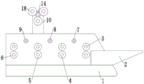
Fig. 1 is a schematic view of a first three-dimensional structure of the present invention;
fig. 2 is a schematic view of a second three-dimensional structure of the present invention;
fig. 3 is a schematic side view of the cross-sectional structure of the present invention;
FIG. 4 is a schematic structural view of the bracket, the fixing assembly, the adjusting assembly and the film roller of the present invention;
fig. 5 is a schematic structural diagram of the bracket and the fixing component of the present invention.
Description of reference numerals: 1. a base; 2. a work table; 3. a first press roll; 4. a second press roll; 5. a third press roll; 6. a fourth press roll; 7. a first tensioning wheel; 8. a second tensioning wheel; 9. a third tension pulley; 10. a support; 11. a movable shaft; 12. a limiting strip; 13. a spring; 14. a first fixing plate; 15. a positioning column; 16. a rotating shaft; 17. a second fixing plate; 18. and (4) a film roller.
Detailed Description
Embodiments of the present invention will be described in detail below with reference to the accompanying drawings. The following examples are merely used to more clearly illustrate the technical solutions of the present application, and therefore are only examples, and the protection scope of the present application is not limited thereby.
Unless defined otherwise, all technical and scientific terms used herein have the same meaning as commonly understood by one of ordinary skill in the art to which this application belongs; the terminology used herein is for the purpose of describing particular embodiments only and is not intended to be limiting of the application; the terms "including" and "having," and any variations thereof, in the description and claims of this application and the description of the above figures are intended to cover non-exclusive inclusions.
In the description of the embodiments of the present application, the technical terms "first", "second", and the like are used only for distinguishing different objects, and are not to be construed as indicating or implying relative importance or implicitly indicating the number, specific order, or primary-secondary relationship of the technical features indicated. In the description of the embodiments of the present application, "a plurality" means two or more unless specifically defined otherwise.
Reference herein to "an embodiment" means that a particular feature, structure, or characteristic described in connection with the embodiment can be included in at least one embodiment of the application. The appearances of the phrase in various places in the specification are not necessarily all referring to the same embodiment, nor are separate or alternative embodiments mutually exclusive of other embodiments. It is explicitly and implicitly understood by one skilled in the art that the embodiments described herein may be combined with other embodiments.
In the description of the embodiments of the present application, the term "and/or" is only one kind of association relationship describing an associated object, and means that three relationships may exist, for example, a and/or B, and may mean: a exists alone, A and B exist simultaneously, and B exists alone. In addition, the character "/" herein generally indicates that the former and latter related objects are in an "or" relationship.
In the description of the embodiments of the present application, the term "plurality" refers to two or more (including two), and similarly, "plural sets" refers to two or more (including two), and "plural pieces" refers to two or more (including two).
In the description of the embodiments of the present application, the terms "center", "longitudinal", "transverse", "length", "width", "thickness", "up", "down", "front", "back", "left", "right", "vertical", "horizontal", "top", "bottom", "inner", "outer", "clockwise", "counterclockwise", "axial", "radial", "circumferential", and the like, indicate orientations and positional relationships that are based on the orientations and positional relationships shown in the drawings, and are used for convenience in describing the embodiments of the present application and for simplification of the description, but do not indicate or imply that the device or element referred to must have a specific orientation, be configured and operated in a specific orientation, and thus, should not be construed as limiting the embodiments of the present application.
In the description of the embodiments of the present application, unless otherwise explicitly stated or limited, the terms "mounted," "connected," "fixed," and the like are used in a broad sense, and for example, may be fixedly connected, detachably connected, or integrated; mechanical connection or electrical connection is also possible; either directly or indirectly through intervening media, either internally or in any other relationship. The specific meanings of the above terms in the embodiments of the present application can be understood by those of ordinary skill in the art according to specific situations.
As shown in fig. 1-3, embodiments of the present invention provide a multi-layer composite laminator, comprising: the device comprises a base 1, wherein a workbench 2 is arranged on the inner side of the base 1, and at least part of the workbench 2 is positioned outside the base 1; the film coating mechanism is arranged on the inner side of the base 1, and at least part of the film coating mechanism and the workbench 2 are positioned on the same plane; the brackets 10 are symmetrically arranged at the top of the base 1; a mounting assembly provided on the bracket 10 at one side thereof; the adjusting component is arranged on the bracket 10 at the other side, and the adjusting component and the mounting component are positioned on the same plane; and a film roll 18 disposed between the mounting assembly and the adjustment assembly.
According to the technical scheme of the embodiment of the application, when the material is coated, the film rollers 18 with different films can be respectively installed between the installation assembly and the adjusting assembly, the different films are sequentially coated on the surface of the material through the film coating mechanism, and meanwhile, the film coating sequence of the different films can be adjusted through the adjusting assembly, so that the different films are coated on the surface of the material, the film coating efficiency of the material is greatly improved, and the film coating cost is reduced; furthermore, the condition that deviation occurs among the multiple layers of thin films when the materials are coated with the films step by step can be avoided, the quality of the materials during film coating is guaranteed, waste of the thin films during film coating is reduced, and the practicability of the device is improved.
In the embodiment provided by the present application, as shown in fig. 3, the laminating mechanism includes two first pressing rollers 3, a second pressing roller 4, a third pressing roller 5, and a fourth pressing roller 6, all disposed on the inner side of the base 1, and the top of the working table 2 is located between the two first pressing rollers 3, the second pressing roller 4, the third pressing roller 5, and the fourth pressing roller 6.
In the embodiment provided by the present application, as shown in fig. 3, the laminating mechanism further includes a first tension wheel 7, a second tension wheel 8 and a third tension wheel 9, which are all disposed on the inner side of the base 1, wherein the first tension wheel 7 is located above between the first pressing roller 3 and the second pressing roller 4, the second tension wheel 8 is located above between the second pressing roller 4 and the third pressing roller 5, and the third tension wheel 9 is located above between the third pressing roller 5 and the fourth pressing roller 6.
The first tensioning wheel 7, the second tensioning wheel 8 and the third tensioning wheel 9 can ensure the tensioning force of the material after different films are coated, and the phenomenon that the subsequent coating work of the material is influenced by the wrinkles and the like of the material after coating is avoided.
In the embodiments provided herein, as shown in fig. 2, 4 and 5, the mounting assembly includes: the movable shaft 11 is arranged on the bracket 10, and two ends of the movable shaft 11 are at least partially positioned outside the bracket 10; the limiting strip 12 is arranged outside the movable shaft 11; a spring 13, one end of which is connected with the bracket 10, the other end of which is connected with the end part of the movable shaft 11, and the movable shaft 11 is positioned inside the spring 13; and a first fixing plate 14 rotatably connected to an end of the movable shaft 11 away from the spring 13.
When the film roller 18 is installed, the movable shaft 11 is pulled outwards, the first fixing plate 14 can be driven to move, so that the film roller 18 is conveniently installed, the movable shaft 11 is loosened after the other side of the film roller 18 is installed, the film roller 18 can be automatically fixed, and the film roller 18 is quickly installed and detached.
In the embodiment provided by the present application, as shown in fig. 1 and 4, the adjusting assembly includes a rotating shaft 16 and a second fixing plate 17, the rotating shaft 16 is disposed on the other bracket 10, two ends of the rotating shaft 16 are at least partially located outside the bracket 10, and the second fixing plate 17 is disposed at one end of the rotating shaft 16 close to the first fixing plate 14.
The rotation mode between 16 and the support 10 of pivot adopts the gear rotation mode, and technical scheme among the prior art can be referred to specific structure, and technical personnel in this field can know, does not do this and describe repeatedly, through rotating pivot 16, can adjust the position of different membrane rollers 18 to the tectorial membrane order of different films is adjusted, the efficiency of material tectorial membrane has further been improved.
In the embodiment provided by the present application, as shown in fig. 1, fig. 2 and fig. 4, three positioning pillars 15 are correspondingly disposed on the sides of the first fixing plate 14 and the second fixing plate 17 close to each other, holes adapted to the positioning pillars 15 are disposed at two ends of the film roller 18, and the film roller 18 is disposed between the first fixing plate 14 and the second fixing plate 17 through the positioning pillars 15.
When installing membrane roller 18, aim at the reference column 15 of second fixed plate 17 one side with the pore pair in the membrane roller 18 outside to fix the one end of membrane roller 18, aim at the reference column 15 of first fixed plate 14 one side with the pore pair in membrane roller 18 opposite side again, can install membrane roller 18 between first fixed plate 14 and second fixed plate 17.
The utility model discloses a use method: when the materials are coated with different films, firstly, the materials are pushed to a first press roller 3 on a workbench 2, meanwhile, the film on a film roller 18 on one side of the first press roller 3 is arranged on the surface of the materials in a close manner, the film can be coated and pressed on the surface of the materials through the first press roller, then the materials are wound on a first tension wheel 7, when the materials pass through a second press roller 4, the film outside a bottom film roller 18 is arranged on the previous film, the other film can be coated and pressed on the previous film through the second press roller 4, the processes are repeated, the film on the other film roller 18 can be coated and pressed on the previous film through a third press roller 5, and finally, the quality of the material coating can be ensured through a fourth press roller 6; in the laminating process, the first tensioning wheel 7, the second tensioning wheel 8 and the third tensioning wheel 9 can ensure the tensioning force of the material, and the condition that the material is folded is avoided.
When installing membrane roller 18, outwards stimulate loose axle 11, with the reference column 15 of the pore pair second fixed plate 17 one side in the membrane roller 18 outside, with the reference column 15 of the pore pair first fixed plate 14 one side in the membrane roller 18 opposite side simultaneously, loosen loose axle 11, under the effect of spring 13, can drive first fixed plate 14 to the motion of second fixed plate 17 one side, thereby fix membrane roller 18 between first fixed plate 14 and second fixed plate 17, spacing 12 then can guarantee spring 13's result of use.
When the film laminating sequence of the film needs to be adjusted, the rotating shaft 16 is rotated to drive the second fixing plate 17 and the first fixing plate 14 to rotate, so that the positions of different film rollers 18 are adjusted, the film laminating sequence of different films is adjusted, the film laminating efficiency of the material is greatly improved, and the film laminating quality of the material is ensured.
The above description is only for the preferred embodiment of the present invention, but the present invention is not limited to the implementation scope shown in the drawings, and all changes made according to the conception of the present invention or equivalent embodiments modified to equivalent changes are not beyond the spirit covered by the description and drawings, and should be within the protection scope of the present invention.
Claims (6)
1. A multi-layer material composite laminating machine, characterized by comprising:
the inner side of the base is provided with a workbench, and at least part of the workbench is positioned outside the base;
the film covering mechanism is arranged on the inner side of the base, and at least part of the film covering mechanism and the workbench are positioned on the same plane;
the brackets are symmetrically arranged at the top of the base;
the mounting assembly is arranged on the bracket on one side;
the adjusting assembly is arranged on the bracket on the other side, and the adjusting assembly and the mounting assembly are positioned on the same plane;
a film roll disposed between the mounting assembly and the adjustment assembly.
2. A multi-layer composite laminator according to claim 1, wherein: the laminating mechanism comprises two first compression rollers, a second compression roller, a third compression roller and a fourth compression roller which are all arranged on the inner side of the base, and the top of the workbench is located between the first compression roller, the second compression roller, the third compression roller and the fourth compression roller.
3. A multi-layer composite film applicator as recited in claim 2, wherein: the laminating mechanism further comprises a first tensioning wheel, a second tensioning wheel and a third tensioning wheel which are arranged on the inner side of the base, wherein the first tensioning wheel is positioned above the first pressing roller and the second pressing roller, the second tensioning wheel is positioned above the second pressing roller and the third pressing roller, and the third tensioning wheel is positioned above the third pressing roller and the fourth pressing roller.
4. A multi-layer composite laminator according to claim 1, wherein: the mounting assembly includes:
the movable shaft is arranged on the bracket, and at least part of two ends of the movable shaft is positioned outside the bracket;
the limiting strip is arranged outside the movable shaft;
one end of the spring is connected with the bracket, the other end of the spring is connected with the end part of the movable shaft, and the movable shaft is positioned in the spring;
and the first fixing plate is rotatably connected to one end, far away from the spring, of the movable shaft.
5. A multi-layer material composite film applicator according to claim 4, wherein: the adjusting component comprises a rotating shaft and a second fixing plate, the rotating shaft is arranged on the other support, at least parts of two ends of the rotating shaft are located outside the support, and the second fixing plate is arranged at one end, close to the first fixing plate, of the rotating shaft.
6. A multi-layer material composite film applicator according to claim 5, wherein: the first fixed plate and the second fixed plate are correspondingly provided with three positioning columns at one side close to each other, two ends of the film roller are provided with holes matched with the positioning columns, and the film roller is arranged between the first fixed plate and the second fixed plate through the positioning columns.
Priority Applications (1)
| Application Number | Priority Date | Filing Date | Title |
|---|---|---|---|
| CN202223159911.8U CN218876273U (en) | 2022-11-28 | 2022-11-28 | Compound laminating machine of multilayer material |
Applications Claiming Priority (1)
| Application Number | Priority Date | Filing Date | Title |
|---|---|---|---|
| CN202223159911.8U CN218876273U (en) | 2022-11-28 | 2022-11-28 | Compound laminating machine of multilayer material |
Publications (1)
| Publication Number | Publication Date |
|---|---|
| CN218876273U true CN218876273U (en) | 2023-04-18 |
Family
ID=85945598
Family Applications (1)
| Application Number | Title | Priority Date | Filing Date |
|---|---|---|---|
| CN202223159911.8U Active CN218876273U (en) | 2022-11-28 | 2022-11-28 | Compound laminating machine of multilayer material |
Country Status (1)
| Country | Link |
|---|---|
| CN (1) | CN218876273U (en) |
-
2022
- 2022-11-28 CN CN202223159911.8U patent/CN218876273U/en active Active
Similar Documents
| Publication | Publication Date | Title |
|---|---|---|
| CN209257165U (en) | A kind of satellite-type dise knife equipment | |
| US7063119B1 (en) | Laminator with small film roll | |
| CN218876273U (en) | Compound laminating machine of multilayer material | |
| CN210011333U (en) | Multi-station label laminating device | |
| CN213499358U (en) | Automatic cutting film laminating machine | |
| CN212768957U (en) | Plastic coiled material slitting device | |
| CN216105195U (en) | Gilt membrane cuts device and gilt production line of full-automatic positioning | |
| TW200536767A (en) | Module for supporting and driving a wound foil matter for a machine processing it | |
| CN102555395B (en) | Pneumatic composite double-roll device | |
| CN214455445U (en) | Novel winding of coating machine device | |
| CN211942164U (en) | Gluing and laminating integrated machine | |
| EP1700690B1 (en) | Laminator with small film roll | |
| CN219585448U (en) | Positioning winding device for lettering film production | |
| CN113442450A (en) | Two-sided laminating machine of pressfitting elasticity adjustable | |
| CN219116779U (en) | Improve multilayer tectorial membrane cutting machine of structure | |
| CN212668665U (en) | Production of waterborne coating surface fabric is with coiling mechanism of conveniently tailorring | |
| CN213767608U (en) | Winding device and gluing machine | |
| CN219193932U (en) | Guide mechanism of heat conducting material film laminating machine with controllable offset | |
| CN218507143U (en) | High suitable type coiling mechanism for aluminum plate area processing | |
| CN219859789U (en) | Uniform discharging device for self-adhesive | |
| CN219729982U (en) | Independent driving device for upper compression roller of winding | |
| CN219448690U (en) | Aluminum plate takes rolling anti-deflection device | |
| CN220164243U (en) | Auxiliary mechanism for winding equipment | |
| CN218478294U (en) | Rewinding mechanism of paper slitting rewinding machine | |
| CN214984167U (en) | Printing device integrating indentation and film covering |
Legal Events
| Date | Code | Title | Description |
|---|---|---|---|
| GR01 | Patent grant | ||
| GR01 | Patent grant |