CN218688728U - Server cooling oil preparation facilities - Google Patents
Server cooling oil preparation facilities Download PDFInfo
- Publication number
- CN218688728U CN218688728U CN202223019456.1U CN202223019456U CN218688728U CN 218688728 U CN218688728 U CN 218688728U CN 202223019456 U CN202223019456 U CN 202223019456U CN 218688728 U CN218688728 U CN 218688728U
- Authority
- CN
- China
- Prior art keywords
- tank
- fixedly connected
- agitator tank
- cooling oil
- stirring
- Prior art date
- Legal status (The legal status is an assumption and is not a legal conclusion. Google has not performed a legal analysis and makes no representation as to the accuracy of the status listed.)
- Active
Links
Images


Landscapes
- Accessories For Mixers (AREA)
- Mixers Of The Rotary Stirring Type (AREA)
Abstract
The utility model relates to a server cooling oil production field especially relates to a server cooling oil preparation facilities. The technical scheme comprises the following steps: the agitator tank, the agitator tank top is equipped with the cover, and the both sides upper end of agitator tank relative position all is equipped with and is used for carrying out driven climbing mechanism to the cover, is equipped with the puddler in the agitator tank, is equipped with clearance mechanism on the puddler, the utility model discloses following profitable technological effect has: the cylinder drives the tank cover to move upwards, so that the tank cover is separated from the stirring tank, and the stirring rod is drawn out of the stirring tank, so that the convenience of washing the stirring tank and the stirring rod is improved, and the labor intensity is reduced; through the centrifugal force that electronic high-speed rotation produced, throw away the coolant oil of puddler surface adhesion, then make scraper blade one side be connected with the contact of the internal lateral wall of agitator tank through electric telescopic handle, the motor drives through the puddler simultaneously and scrapes the pole and slowly rotate, is convenient for strike off the coolant oil of the internal lateral wall adhesion of agitator tank, makes it flow from the discharge gate, avoids the waste of raw materials.
Description
Technical Field
The utility model relates to a server cooling oil production field especially relates to a server cooling oil preparation facilities.
Background
In the working process of some servers, heat generated by the working of the servers needs to be absorbed by cooling oil, the service life of the servers is prolonged, and in the preparation process of the cooling oil of the servers, raw materials of the servers need to be mixed and stirred by a preparation device of the cooling oil of the servers, so that the raw materials are uniformly mixed.
At present, most server cooling oil preparation devices generally need to manually detach a tank cover from a stirring tank and detach a stirring rod after mixing and stirring cooling oil, and cleaning operation is carried out on the inner part of the stirring tank and the stirring rod, so that the working strength is high, and the cleaning efficiency is greatly reduced; and after cooling oil is mixed and stirred, the surface of the stirring rod and the inner wall of the stirring tank are easily stained with the cooling oil, so that the cooling oil is inconvenient to clean and discharge, raw material waste is easily caused, and cost consumption is increased.
SUMMERY OF THE UTILITY MODEL
The utility model aims at the problem that exists among the background art, provide a server cooling oil preparation facilities, make it be convenient for clear up the cooling oil of puddler surface adhesion and the cooling oil of puddler inner wall adhesion, reduce the waste of raw materials.
The technical scheme of the utility model: a server cooling oil production apparatus comprising: the agitator tank, the agitator tank top is equipped with the cover, the both sides upper end of agitator tank relative position all is equipped with and is used for carrying out driven climbing mechanism to the cover, be equipped with the puddler in the agitator tank, be equipped with clearance mechanism on the puddler.
Preferably, climbing mechanism includes the bottom plate, bottom plate fixed connection is in the agitator tank lateral wall, bottom plate top surface fixedly connected with cylinder, the cover lateral wall is located the equal fixedly connected with fixed plate in cylinder top, the cylinder top all with the fixed plate bottom surface fixed connection that corresponds, cover bottom surface fixedly connected with annular inserted block, the agitator tank top surface is located annular inserted block below and has seted up annular slot, annular inserted block and annular slot plug-in connection, the charge door has been seted up to cover top one end, the discharge gate has been seted up to agitator tank bottom middle-end, all install the control valve on discharge gate and the charge door, two the fixed plate bottom surface is located the other equal vertical fixedly connected with gag lever post of cylinder, corresponding bottom plate and bottom plate sliding connection are all run through to the gag lever post bottom.
Preferably, the cover top is located puddler relative position fixedly connected with motor, the puddler top runs through cover top and motor output fixed connection, clearance mechanism includes two electric telescopic handle, two electric telescopic handle level fixed connection is in the both sides top of puddler relative position, two the equal vertical fixedly connected with scraper blade in one side that electric telescopic handle kept away from each other.
Preferably, two equal horizontal fixedly connected with extension rod in both ends about the one side that the scraper blade is close to each other, the puddler lateral wall is located the equal horizontal fixedly connected with dead lever in extension rod relative position, the dead lever is close to extension rod one end and has all seted up the extension hole, the extension rod is kept away from scraper blade one end and all is stretched into corresponding extension downthehole and extension downthehole lateral wall sliding connection.
Preferably, a plurality of fan blades are rotatably connected to the stirring rod.
Preferably, a transparent observation window is arranged at the upper end of one side of the stirring tank.
Compared with the prior art, the utility model discloses following profitable technological effect has: the tank cover is driven by the air cylinder to move upwards, so that the tank cover is separated from the stirring tank, and the stirring rod is drawn out of the stirring tank, so that the convenience of washing the stirring tank and the stirring rod is improved, and the labor intensity is reduced; keep away from the agitator tank inner wall through electric telescopic handle messenger scraper blade, the motor drives the puddler and carries out high-speed the rotation simultaneously, through the effect of centrifugal force, throw away the coolant oil of puddler surface adhesion, then make scraper blade one side be connected with agitator tank inner wall contact through electric telescopic handle, the motor drives through the puddler simultaneously and scrapes the pole and slowly rotate, be convenient for strike off the coolant oil of agitator tank inner wall adhesion, make it flow from the discharge gate, avoid the waste of raw materials.
Drawings
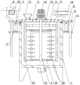
Fig. 1 shows a schematic front sectional structure of an embodiment of the present invention;
fig. 2 is a schematic front view of an embodiment of the present invention;
fig. 3 is a schematic view of a scraper connection structure according to an embodiment of the present invention.
Reference numerals: 1. a stirring tank; 2. a can lid; 3. a jacking mechanism; 4. a stirring rod; 5. a cleaning mechanism; 6. a base plate; 7. a cylinder; 8. a fixing plate; 9. an annular insert block; 10. an annular slot; 11. a feed inlet; 12. a discharge port; 13. a limiting rod; 14. a motor; 15. an electric telescopic rod; 16. a squeegee; 17. an extension hole; 18. an extension rod; 19. fixing the rod; 20. a fan blade; 21. a transparent viewing window.
Detailed Description
The technical solution of the present invention will be further explained with reference to the accompanying drawings and specific embodiments.
Example one
As shown in fig. 1-3, the utility model provides a server cooling oil preparation facilities, include: agitator tank 1, cover 2 are located agitator tank 1 top, and two climbing mechanism 3 are located agitator tank 1 relative position's both sides upper end and are used for driving cover 2, and puddler 4 is located agitator tank 1, is equipped with clearance mechanism 5 on the puddler 4.
Equal horizontal fixedly connected with extension rod 18 in both ends about the one side that two scraper blades 16 are close to each other, the 19 horizontal fixedly connected of a plurality of dead levers are located a plurality of extension rod 18 relative positions respectively in 4 lateral walls of puddler, and extension hole 17 is seted up and is close to extension rod 18 one end in dead lever 19, and extension rod 18 keeps away from 16 one end of scraper blades and all stretches into corresponding extension hole 17 in with extension hole 17 inside wall sliding connection.
The working principle based on the first embodiment is as follows: the coolant oil raw materials that will mix pours into agitator tank 1 from charge door 11 in, drive puddler 4 through motor 14 and rotate, mix the raw materials, in the in-process that puddler 4 rotated the mixture, scraper blade 16 and agitator tank 1 inside wall contactless, the coolant oil raw materials that the mixture was accomplished discharge through discharge gate 12, after the raw materials discharge, drive puddler 4 through motor 14 and carry out high-speed rotation, centrifugal force through high-speed rotation production throws away remaining coolant oil raw materials on puddler 4, then drive scraper blade 16 through electric telescopic handle 15 and remove, make its one side be connected with 1 inside wall contact of agitator tank, then motor 14 drives scraper blade 16 through puddler 4 and carries out slow rotation, strike off remaining raw materials of agitator tank 1 inside wall, then discharge through discharge gate 12, reduce the waste of raw materials, the consumption of cost is reduced, slide in extending hole 17 through extension rod 18 one end, improve the stability of scraper blade 16 horizontal migration, when needing to wash agitator tank 1 inside and puddler 4, drive cover 2 through cylinder 7 and move upward, make cover 2 break away from agitator tank 1 upward while drive agitator tank 4 and improve the stability that the inside wall is taken out, the convenient for the wash-up and take, the efficiency of the convenient for the wash tank is improved, the efficiency of the inner wall of agitator tank 1, the wash-up and wash-up and wash-down of the efficiency of the side of the inner wall of the side of the agitator tank, can.
Example two
As shown in fig. 1 and fig. 2, based on the first embodiment, the utility model provides a server cooling oil preparation device, a plurality of flabellums 20 rotate to be connected on puddler 4.
The transparent observation window 21 is opened at the upper end of one side of the stirring tank 1.
The working principle based on the second embodiment is as follows: when puddler 4 rotated, through the liquid mobility that the cooling oil stirring produced, be convenient for drive flabellum 20 and rotate, the rotation through flabellum 20 is convenient for further stir the cooling oil and mixes, improves the homogeneity that the stirring was mixed, is convenient for carry out real-time observation to the stirring condition of cooling oil in agitator tank 1 through transparent observation window 21.
The above embodiments are merely some preferred embodiments of the present invention, and those skilled in the art can make various alternative modifications and combinations to the above embodiments based on the technical solution of the present invention and the related teachings of the above embodiments.
Claims (6)
1. A server cooling oil production apparatus comprising: agitator tank (1), its characterized in that: agitator tank (1) top is equipped with cover (2), agitator tank (1) relative position's both sides upper end all is equipped with and is used for carrying out driven climbing mechanism (3) to cover (2), be equipped with puddler (4) in agitator tank (1), be equipped with clearance mechanism (5) on puddler (4).
2. The server cooling oil preparation device according to claim 1, wherein the jacking mechanism (3) comprises a bottom plate (6), the bottom plate (6) is fixedly connected to the side wall of the stirring tank (1), a cylinder (7) is fixedly connected to the top surface of the bottom plate (6), a fixed plate (8) is fixedly connected to the side wall of the tank cover (2) above the cylinder (7), the top of the cylinder (7) is fixedly connected to the bottom surface of the corresponding fixed plate (8), an annular insert block (9) is fixedly connected to the bottom surface of the tank cover (2), an annular insert block (10) is arranged below the annular insert block (9) on the top surface of the stirring tank (1), the annular insert block (9) is connected to the annular insert block (10) in an inserting manner, a feed inlet (11) is arranged at one end of the top of the tank cover (2), a discharge outlet (12) is arranged at the middle end of the bottom of the stirring tank (1), control valves are arranged on the discharge outlet (12) and the feed inlet (11), and a limiting rod (13) is vertically fixedly connected to the bottom surface of the cylinder (7) and slidably connected to the bottom plate (6).
3. The server cooling oil preparation device according to claim 1, characterized in that the motor (14) is fixedly connected to the top of the tank cover (2) at the opposite position of the stirring rod (4), the top end of the stirring rod (4) penetrates through the top of the tank cover (2) and is fixedly connected with the output end of the motor (14), the cleaning mechanism (5) comprises two electric telescopic rods (15), the two electric telescopic rods (15) are horizontally and fixedly connected to the top ends of the two sides at the opposite position of the stirring rod (4), and the scraper (16) is vertically and fixedly connected to the sides of the two electric telescopic rods (15) far away from each other.
4. The server cooling oil preparation device according to claim 3, wherein the two scrapers (16) are fixedly connected with an extension rod (18) horizontally on the upper end and the lower end of the side close to each other, the side wall of the stirring rod (4) is fixedly connected with a fixing rod (19) horizontally on the opposite position of the extension rod (18), the fixing rod (19) is provided with an extension hole (17) on the end close to the extension rod (18), and the end of the extension rod (18) far away from the scrapers (16) is slidably connected with the inner side wall of the extension hole (17).
5. The server cooling oil preparation device according to claim 1, wherein a plurality of fan blades (20) are rotatably connected to the stirring rod (4).
6. The server cooling oil preparation device according to claim 1, wherein a transparent observation window (21) is formed at the upper end of one side of the stirring tank (1).
Priority Applications (1)
| Application Number | Priority Date | Filing Date | Title |
|---|---|---|---|
| CN202223019456.1U CN218688728U (en) | 2022-11-14 | 2022-11-14 | Server cooling oil preparation facilities |
Applications Claiming Priority (1)
| Application Number | Priority Date | Filing Date | Title |
|---|---|---|---|
| CN202223019456.1U CN218688728U (en) | 2022-11-14 | 2022-11-14 | Server cooling oil preparation facilities |
Publications (1)
| Publication Number | Publication Date |
|---|---|
| CN218688728U true CN218688728U (en) | 2023-03-24 |
Family
ID=85617821
Family Applications (1)
| Application Number | Title | Priority Date | Filing Date |
|---|---|---|---|
| CN202223019456.1U Active CN218688728U (en) | 2022-11-14 | 2022-11-14 | Server cooling oil preparation facilities |
Country Status (1)
| Country | Link |
|---|---|
| CN (1) | CN218688728U (en) |
Cited By (1)
| Publication number | Priority date | Publication date | Assignee | Title |
|---|---|---|---|---|
| CN117772732A (en) * | 2024-02-23 | 2024-03-29 | 江苏金利马重工机械制造有限公司 | Dirt treatment device for stirring tank |
-
2022
- 2022-11-14 CN CN202223019456.1U patent/CN218688728U/en active Active
Cited By (1)
| Publication number | Priority date | Publication date | Assignee | Title |
|---|---|---|---|---|
| CN117772732A (en) * | 2024-02-23 | 2024-03-29 | 江苏金利马重工机械制造有限公司 | Dirt treatment device for stirring tank |
Similar Documents
| Publication | Publication Date | Title |
|---|---|---|
| CN218688728U (en) | Server cooling oil preparation facilities | |
| CN207324625U (en) | A kind of subgrade construction builds mixer | |
| CN219518680U (en) | Concrete admixture heating and stirring device | |
| CN112058149A (en) | A soil agitating unit for polluting soil and administer | |
| CN213055373U (en) | Grouting device | |
| CN212758078U (en) | Yoghourt emulsifying device | |
| CN210522441U (en) | Plastic course substrate is with mixing agitated vessel | |
| CN211104761U (en) | Take cleaning function's mixer | |
| CN220919027U (en) | Stirring mechanism of ceramic pigment stirrer | |
| CN212595150U (en) | Continuous type device of beating sugar | |
| CN218221164U (en) | Extraction precipitation secondary knockout drum | |
| CN220840834U (en) | Mortar mixer with self-cleaning function | |
| CN218339627U (en) | Vacuum double-shaft stirrer | |
| CN220313754U (en) | Automatic mixer for cement paste | |
| CN221492264U (en) | Vacuum emulsifying device for body milk production | |
| CN214233601U (en) | Full-automatic stirring equipment | |
| CN221271588U (en) | Stirring device for cement paste | |
| CN218890549U (en) | A retort for papermaking auxiliary agent | |
| CN220940547U (en) | Water-based adhesive production device | |
| CN216321371U (en) | Asphalt mixture mixing machine | |
| CN212370053U (en) | A soil agitating unit for polluting soil and administer | |
| CN220835582U (en) | Water purifying agent production facility | |
| CN216396082U (en) | Coating stirrer | |
| CN219765148U (en) | Detergent mixing device | |
| CN214026381U (en) | Slurry stirring machine convenient for feeding |
Legal Events
| Date | Code | Title | Description |
|---|---|---|---|
| GR01 | Patent grant | ||
| GR01 | Patent grant |