CN218623500U - Building construction bearing structure - Google Patents
Building construction bearing structure Download PDFInfo
- Publication number
- CN218623500U CN218623500U CN202222973739.3U CN202222973739U CN218623500U CN 218623500 U CN218623500 U CN 218623500U CN 202222973739 U CN202222973739 U CN 202222973739U CN 218623500 U CN218623500 U CN 218623500U
- Authority
- CN
- China
- Prior art keywords
- sleeve
- connecting plate
- base
- rigid coupling
- fixedly connected
- Prior art date
- Legal status (The legal status is an assumption and is not a legal conclusion. Google has not performed a legal analysis and makes no representation as to the accuracy of the status listed.)
- Active
Links
Images


Abstract
The utility model discloses a construction bearing structure, include: the lifting platform mechanism comprises a base, a connecting plate and a lifting part, the connecting plate is positioned above the base, the lifting part is positioned between the base and the connecting plate, and two ends of the lifting part are fixedly connected with the base and the connecting plate respectively; the two auxiliary supporting components are respectively positioned on two sides of the lifting part, the two auxiliary supporting components are both positioned between the base and the connecting plate, and two ends of each auxiliary supporting component are respectively fixedly connected with the base and the connecting plate; pipeline fixed establishment, pipeline fixed establishment include track and clamping part, and the track rigid coupling is on the connecting plate top, and the clamping part is provided with a plurality of, and a plurality of clamping part is all spacing to be slipped on the track. The utility model discloses a set up a plurality of clamping parts and can support many pipelines simultaneously for the efficiency that the pipeline was erect, the interval of clamping part is adjustable simultaneously, can satisfy the condition that different pipelines erect.
Description
Technical Field
The utility model relates to a construction equipment technical field especially relates to a construction bearing structure.
Background
A plurality of pipelines need to be erected on the roof in the building construction process such as a building, and the pipelines erected on the roof need to be supported by using a supporting tool in the construction process, so that the pipelines are kept at a certain height position to facilitate construction operation of constructors.
However, the existing supporting structure can only support one pipeline, and a plurality of pipelines need to be erected on a roof in actual construction, and the existing supporting structure obviously cannot meet the purpose that a plurality of pipelines support simultaneously, so that the construction efficiency of the supporting structure is low.
Therefore, it is desirable to design a supporting structure for building construction to solve the above problems.
SUMMERY OF THE UTILITY MODEL
The utility model aims at providing a construction bearing structure, include:
the lifting platform mechanism comprises a base, a connecting plate and a lifting part, the connecting plate is positioned above the base, the lifting part is positioned between the base and the connecting plate, and two ends of the lifting part are fixedly connected with the base and the connecting plate respectively;
the two auxiliary supporting assemblies are respectively positioned on two sides of the lifting part, the two auxiliary supporting assemblies are both positioned between the base and the connecting plate, and two ends of each auxiliary supporting assembly are respectively fixedly connected with the base and the connecting plate;
pipeline fixed establishment, pipeline fixed establishment includes track and clamping part, the track rigid coupling is in the connecting plate top, the clamping part is provided with a plurality of, and is a plurality of the equal spacing sliding joint of clamping part is in on the track.
Preferably, the clamping part includes slider, fixed block and clamping component, the slider cunning is in on the track, slider one side spiro union has adjusting bolt, adjusting bolt is used for restricting the slider is in position on the track, the fixed block rigid coupling is in the slider top, run through on the fixed block and seted up the U-shaped through-hole, clamping component installs on the fixed block.
Preferably, clamping component includes briquetting, adjusting screw and gag lever post, the briquetting is located the U-shaped through-hole, the arc is sunken has been seted up to the briquetting bottom, the briquetting top is rotated and is connected with adjusting screw, the terminal screw thread of adjusting screw runs through the fixed block, the adjusting screw both sides all are provided with the gag lever post, the gag lever post rigid coupling is in the briquetting top, the gag lever post end slides and runs through the fixed block.
Preferably, a rubber pad is fixedly connected in the arc-shaped recess.
Preferably, lift portion includes second sleeve and threaded rod, the threaded rod rigid coupling is in the connecting plate bottom, the spacing slip cover of second sleeve is established on the threaded rod, second sleeve bottom with the base rigid coupling, second sleeve internal rotation is connected with the worm wheel, the worm wheel threaded sleeve is established on the threaded rod, second sleeve outer wall rigid coupling has the box, the internal rotation of box is connected with the worm, the box outer wall rotates and is connected with the rocking handle, the rocking handle with the coaxial rigid coupling of worm, the opening has been seted up to second sleeve outer wall, the opening with worm wheel position looks adaptation, the worm passes through the opening runs through the second sleeve with the worm wheel meshes mutually, two the auxiliary stay subassembly is located the both sides of second sleeve.
Preferably, the inner wall of the second sleeve is fixedly connected with a limiting block, the limiting block is positioned above the worm wheel, a limiting groove matched with the limiting block is formed in the outer wall of the threaded rod, and the limiting block is in sliding connection with the limiting groove.
Preferably, the outer wall of the bottom of the second sleeve is fixedly connected with a plurality of reinforcing ribs, and the plurality of reinforcing ribs are fixedly connected with the base.
Preferably, the auxiliary supporting component comprises a first sleeve and a sliding rod, two the sliding rod is respectively located on two sides of the second sleeve, the sliding rod is fixedly connected to the bottom end of the connecting plate, the sliding sleeve is arranged on the sliding rod and provided with the first sleeve, and the bottom end of the first sleeve is fixedly connected to the base.
The utility model discloses a following technological effect:
set up a plurality of bearing structure according to the length of pipeline during the use, erect the interval that needs adjusted a plurality of clamping parts according to the pipeline, pass the clamping part with the pipeline after adjusting, promote the pipeline to suitable height and realize supporting through the portion that goes up and down, carry out pipeline erection work, erect the process and gather and gradually remove bearing structure. The utility model discloses a set up a plurality of clamping parts and can support many pipelines simultaneously for the efficiency that the pipeline was erect, the interval of clamping part is adjustable simultaneously, can satisfy the condition that different pipelines erect.
Drawings
In order to more clearly illustrate the embodiments of the present invention or the technical solutions in the prior art, the drawings required to be used in the embodiments will be briefly described below, and it is obvious that the drawings in the following description are only some embodiments of the present invention, and for those skilled in the art, other drawings can be obtained according to these drawings without inventive labor.
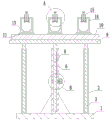
FIG. 1 is a front view of a construction support structure;
FIG. 2 is a schematic structural view of a construction support structure;
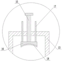
FIG. 3 is an enlarged view of A in FIG. 2;
FIG. 4 is an enlarged view of B in FIG. 2;
wherein, 1, a base; 2. a first sleeve; 3. a slide bar; 4. a box body; 5. a rocking handle; 6. a second sleeve; 7. a reinforcing rib plate; 8. a threaded rod; 9. a connecting plate; 10. a track; 11. a slider; 12. adjusting the bolt; 13. a fixed block; 14. a U-shaped through hole; 15. adjusting the screw rod; 16. briquetting; 17. a limiting rod; 18. a rubber pad; 19. a worm gear; 20. a limiting block; 21. a limiting groove; 22. a worm.
Detailed Description
The technical solution in the embodiments of the present invention will be described clearly and completely with reference to the accompanying drawings in the embodiments of the present invention, and it is obvious that the described embodiments are only partial embodiments of the mechanism of the present invention, not full embodiments of the mechanism. Based on the embodiments in the present invention, all other embodiments obtained by a person skilled in the art without creative work belong to the protection scope of the present invention.
In order to make the aforementioned objects, features and advantages of the present invention more comprehensible, the present invention is described in detail with reference to the accompanying drawings and the following detailed description.
The utility model provides a construction bearing structure, include:
the lifting platform mechanism comprises a base 1, a connecting plate 9 and a lifting part, wherein the connecting plate 9 is positioned above the base 1, the lifting part is positioned between the base 1 and the connecting plate 9, and two ends of the lifting part are fixedly connected with the base 1 and the connecting plate 9 respectively;
the two auxiliary supporting components are respectively positioned on two sides of the lifting part, the two auxiliary supporting components are both positioned between the base 1 and the connecting plate 9, and two ends of each auxiliary supporting component are fixedly connected with the base 1 and the connecting plate 9 respectively;
pipeline fixed establishment, pipeline fixed establishment include track 10 and clamping part, and the track 10 rigid coupling is on connecting plate 9 tops, and the clamping part is provided with a plurality of, and a plurality of clamping part is all spacing sliding connection on track 10.
Further, the clamping part comprises a sliding block 11, a fixing block 13 and a clamping assembly, the sliding block 11 is connected to the track 10 in a sliding mode, an adjusting bolt 12 is connected to one side of the sliding block 11 in a threaded mode, the adjusting bolt 12 is used for limiting the position of the sliding block 11 on the track 10, the fixing block 13 is fixedly connected to the top end of the sliding block 11, a U-shaped through hole 14 is formed in the fixing block 13 in a penetrating mode, and the clamping assembly is installed on the fixing block 13.
When using, twist adjusting bolt 12, make adjusting bolt 12's end no longer butt track 10, slider 11 can slide on track 10 this moment, erect the interval of a plurality of clamping parts according to a plurality of pipelines and need adjust, make adjusting bolt 12 again and track 10 butt after the regulation is accomplished, just can no longer slide slider 11, the pipeline that will wait to erect passes from U-shaped through-hole 14, then fixes at U-shaped through-hole 14 through clamping components, the realization is to the support of pipeline.
Further, clamping component includes briquetting 16, adjusting screw 15 and gag lever post 17, and briquetting 16 is located U-shaped through- hole 14, and 16 bottoms of briquetting have been seted up the arc sunken, and 16 tops of briquetting rotate to be connected with adjusting screw 15, and 15 terminal threads of adjusting screw run through fixed block 13, and 15 both sides of adjusting screw all are provided with gag lever post 17, and gag lever post 17 rigid coupling is on 16 tops of briquetting, and the gag lever post 17 end slides and runs through fixed block 13.
The adjusting screw 15 is rotated, due to the limiting effect of the limiting rod 17, the pressing block 16 can be adjusted to move up and down by rotating the adjusting screw 15, and when the pressing block 16 needs to be pressed on the pipeline, the pressing block 16 is contacted with the pipeline by rotating the adjusting screw 15.
Further, in order to increase the friction force between the pressing block 16 and the pipeline, the pressing block 16 can more firmly fix the pipeline in the U-shaped through hole 14, and a rubber pad 18 is fixedly connected in the arc-shaped recess.
Further, lift portion includes second sleeve 6 and threaded rod 8, 8 rigid couplings of threaded rod are in the 9 bottoms of connecting plate, the spacing slip cover of second sleeve 6 is established on threaded rod 8, 6 bottoms of second sleeve and 1 rigid coupling of base, 6 internal rotations of second sleeve are connected with worm wheel 19, 19 threaded couplings of worm wheel are established on threaded rod 8, 6 outer wall rigid couplings of second sleeve have box 4, 4 internal rotations of box are connected with worm 22, 4 outer walls of box rotate and are connected with rocking handle 5, rocking handle 5 and the coaxial rigid coupling of worm 22, 6 outer walls of second sleeve have seted up the opening, opening and 19 position looks adaptations of worm wheel, worm 22 runs through second sleeve 6 through the opening and meshes with worm wheel 19 mutually, two auxiliary support assembly are located the both sides of second sleeve 6.
Furthermore, the inner wall of the second sleeve 6 is fixedly connected with a limiting block 20, the limiting block 20 is positioned on the outer wall of the threaded rod 8 above the worm wheel 19, a limiting groove 21 matched with the limiting block 20 is formed in the outer wall of the threaded rod, and the limiting block 20 is in sliding connection with the limiting groove 21.
Rotate rocking handle 5, rocking handle 5 drives worm 22 and rotates, and worm 22 drives worm wheel 19 and rotates, because threaded rod 8 and 6 spacing sliding connection of second sleeve when worm wheel 19 rotates, consequently can drive threaded rod 8 up-and-down motion, and then realize the regulation to connecting plate 9 height, make the pipeline of installation can rise to suitable height on the clamping part, conveniently erect the pipeline, through worm wheel 19, worm 22's reverse self-locking function, ensured the reliability of lift portion.
Further, a plurality of reinforcing rib plates 7 are fixedly connected to the outer wall of the bottom of the second sleeve 6, and the plurality of reinforcing rib plates 7 are fixedly connected with the base 1.
Further, the auxiliary supporting assembly comprises a first sleeve 2 and a sliding rod 3, the two sliding rods 3 are respectively located on two sides of a second sleeve 6, the sliding rod 3 is fixedly connected to the bottom end of a connecting plate 9, the sliding sleeve 3 is sleeved with the first sleeve 2 in a sliding mode, and the bottom end of the first sleeve 2 is fixedly connected with the base 1.
The using method comprises the following steps: set up a plurality of bearing structure according to the length of pipeline, erect the interval that needs adjusted a plurality of clamping parts according to the pipeline, pass the clamping part with the pipeline after adjusting, promote the pipeline to suitable height and realize supporting through the portion that goes up and down, carry out pipeline erection work, the erection process gathers and progressively removes bearing structure. The utility model discloses a set up a plurality of clamping parts and can support many pipelines simultaneously for the efficiency that the pipeline was erect, the interval of clamping part is adjustable simultaneously, can satisfy the condition that different pipelines erect.
In the description of the present invention, it is to be understood that the terms "longitudinal", "lateral", "up", "down", "front", "back", "left", "right", "vertical", "horizontal", "top", "bottom", "inner", "outer", and the like indicate orientations or positional relationships based on those shown in the drawings, and are only for convenience of description of the present invention, and do not indicate or imply that the device or component being referred to must have a particular orientation, be constructed and operated in a particular orientation, and therefore, should not be construed as limiting the present invention.
The above-mentioned embodiments are only intended to describe the preferred embodiments of the present invention, but not to limit the scope of the present invention, and those skilled in the art should also be able to make various modifications and improvements to the technical solution of the present invention without departing from the spirit of the present invention, and all such modifications and improvements are intended to fall within the scope of the present invention as defined in the appended claims.
Claims (8)
1. A construction support structure, comprising:
the lifting platform mechanism comprises a base (1), a connecting plate (9) and a lifting part, wherein the connecting plate (9) is positioned above the base (1), the lifting part is positioned between the base (1) and the connecting plate (9), and two ends of the lifting part are fixedly connected with the base (1) and the connecting plate (9) respectively;
the two auxiliary supporting assemblies are respectively positioned on two sides of the lifting part, the two auxiliary supporting assemblies are respectively positioned between the base (1) and the connecting plate (9), and two ends of each auxiliary supporting assembly are fixedly connected with the base (1) and the connecting plate (9) respectively;
pipeline fixed establishment, pipeline fixed establishment includes track (10) and clamping part, track (10) rigid coupling is in connecting plate (9) top, the clamping part is provided with a plurality of, and is a plurality of the equal spacing sliding joint of clamping part is in on track (10).
2. The construction support structure of claim 1, wherein: the clamping part comprises a sliding block (11), a fixed block (13) and a clamping assembly, the sliding block (11) is connected with the rail (10) in a sliding mode, an adjusting bolt (12) is screwed on one side of the sliding block (11), the adjusting bolt (12) is used for limiting the position of the sliding block (11) on the rail (10), the fixed block (13) is fixedly connected to the top end of the sliding block (11), a U-shaped through hole (14) is formed in the fixed block (13) in a penetrating mode, and the clamping assembly is installed on the fixed block (13).
3. The construction support structure of claim 2, wherein: clamping component includes briquetting (16), adjusting screw (15) and gag lever post (17), briquetting (16) are located U-shaped through-hole (14), the arc has been seted up to briquetting (16) bottom and has been sunken, briquetting (16) top is rotated and is connected with adjusting screw (15), adjusting screw (15) end screw thread runs through fixed block (13), adjusting screw (15) both sides all are provided with gag lever post (17), gag lever post (17) rigid coupling is in briquetting (16) top, gag lever post (17) end slip runs through fixed block (13).
4. A construction support structure according to claim 3, wherein: a rubber pad (18) is fixedly connected in the arc-shaped recess.
5. The construction support structure of claim 1, wherein: the lift portion includes second sleeve (6) and threaded rod (8), threaded rod (8) rigid coupling is in connecting plate (9) bottom, the spacing slip cap of second sleeve (6) is established on threaded rod (8), second sleeve (6) bottom with base (1) rigid coupling, second sleeve (6) internal rotation is connected with worm wheel (19), worm wheel (19) threaded sleeve is established on threaded rod (8), second sleeve (6) outer wall rigid coupling has box (4), box (4) internal rotation is connected with worm (22), box (4) outer wall rotates and is connected with rocking handle (5), rocking handle (5) with the coaxial rigid coupling of worm (22), the opening has been seted up to second sleeve (6) outer wall, the opening with worm wheel (19) position looks adaptation, worm (22) pass through the opening runs through second sleeve (6) with worm wheel (19) mesh mutually, two supplementary supporting component is located the both sides of second sleeve (6).
6. The construction support structure of claim 5, wherein: second sleeve (6) inner wall rigid coupling has stopper (20), stopper (20) are located the top of worm wheel (19) threaded rod (8) outer wall seted up with spacing groove (21) of stopper (20) looks adaptation, stopper (20) with spacing groove (21) sliding connection.
7. The construction support structure of claim 5, wherein: the outer wall of the bottom of the second sleeve (6) is fixedly connected with a plurality of reinforcing rib plates (7), and the plurality of reinforcing rib plates (7) are fixedly connected with the base (1).
8. The construction support structure of claim 5, wherein: supplementary supporting component includes first sleeve (2) and slide bar (3), two slide bar (3) are located respectively the both sides of second sleeve (6), slide bar (3) rigid coupling is in connecting plate (9) bottom, sliding sleeve is equipped with on slide bar (3) first sleeve (2), first sleeve (2) bottom with base (1) rigid coupling.
Priority Applications (1)
| Application Number | Priority Date | Filing Date | Title |
|---|---|---|---|
| CN202222973739.3U CN218623500U (en) | 2022-11-07 | 2022-11-07 | Building construction bearing structure |
Applications Claiming Priority (1)
| Application Number | Priority Date | Filing Date | Title |
|---|---|---|---|
| CN202222973739.3U CN218623500U (en) | 2022-11-07 | 2022-11-07 | Building construction bearing structure |
Publications (1)
| Publication Number | Publication Date |
|---|---|
| CN218623500U true CN218623500U (en) | 2023-03-14 |
Family
ID=85422889
Family Applications (1)
| Application Number | Title | Priority Date | Filing Date |
|---|---|---|---|
| CN202222973739.3U Active CN218623500U (en) | 2022-11-07 | 2022-11-07 | Building construction bearing structure |
Country Status (1)
| Country | Link |
|---|---|
| CN (1) | CN218623500U (en) |
Cited By (1)
| Publication number | Priority date | Publication date | Assignee | Title |
|---|---|---|---|---|
| CN116498095A (en) * | 2023-06-26 | 2023-07-28 | 山西八建集团有限公司 | Supporting mechanism for assisting installation of building conversion truss |
-
2022
- 2022-11-07 CN CN202222973739.3U patent/CN218623500U/en active Active
Cited By (2)
| Publication number | Priority date | Publication date | Assignee | Title |
|---|---|---|---|---|
| CN116498095A (en) * | 2023-06-26 | 2023-07-28 | 山西八建集团有限公司 | Supporting mechanism for assisting installation of building conversion truss |
| CN116498095B (en) * | 2023-06-26 | 2023-09-26 | 山西八建集团有限公司 | Supporting mechanism for assisting installation of building conversion truss |
Similar Documents
| Publication | Publication Date | Title |
|---|---|---|
| CN218623500U (en) | Building construction bearing structure | |
| CN207829458U (en) | A kind of construction roof beam structure | |
| CN112942827A (en) | Stupefied connection structure of steel formwork frame back of body for building | |
| CN217112448U (en) | Electronic component detection device | |
| CN216045790U (en) | Auxiliary device for pipeline installation and connection | |
| CN213361311U (en) | High-strength steel support convenient to install | |
| CN115609214A (en) | Breast board assembling and welding table for breast board type semi-trailer | |
| CN213915180U (en) | Quick belt cleaning device of building board that building engineering used | |
| CN114592633A (en) | European style truss integral structure system installation structure and European style truss system installation method | |
| CN211143839U (en) | Assembled side top supporting device | |
| CN218843845U (en) | Anti-deformation device for construction of concrete filled steel tubular column | |
| CN219865154U (en) | Be used for operation tunnel pipeline installing support | |
| CN220058297U (en) | General connecting piece of steel structure frame | |
| CN217924412U (en) | Energy-concerving and environment-protective steel construction bracket that stability is strong | |
| CN217379290U (en) | Steel construction interfacing apparatus for construction | |
| CN220565705U (en) | Support knot of post-cast strip template | |
| CN215153444U (en) | Mathematics drawing board connecting device with flexible function | |
| CN215357016U (en) | Comprehensive pipe rack information construction management and control operation platform | |
| CN220014049U (en) | Assembled steel structure connecting piece | |
| CN216157245U (en) | Building structure's reinforcement connecting device | |
| CN213318688U (en) | Electronic device welding combination tool | |
| CN218668494U (en) | Aluminum alloy template installation strutting arrangement | |
| CN220320495U (en) | River-crossing bracket for rain sewage pipeline | |
| CN217632285U (en) | Independent installation guide rail system for top drive equipment | |
| CN219138326U (en) | Automatic positioning and fastening device for jacking of frame body |
Legal Events
| Date | Code | Title | Description |
|---|---|---|---|
| GR01 | Patent grant | ||
| GR01 | Patent grant |