CN218601450U - Full-automatic high-voltage wire harness detection machine convenient for wire harness propulsion - Google Patents
Full-automatic high-voltage wire harness detection machine convenient for wire harness propulsion Download PDFInfo
- Publication number
- CN218601450U CN218601450U CN202222932170.6U CN202222932170U CN218601450U CN 218601450 U CN218601450 U CN 218601450U CN 202222932170 U CN202222932170 U CN 202222932170U CN 218601450 U CN218601450 U CN 218601450U
- Authority
- CN
- China
- Prior art keywords
- propelling movement
- wire harness
- pencil
- loading board
- box
- Prior art date
- Legal status (The legal status is an assumption and is not a legal conclusion. Google has not performed a legal analysis and makes no representation as to the accuracy of the status listed.)
- Active
Links
Images


Abstract
The utility model provides a full-automatic high-pressure pencil detects machine convenient to pencil impels, including the lift loading board, the propelling movement baffle-box, the stand, adjusting screw, the propelling movement gyro wheel, fixed bolster and buffering propelling movement rubber roll, the propelling movement baffle-box is installed to the stand upside, propelling movement baffle-box internally mounted has buffering propelling movement rubber roll, crossbeam backup pad downside is provided with the lift loading board, two sets of adjusting screw are installed to lift loading board up end left and right sides symmetry, the motor is installed to lift loading board upside, driving pulley is installed to the motor front side, the fixed bolster is installed to lift loading board downside, fixed bolster internally mounted has the propelling movement gyro wheel, this design has solved inside original full-automatic high-pressure pencil detects machine needs artifical manual work to impel the high-pressure pencil inside the detection machine, the operation is convenient inadequately, artifical intensity of labour is big, the pencil impels the not good problem of effect, the utility model discloses rational in infrastructure, the pencil of being convenient for impels, easy operation is convenient, labor intensity has alleviateed staff's working strength.
Description
Technical Field
The utility model relates to a full-automatic high-pressure pencil detects machine convenient to pencil impels belongs to high-pressure pencil and detects technical field.
Background
The wire harness is the totality of equipment providing services for a certain load source group, such as a trunk line, a switching device, a control system and the like, and the basic research content of the telephone traffic theory is to research the relationship among telephone traffic, call loss and wire harness capacity, so the wire harness is an important basic concept in the telephone traffic theory. In the production process of high-voltage wire harness, the full-automatic high-voltage wire harness detection machine is often used for detecting the wire harness, so that the phenomena of short circuit, open circuit, mismatch and the like can be found as early as possible, but the existing full-automatic high-voltage wire harness detection machine is in the practical process, the high-voltage wire harness needs to be manually pushed into the detection machine, the operation is not convenient and fast enough, the labor intensity is high, the wire harness pushing effect is not good enough, and the problem that the wire harness pushing is convenient to push is urgently needed to solve.
SUMMERY OF THE UTILITY MODEL
Not enough to prior art exists, the utility model aims at providing a full-automatic high-pressure pencil detects machine convenient to pencil impels to solve the problem that proposes in the above-mentioned background art, the utility model discloses rational in infrastructure, the pencil of being convenient for impels, and easy operation is convenient, has alleviateed staff's intensity of labour.
In order to achieve the above purpose, the present invention is realized by the following technical solution: the utility model provides a full-automatic high-pressure pencil detects machine convenient to pencil impels, is including detecting quick-witted main part, high-pressure pencil, testing platform, electric cabinet, universal movable wheel and pencil push mechanism, the electric cabinet upside is provided with the detection quick-witted main part, testing platform is installed to the electric cabinet up end, the universal movable wheel is installed to the electric cabinet downside, the testing platform upside is provided with high-pressure pencil, the electric cabinet left side is provided with pencil push mechanism, pencil push mechanism includes crossbeam backup pad, fixed branch, lift loading board, propelling movement baffle-box, stand, bed plate, adjusting screw, motor, driving pulley, propelling movement gyro wheel, driven pulleys, fixed bolster and buffering propelling movement rubber roll, the bed plate is provided with the electric cabinet left side, the stand is installed to the bed plate upside, the propelling movement case is installed to the stand upside, propelling movement baffle-box internally mounted has the propelling movement, four turning positions of propelling movement baffle-box up end are installed four groups of fixed branch, the crossbeam backup pad is installed to the fixed branch upside, the crossbeam backup pad downside is provided with the lift loading board, two sets of adjusting screw are installed to lift loading board up end left and right sides symmetry, the motor front side installs four groups of driving movement rubber roll fixed support, propelling movement gyro wheel.
Furthermore, the pushing buffer box is fixedly connected with the stand column in a welding mode, reinforcing rib plates are arranged at the joint of the stand column and the pushing buffer box and the joint of the base plate, and a rubber foot pad is arranged on the lower end face of the base plate.
Furthermore, a hand wheel handle is installed at the upper end of the adjusting screw rod, a fixed shaft seat is installed at the joint of the adjusting screw rod and the lifting bearing plate, and the adjusting screw rod is rotatably connected with the fixed shaft seat.
Further, the propelling movement gyro wheel is provided with two sets ofly, two sets of propelling movement gyro wheel symmetry sets up in lift loading board downside, and two sets of driven pulleys is all installed to propelling movement gyro wheel front side, driven pulleys and driving pulley junction are equipped with driving belt.
Furthermore, an arc-shaped groove is formed in the pushing roller, and a rubber sleeve is sleeved on the surface of the arc-shaped groove.
Further, buffering propelling movement rubber roll is provided with four groups, and four groups buffering propelling movement rubber roll specification is the same, four groups buffering propelling movement rubber roll equidistance is installed inside the propelling movement baffle-box.
The utility model has the advantages that: the utility model discloses a full-automatic high-pressure pencil detects machine convenient to pencil impels, because of the utility model discloses added crossbeam backup pad, fixed branch, lift loading board, propelling movement baffle-box, stand, bed plate, adjusting screw, motor, driving pulley, propelling movement gyro wheel, driven pulleys, fixed bolster and buffering propelling movement rubber roll, this design pencil of being convenient for impels, easy operation is convenient, the intensity of labour who has alleviateed personnel, it needs artifical manual to impel the detection machine with high-pressure pencil inside to have solved original full-automatic high-pressure pencil detects machine, it is convenient inadequately to operate, artifical intensity of labour is big, the pencil impels the problem that the effect is not good enough, improved the utility model discloses a pencil detects the convenience.
Drawings
Other features, objects and advantages of the invention will become more apparent upon reading of the detailed description of non-limiting embodiments with reference to the following drawings:
fig. 1 is a schematic structural view of a full-automatic high-voltage wire harness detection machine convenient for wire harness propulsion according to the present invention;
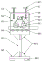
fig. 2 is a schematic structural view of a wire harness pushing mechanism in the full-automatic high-voltage wire harness detecting machine convenient for wire harness pushing of the present invention;
fig. 3 is a front sectional view of a wire harness pushing mechanism in the full-automatic high-voltage wire harness detecting machine convenient for wire harness pushing of the utility model;
fig. 4 is a left side view structural diagram of a wire harness pushing mechanism in the full-automatic high-voltage wire harness detecting machine convenient for wire harness pushing of the utility model;
in the figure: 1-detector main body, 2-high voltage wire harness, 3-detection platform, 4-electric cabinet, 5-universal moving wheel, 6-wire harness pushing mechanism, 61-beam supporting plate, 62-fixed supporting rod, 63-lifting bearing plate, 64-pushing buffer box, 65-upright post, 66-base plate, 67-adjusting screw, 68-motor, 69-driving pulley, 610-pushing roller, 611-driven pulley, 612-fixed bracket, 613-buffering pushing rubber roller, 651-reinforcing rib plate, 661-rubber foot pad, 671-hand wheel handle, 672-fixed shaft seat, 691-transmission belt and 6101-rubber sheath.
Detailed Description
In order to make the technical means, creation features, achievement purposes and functions of the present invention easy to understand, the present invention is further described below with reference to the following embodiments.
Referring to fig. 1-4, the present invention provides a technical solution: the utility model provides a full-automatic high-pressure pencil detects machine convenient to pencil impels, is including detecting quick-witted main part 1, high-pressure pencil 2, testing platform 3, electric cabinet 4, universal removal wheel 5 and pencil push mechanism 6, and 4 upsides of electric cabinet are provided with and detect quick-witted main part 1, and testing platform 3 is installed to 4 up ends of electric cabinet, and universal removal wheel 5 is installed to 4 downside of electric cabinet, and 3 upsides of testing platform are provided with high-pressure pencil 2, and 4 left sides of electric cabinet are provided with pencil push mechanism 6.
The wire harness pushing mechanism 6 comprises a beam supporting plate 61, fixing support rods 62, a lifting bearing plate 63, a pushing buffer box 64, stand columns 65, a base plate 66, adjusting screws 67, a motor 68, a driving pulley 69, pushing rollers 610, a driven pulley 611, a fixing support 612 and a buffering pushing rubber roll 613, wherein the base plate 66 is provided with the left side of an electric cabinet 4, the stand columns 65 are installed on the upper side of the base plate 66, the pushing buffer box 64 is installed on the upper side of the stand columns 65, the buffering pushing rubber roll 613 is installed inside the pushing buffer box 64, four groups of fixing support rods 62 are installed at four corner positions of the upper end face of the pushing buffer box 64, the beam supporting plate 61 is installed on the upper side of the fixing support rods 62, the lifting bearing plate 63 is arranged on the lower side of the beam supporting plate 61, two groups of adjusting screws 67 are symmetrically installed on the left side and the right side of the upper end face of the lifting bearing plate 63, the motor 68 is installed on the upper side of the lifting bearing plate 63, the driving pulley 69 is installed on the front side of the motor 68, the fixing support 612 is installed on the lower side of the fixing support plate 63, the fixing support 612 is installed inside the pushing rollers 610, the pushing rollers 610 is installed on the front side of the pushing rollers, the front side of the pushing rollers 611, and the driving rollers, the wire harness pushing rollers are convenient and fast to push wire harness pushing work, and convenient to push the high-strength, and rapid detection machine, and rapid to use, and rapid detection machine, and convenient to push the high-labor intensity is not enough.
Propelling movement baffle-box 64 all installs deep floor 651 through welding mode and stand 65 fixed connection, stand 65 and propelling movement baffle-box 64 junction and bed plate 66 junction, and the terminal surface mounting has rubber foot pad 661 under the bed plate 66, and this design has improved the structure steadiness of junction through the deep floor 651 that sets up.
The push rollers 610 are provided with two sets, the two sets of push rollers 610 are symmetrically arranged on the lower side of the lifting bearing plate 63, the driven pulleys 611 are arranged on the front sides of the two sets of push rollers 610, a transmission belt 691 is arranged at the joint of the driven pulleys 611 and the driving pulley 69, and the driven pulleys 611 are driven to rotate through the transmission belt 691.
The inside arc recess of having seted up of propelling movement gyro wheel 610, and arc recess surface cover is equipped with rubber wrap 6101, and the arc recess that this design is convenient for make propelling movement gyro wheel 610 surface can close the laminating with high-pressure pencil 2 through the arc recess that sets up, has boosted the frictional force of contact surface through the rubber wrap 6101 that sets up simultaneously, has improved the non-skid property of contact surface.
The four groups of buffer pushing rubber rollers 613 are arranged, the specifications of the four groups of buffer pushing rubber rollers 613 are the same, the four groups of buffer pushing rubber rollers 613 are equidistantly arranged inside the pushing buffer box 64, and the design improves the pushing smoothness of the high-voltage wire harness 2 through the four groups of buffer pushing rubber rollers 613.
As an embodiment of the present invention: when the high-voltage wiring harness 2 needs to be pushed, a worker firstly places the device on the left side of the electric cabinet 4, then connects the motor 68 with an external controller through a wire, then places the high-voltage wiring harness 2 on the upper sides of the four groups of buffer pushing rubber rollers 613, rotates the adjusting screw 67 through the hand wheel handle 671, drives the lifting bearing plate 63 to move downwards through the adjusting screw 67, enables the two groups of pushing rollers 610 to be clamped and attached to the surface of the high-voltage wiring harness 2, then starts the motor 68 through an external power supply, drives the driving pulley 69 to rotate through the motor 68, drives the driven pulley 611 to rotate through the transmission belt 691, drives the pushing rollers 610 to rotate through the driven pulley 611, pushes the high-voltage wiring harness 2 to the right side through the rotation of the pushing rollers 610, further pushes the high-voltage wiring harness 2 onto the detection platform 3, and then detects the high-voltage wiring harness 2 through the detection machine main body 1, thereby completing the automatic pushing operation of the high-voltage wiring harness 2.
The basic principles and the main features of the invention and the advantages of the invention have been shown and described above, it will be evident to those skilled in the art that the invention is not limited to the details of the foregoing illustrative embodiments, but that the invention may be embodied in other specific forms without departing from the spirit or essential characteristics of the invention. The present embodiments are therefore to be considered in all respects as illustrative and not restrictive, the scope of the invention being indicated by the appended claims rather than by the foregoing description, and all changes which come within the meaning and range of equivalency of the claims are therefore intended to be embraced therein. Any reference sign in a claim should not be construed as limiting the claim concerned.
Furthermore, it should be understood that although the present description refers to embodiments, not every embodiment may contain only a single embodiment, and such description is for clarity only, and those skilled in the art should integrate the description, and the embodiments may be combined as appropriate to form other embodiments understood by those skilled in the art.
Claims (6)
1. The utility model provides a full-automatic high-pressure pencil detects machine convenient to pencil impels, includes detection machine main part, high-pressure pencil, testing platform, electric cabinet, universal removal wheel and pencil push mechanism, its characterized in that: the detection machine main body is arranged on the upper side of the electric cabinet, the detection platform is arranged on the upper end face of the electric cabinet, the universal moving wheels are arranged on the lower side of the electric cabinet, the high-voltage wire harness is arranged on the upper side of the detection platform, and the wire harness pushing mechanism is arranged on the left side of the electric cabinet;
pencil push mechanism includes crossbeam backup pad, fixed branch, lift loading board, propelling movement baffle-box, stand, bed plate, adjusting screw, motor, driving pulley, propelling movement gyro wheel, driven pulleys, fixed bolster and buffering propelling movement rubber roll, the bed plate is provided with the electric cabinet left side, the stand is installed to the bed plate upside, the propelling movement baffle-box is installed to the stand upside, propelling movement baffle-box internally mounted has buffering propelling movement rubber roll, four fixed branch of group are installed to four turning positions of propelling movement baffle-box up end, the crossbeam backup pad is installed to the fixed branch upside, crossbeam backup pad downside is provided with the lift loading board, two sets of adjusting screw are installed to lift loading board up end left and right sides symmetry, the motor is installed to lift loading board upside, driving pulley is installed to the motor front side, the fixed bolster is installed to lift loading board downside, the fixed bolster internally mounted has propelling movement gyro wheel, driven pulleys is installed to propelling movement gyro wheel front side.
2. The fully automatic high voltage harness tester facilitating harness propulsion according to claim 1, wherein: the push buffer box is fixedly connected with the stand column in a welding mode, reinforcing rib plates are arranged at the joint of the stand column and the push buffer box and the joint of the base plate, and a rubber foot pad is arranged on the lower end face of the base plate.
3. The fully automatic high voltage wire harness detection machine convenient for wire harness propelling according to claim 1, characterized in that: the upper end of the adjusting screw rod is provided with a hand wheel handle, a fixed shaft seat is arranged at the joint of the adjusting screw rod and the lifting bearing plate, and the adjusting screw rod is rotatably connected with the fixed shaft seat.
4. The fully automatic high voltage harness tester facilitating harness propulsion according to claim 1, wherein: the propelling movement gyro wheel is provided with two sets ofly, two sets of propelling movement gyro wheel symmetry sets up in lift loading board downside, and two sets of driven pulleys is all installed to propelling movement gyro wheel front side, driven pulleys is equipped with driving belt with the driving pulley junction.
5. The fully automatic high voltage wire harness detection machine convenient for wire harness propelling according to claim 1, characterized in that: the inside arc recess of having seted up of propelling movement gyro wheel, and arc recess surface cover is equipped with the rubber canning.
6. The fully automatic high voltage wire harness detection machine convenient for wire harness propelling according to claim 1, characterized in that: buffering propelling movement rubber roll is provided with four groups, and four groups buffering propelling movement rubber roll specification is the same, four groups buffering propelling movement rubber roll equidistance is installed inside the propelling movement baffle-box.
Priority Applications (1)
| Application Number | Priority Date | Filing Date | Title |
|---|---|---|---|
| CN202222932170.6U CN218601450U (en) | 2022-11-04 | 2022-11-04 | Full-automatic high-voltage wire harness detection machine convenient for wire harness propulsion |
Applications Claiming Priority (1)
| Application Number | Priority Date | Filing Date | Title |
|---|---|---|---|
| CN202222932170.6U CN218601450U (en) | 2022-11-04 | 2022-11-04 | Full-automatic high-voltage wire harness detection machine convenient for wire harness propulsion |
Publications (1)
| Publication Number | Publication Date |
|---|---|
| CN218601450U true CN218601450U (en) | 2023-03-10 |
Family
ID=85403899
Family Applications (1)
| Application Number | Title | Priority Date | Filing Date |
|---|---|---|---|
| CN202222932170.6U Active CN218601450U (en) | 2022-11-04 | 2022-11-04 | Full-automatic high-voltage wire harness detection machine convenient for wire harness propulsion |
Country Status (1)
| Country | Link |
|---|---|
| CN (1) | CN218601450U (en) |
Cited By (1)
| Publication number | Priority date | Publication date | Assignee | Title |
|---|---|---|---|---|
| CN116990722A (en) * | 2023-08-16 | 2023-11-03 | 盐城市华悦汽车部件有限公司 | Wire harness detection device capable of rapidly detecting connectivity |
-
2022
- 2022-11-04 CN CN202222932170.6U patent/CN218601450U/en active Active
Cited By (2)
| Publication number | Priority date | Publication date | Assignee | Title |
|---|---|---|---|---|
| CN116990722A (en) * | 2023-08-16 | 2023-11-03 | 盐城市华悦汽车部件有限公司 | Wire harness detection device capable of rapidly detecting connectivity |
| CN116990722B (en) * | 2023-08-16 | 2024-01-26 | 盐城市华悦汽车部件有限公司 | Wire harness detection device capable of rapidly detecting connectivity |
Similar Documents
| Publication | Publication Date | Title |
|---|---|---|
| CN205472511U (en) | Stable elevating platform that overhauls | |
| CN205346760U (en) | Hoist overhauls uses elevating platform | |
| CN218601450U (en) | Full-automatic high-voltage wire harness detection machine convenient for wire harness propulsion | |
| CN213906249U (en) | Cable strutting arrangement for electric power construction convenient to use | |
| CN212243498U (en) | Auxiliary moving device for office furniture | |
| CN108128336A (en) | A kind of power distribution cabinet transportation resources of safety and firmness | |
| CN215558699U (en) | Adjustable subway traction box overhauling lifting device | |
| CN108099997A (en) | A kind of power distribution cabinet transporter of safety and firmness | |
| CN209460372U (en) | A kind of aided-detection device of automobile current generator | |
| CN108565772A (en) | Two-way single conductor electric aerodyne | |
| CN209329905U (en) | A kind of apparatus for examination and repair of automobile current generator | |
| CN213394485U (en) | Mobile device suitable for train maintenance | |
| CN216272868U (en) | Lifting bearing platform for automobile maintenance | |
| CN211664647U (en) | Lifting device for automobile detection and maintenance | |
| CN115009337A (en) | Auxiliary equipment for placing relay protection debugging instrument for 35kV and above transformer substation | |
| CN111824905B (en) | Intelligent elevator car overhauling device and overhauling method thereof | |
| CN211034241U (en) | Coiled material upset machine | |
| CN208868024U (en) | A kind of conduit profile turnover device | |
| CN108578084B (en) | Telescopic urban bus disabled person lifting device that marks time | |
| CN215768916U (en) | Motor detection table | |
| CN112678711A (en) | Jacking device for replacing battery of new energy automobile and using method of jacking device | |
| CN213515697U (en) | Detection apparatus for electrical automation equipment | |
| CN211871223U (en) | Electric trailing plate type automatic balance low-voltage direct-current small-sized cantilever crane | |
| CN216807858U (en) | Hoisting device and hoisting equipment | |
| CN211521451U (en) | Automatic elevator convenient to move |
Legal Events
| Date | Code | Title | Description |
|---|---|---|---|
| GR01 | Patent grant | ||
| GR01 | Patent grant |