CN218461819U - Grinding machine for machining - Google Patents
Grinding machine for machining Download PDFInfo
- Publication number
- CN218461819U CN218461819U CN202222905287.5U CN202222905287U CN218461819U CN 218461819 U CN218461819 U CN 218461819U CN 202222905287 U CN202222905287 U CN 202222905287U CN 218461819 U CN218461819 U CN 218461819U
- Authority
- CN
- China
- Prior art keywords
- water
- grinding
- wall
- communicated
- lathe bed
- Prior art date
- Legal status (The legal status is an assumption and is not a legal conclusion. Google has not performed a legal analysis and makes no representation as to the accuracy of the status listed.)
- Active
Links
Images


Classifications
-
- Y—GENERAL TAGGING OF NEW TECHNOLOGICAL DEVELOPMENTS; GENERAL TAGGING OF CROSS-SECTIONAL TECHNOLOGIES SPANNING OVER SEVERAL SECTIONS OF THE IPC; TECHNICAL SUBJECTS COVERED BY FORMER USPC CROSS-REFERENCE ART COLLECTIONS [XRACs] AND DIGESTS
- Y02—TECHNOLOGIES OR APPLICATIONS FOR MITIGATION OR ADAPTATION AGAINST CLIMATE CHANGE
- Y02P—CLIMATE CHANGE MITIGATION TECHNOLOGIES IN THE PRODUCTION OR PROCESSING OF GOODS
- Y02P70/00—Climate change mitigation technologies in the production process for final industrial or consumer products
- Y02P70/10—Greenhouse gas [GHG] capture, material saving, heat recovery or other energy efficient measures, e.g. motor control, characterised by manufacturing processes, e.g. for rolling metal or metal working
Abstract
The utility model relates to the technical field of machining, in particular to a grinding machine for machining, which comprises a machine body, wherein a clamp is arranged at the top end of the machine body, and a grinding wheel is arranged on one side of the top end of the machine body; the cleaning mechanism is arranged on one side of the lathe bed and used for flushing the scraps on the surface of the workbench; the collecting mechanism is used for carrying out centralized treatment on scraps generated during workpiece grinding and is arranged on the back surface of the lathe bed; protection machanism prevents that piece from splashing everywhere when grinding the protection machanism sets up on the lathe bed top, through setting up clearance mechanism, the water pump is through the water suction of first raceway in with the catch basin, and rethread second raceway carries water to drive the stator rotation in carrying drive assembly, and the rivers spray water on water drainage tank through third raceway and shower nozzle, and the rivers area piece is fallen filter screen and activated carbon internal filter along water drainage tank slope, can effectual clearance fall the piece on the workstation, reduces the influence of piece to the work piece.
Description
Technical Field
The utility model relates to a machining technical field, very much relate to a grinding machine for machining.
Background
The grinding machine is a machine tool for grinding the surface of a workpiece by utilizing a grinding tool, most grinding machines carry out grinding by utilizing a grinding wheel rotating at a high speed, and the minority are the grinding machines which use oilstones, abrasive belts and other grinding tools and free grinding materials for processing, such as honing machines, superfinishing machines, abrasive belt grinding machines, polishing machines and the like.
Therefore, a grinding machine for machining is proposed to solve the above problems.
SUMMERY OF THE UTILITY MODEL
The utility model aims at providing a cutting device convenient to it is clean just to provide in order to solve above-mentioned problem, improved unable effectual handling the piece, can splash problem everywhere in the course of working.
The utility model realizes the purpose by the following technical proposal, a grinding machine for machining, which comprises a machine body, wherein the top end of the machine body is provided with a clamp, and one side of the top end of the machine body is provided with a grinding wheel; the cleaning mechanism is arranged on one side of the lathe bed and is used for flushing the scraps on the surface of the workbench; the collecting mechanism is used for carrying out centralized treatment on the scraps generated during workpiece grinding and is arranged on the back surface of the lathe bed; the protection mechanism is arranged at the top end of the lathe bed and used for preventing chips from splashing everywhere during workpiece grinding; the cleaning mechanism comprises a water storage tank arranged on the inner wall of the lathe bed, two water drainage tanks are arranged at the top end of the lathe bed respectively, the bottom ends of the water drainage tanks are communicated with the water storage tank, the other side of the water storage tank is communicated with a first water delivery pipe, the other end of the first water delivery pipe is communicated with a water pump, one end of the top end of the water pump is communicated with a second water delivery pipe, the other end of the second water delivery pipe is communicated with a driving assembly, the bottom end of the driving assembly is communicated with a third water delivery pipe, and one side of the third water delivery pipe is communicated with a plurality of spray heads.
Preferably, the drive assembly includes the casing that communicates in the second raceway other end, shells inner wall rotates and is connected with evenly distributed's stator, the first rotation pole of stator one side axle center department fixedly connected with, first rotation pole fixed surface is connected with first drive wheel, first drive wheel surface transmission is connected with the belt.
Preferably, the inner wall of the drainage groove is provided with a filter screen, and the bottom end of the inner wall of the drainage groove is provided with activated carbon.
Preferably, the collecting mechanism comprises a collecting box arranged at the back of the protection mechanism, a dust screen is arranged on the inner wall of the collecting box, a fan is arranged on one side of the inner wall of the collecting box, a second rotating rod is fixedly connected to one side of the fan, one end of the second rotating rod penetrates through the collecting box, a second driving wheel is fixedly connected to the surface of the second rotating rod and is connected with a belt in a transmission manner, a guide pipe is communicated with the top end of the collecting box, and an air suction cover is fixedly connected to the other end of the guide pipe.
Preferably, the protection mechanism comprises a protection cover fixedly connected to the top end of the bed body, a sliding groove is formed in the inner wall of the protection cover, a sliding plate matched with the sliding groove is connected to the surface of the protection cover in a sliding mode, and a handle is fixedly connected to the surface of the sliding plate.
Preferably, the equal fixedly connected with fixed block in protection casing both sides, fixed block inner wall sliding connection has the buckle, buckle one side is provided with the spring, the protection casing inner wall be provided with buckle assorted draw-in groove.
The utility model has the advantages that:
1. through setting up clearance mechanism, when the work piece grinding, start-up water pump is through the water suction of first raceway with the catch basin, rethread second raceway is carried water in the drive assembly, the stator in the drive assembly passes through the impact force of rivers and rotates, the stator rotates the first drive wheel that drives first rotation pole surface and rotates, the drive wheel drives the belt and rotates, in the stator pivoted, the rivers pass through the third raceway and carry in the shower nozzle, the shower nozzle sprays water on water drainage tank, rivers are along water drainage tank slope department with the piece take the filter screen to filter, filtering through the active carbon, carry the catch basin with the water after filtering in, form the hydrologic cycle, be provided with the spread groove between water drainage tank one side and the catch basin body survey, make water drainage tank and catch basin be linked together, can effectually clear up the piece that falls on the workstation, reduce the influence of piece to the work piece.
2. Through setting up the collection mechanism, the belt drives the second dwang rotatory, and the second dwang runs through the collecting box and drives the fan rotation, and the dust screen that sets up before the fan can prevent that the piece from influencing the fan function, and the fan passes through the pipe and inhales the cover and inhales the piece that the work piece produced when the grinding and collect the incasement, and the cover setting of induced drafting is on the dull polish top, and the piece splashes everywhere when can effectively reduce the grinding, carries out centralized processing to the piece.
3. Through setting up protection machanism, the protection casing setting is on the lathe bed top, covers the workstation completely, and the protection casing surface is provided with the slide and can opens the protection casing, upwards opens the slide through the handle, and the buckle through protection casing surface both sides carries on spacingly to the slide when slide rebound to the certain degree, and the setting of protection casing can prevent that the piece that the work piece produced from splashing the workstation when the grinding, reduces the pollution of piece to operational environment.
Drawings
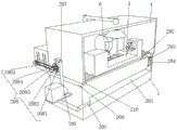
Fig. 1 is a schematic view of the appearance structure of the present invention;
FIG. 2 is a schematic view of the cleaning mechanism of the present invention;
FIG. 3 is a schematic structural view of the collecting mechanism of the present invention;
FIG. 4 is a schematic view of the protection mechanism of the present invention;
fig. 5 is an enlarged view of a in fig. 4.
In the figure: 1. a bed body; 2. a cleaning mechanism; 201. a water storage tank; 202. a water discharge tank; 203. a filter screen; 204. activated carbon; 205. a first water delivery pipe; 206. a water pump; 207. a second water delivery pipe; 208. a drive assembly; 2081. a housing; 2082. a guide vane; 2083. a first rotating lever; 2084. a first drive pulley; 2085. a belt; 209. a third water delivery pipe; 210. a spray head; 3. a collection mechanism; 301. a collection box; 302. a conduit; 303. an air suction hood; 304. a dust screen; 305. a fan; 306. a second rotating lever; 307. a second transmission wheel; 4. a protection mechanism; 401. a protective cover; 402. a slide plate; 403. a handle; 404. a chute; 405. a fixed block; 406. a spring; 407. buckling; 408. a card slot; 5. a clamp; 6. and grinding the grinding wheel.
Detailed Description
The technical solutions in the embodiments of the present invention will be described clearly and completely with reference to the accompanying drawings in the embodiments of the present invention, and it is obvious that the described embodiments are only some embodiments of the present invention, not all embodiments. Based on the embodiments in the present invention, all other embodiments obtained by a person skilled in the art without creative efforts all belong to the protection scope of the present invention.
In the specific implementation: as shown in fig. 1-5, a grinding machine for machining, comprising a machine body 1, a clamp 5 arranged on the top end of the machine body 1, and a grinding wheel 6 arranged on one side of the top end of the machine body 1; the cleaning mechanism 2 is arranged on one side of the lathe bed 1, and the cleaning mechanism 2 is used for washing the scraps on the surface of the workbench; the collecting mechanism 3 is arranged on the back surface of the lathe bed 1 and is used for carrying out centralized treatment on the scraps generated during workpiece grinding; the protection mechanism 4 is arranged at the top end of the lathe bed 1 and used for preventing chips from splashing everywhere during workpiece grinding; wherein, clearance mechanism 2 is including setting up in the catch basin 201 of 1 inner wall of lathe bed, 1 top of lathe bed is provided with two water drainage tank 202 respectively, water drainage tank 202 bottom is linked together with catch basin 201, catch basin 201 opposite side intercommunication has first raceway 205, the first raceway 205 other end intercommunication has water pump 206, water pump 206 top one end intercommunication has second raceway 207, the second raceway 207 other end intercommunication has drive assembly 208, drive assembly 208 bottom intercommunication has third raceway 209, third raceway 209 one side intercommunication has a plurality of shower nozzles 210.
As shown in fig. 2, the driving assembly 208 includes a housing 2081 communicated with the other end of the second water pipe 207, the inner wall of the housing 2081 is rotatably connected with a guide vane 2082 which is uniformly distributed, a first rotating rod 2083 is fixedly connected with the axis at one side of the guide vane 2082, a first driving wheel 2084 is fixedly connected with the surface of the first rotating rod 2083, a belt 2085 is connected with the surface of the first driving wheel 2084 in a transmission manner, a filter screen 203 is arranged on the inner wall of the water discharge groove 202, activated carbon 204 is arranged at the bottom end of the inner wall of the water discharge groove 202, a water pump 206 is started to suck water out from the water storage groove 201 through the first water pipe 205, then the water is conveyed into the housing 2081 through the water pump 206, the impact force generated by dropping of the water flow drives the rotation of the 2082, the guide vane 2082 drives the first driving wheel 2084 to rotate through the first rotating rod 2083, while the guide vane 2082 rotates, the water flow is conveyed into the spray head 210 through the third water pipe, the spray head 210 sprays the water on the water discharge groove 202, debris is treated at the inclined position of the guide vane 203, the inclined position, the debris filtered by the filter screen 203, the debris filtered by the filter table, the water filter table 209, the waste is reduced, and the waste of the water is reduced, and the waste generated by the water treatment table 201.
As shown in fig. 3, the collecting mechanism 3 includes a collecting box 301 disposed at the back of the protection mechanism 4, the inner wall of the collecting box 301 is provided with a dust screen 304, one side of the inner wall of the collecting box 301 is provided with a fan 305, one side of the fan 305 is fixedly connected with a second rotating rod 306, one end of the second rotating rod 306 runs through the collecting box 301, the surface of the second rotating rod 306 is fixedly connected with a second driving wheel 307, the second driving wheel 307 is in transmission connection with a belt 2085, the top end of the collecting box 301 is communicated with a guide pipe 302, the other end of the guide pipe 302 is fixedly connected with an air suction cover 303, the first rotating rod 2083 drives the second rotating rod 306 to rotate through the belt 2085, the second rotating rod 306 runs through the collecting box 301 to drive the fan 305 to rotate, the fan 305 sucks the fragments generated by the workpiece during grinding through the guide pipe 302 and the air suction cover 303 into the collecting box 301, the air suction cover 303 is disposed at the top end of the grinding wheel 6, the fragments can be effectively reduced, and the fragments can be splashed everywhere, and the fragments can be intensively processed.
As shown in fig. 4 and 5, the protection mechanism 4 includes a protection cover 401 fixedly connected to the top end of the bed 1, a sliding groove 404 is formed in the inner wall of the protection cover 401, a sliding plate 402 matched with the sliding groove 404 is slidably connected to the surface of the protection cover 401, a handle 403 is fixedly connected to the surface of the sliding plate 402, fixing blocks 405 are fixedly connected to two sides of the protection cover 401, a buckle 407 is slidably connected to the inner wall of the fixing block 405, a spring 406 is arranged on one side of the buckle 407, a clamping groove 408 matched with the buckle 407 is formed in the inner wall of the protection cover 401, the sliding plate 402 is moved upwards through the handle 403 by the sliding plate 402, after the sliding plate is moved to a certain height, the buckle 407 arranged in the fixing blocks 405 on two sides of the protection cover 401 is popped out of the sliding groove 408 through the spring 406, the sliding plate 402 is limited, chips generated during grinding of the workpiece can be prevented from splashing out of the workbench, and pollution of the chips to the working environment is reduced.
When the utility model is used, the sliding plate 402 moves upwards through the sliding groove 404 by pulling the handle 403, after the sliding plate is moved to a certain height, the buckle 407 arranged in the fixing block 405 at the two sides of the protective cover 401 is popped out from the clamping groove 408 into the sliding groove 404 through the spring 406, the sliding plate 402 is limited, the workpiece is clamped, the pulling buckle 407 returns to the original position, the sliding plate 402 slides downwards, the protective cover 401 is closed, when the workpiece is ground, the water pump 206 is started to suck out the water in the water storage tank 201 through the first water pipe 205, then the water is conveyed into the shell 2081 through the second water pipe 207 through the water pump 206, the guide vane 2082 is driven to rotate by the falling impact force of the water flow, the guide vane 2082 drives the first driving wheel 2084 to rotate through the first rotating rod 2083, the first driving wheel 2084 drives the belt 2085 to rotate, when the guide vane 2082 rotates, water flow is conveyed into the spray head 210 through the third water conveying pipe 209, the spray head 210 sprays water on the drainage groove 202, the water flow brings debris to the filter screen 203 along the inclined position of the drainage groove 202 for filtering, the water flow is filtered through the activated carbon 204, the filtered water is conveyed into the water storage groove 201 to form water circulation, when the first rotating rod 2083 is used, the first rotating rod 2083 drives the second rotating rod 306 to rotate through the belt 2085, the second rotating rod 306 penetrates through the collection box 301 to drive the fan 305 to rotate, the fan 305 sucks the debris generated during workpiece grinding into the collection box 301 through the guide pipe 302 and the air suction cover 303, after the workpiece is ground, the sliding plate 402 moves upwards through the handle 403, the buckle 407 limits the sliding plate 402, and the protective cover 401 is opened to take out the workpiece.
Furthermore, it should be understood that although the present description refers to embodiments, not every embodiment may contain only a single embodiment, and such description is for clarity only, and those skilled in the art should integrate the description, and the embodiments may be combined as appropriate to form other embodiments understood by those skilled in the art.
Claims (6)
1. A grinding machine for machining, characterized by comprising:
the grinding machine comprises a machine body (1), wherein a clamp (5) is arranged at the top end of the machine body (1), and a grinding wheel (6) is arranged on one side of the top end of the machine body (1);
the cleaning mechanism (2) is used for washing the scraps on the surface of the workbench, and the cleaning mechanism (2) is arranged on one side of the lathe bed (1);
the collecting mechanism (3) is used for carrying out centralized treatment on the scraps generated during workpiece grinding and is arranged on the back surface of the lathe bed (1);
the protection mechanism (4) is arranged at the top end of the lathe bed (1), and is used for preventing chips from splashing everywhere during workpiece grinding;
the cleaning mechanism (2) comprises a water storage tank (201) arranged on the inner wall of the bed body (1), two water drainage tanks (202) are arranged at the top end of the bed body (1) respectively, the bottom ends of the water drainage tanks (202) are communicated with the water storage tank (201), a first water pipe (205) is communicated with the other side of the water storage tank (201), a water pump (206) is communicated with the other end of the first water pipe (205), a second water pipe (207) is communicated with one end of the top end of the water pump (206), a driving assembly (208) is communicated with the other end of the second water pipe (207), a third water pipe (209) is communicated with the bottom end of the driving assembly (208), and a plurality of spray heads (210) are communicated with one side of the third water pipe (209).
2. The grinding machine for machining according to claim 1, characterized in that: drive assembly (208) are including communicateing casing (2081) in second raceway (207) other end, casing (2081) inner wall rotates and is connected with evenly distributed's stator (2082), stator (2082) one side axle center department fixedly connected with first rotation pole (2083), first rotation pole (2083) fixed surface is connected with first drive wheel (2084), first drive wheel (2084) surface transmission is connected with belt (2085).
3. The grinding machine for machining according to claim 2, characterized in that: the water draining device is characterized in that a filter screen (203) is arranged on the inner wall of the water draining groove (202), and activated carbon (204) is arranged at the bottom end of the inner wall of the water draining groove (202).
4. The grinding machine for machining according to claim 1, characterized in that: collect mechanism (3) including setting up in collecting box (301) at the protection machanism (4) back, collecting box (301) inner wall is provided with dust screen (304), collecting box (301) inner wall one side is provided with fan (305), fan (305) one side fixedly connected with second dwang (306), collecting box (301) is run through to second dwang (306) one end, second dwang (306) fixed surface is connected with second drive wheel (307), second drive wheel (307) are connected with belt (2085) transmission, collecting box (301) top intercommunication has pipe (302), pipe (302) other end fixedly connected with suction hood (303).
5. The grinding machine for machining according to claim 1, characterized in that: protection machanism (4) are including protection casing (401) of fixed connection in lathe bed (1) top, protection casing (401) inner wall is provided with spout (404), protection casing (401) surface sliding connection have with spout (404) assorted slide (402), slide (402) surface fixed connection has handle (403).
6. The grinding machine for machining according to claim 5, characterized in that: the protection casing (401) both sides equal fixedly connected with fixed block (405), fixed block (405) inner wall sliding connection has buckle (407), buckle (407) one side is provided with spring (406), protection casing (401) inner wall be provided with buckle (407) assorted draw-in groove (408).
Priority Applications (1)
| Application Number | Priority Date | Filing Date | Title |
|---|---|---|---|
| CN202222905287.5U CN218461819U (en) | 2022-11-02 | 2022-11-02 | Grinding machine for machining |
Applications Claiming Priority (1)
| Application Number | Priority Date | Filing Date | Title |
|---|---|---|---|
| CN202222905287.5U CN218461819U (en) | 2022-11-02 | 2022-11-02 | Grinding machine for machining |
Publications (1)
| Publication Number | Publication Date |
|---|---|
| CN218461819U true CN218461819U (en) | 2023-02-10 |
Family
ID=85149892
Family Applications (1)
| Application Number | Title | Priority Date | Filing Date |
|---|---|---|---|
| CN202222905287.5U Active CN218461819U (en) | 2022-11-02 | 2022-11-02 | Grinding machine for machining |
Country Status (1)
| Country | Link |
|---|---|
| CN (1) | CN218461819U (en) |
-
2022
- 2022-11-02 CN CN202222905287.5U patent/CN218461819U/en active Active
Similar Documents
| Publication | Publication Date | Title |
|---|---|---|
| CN114851018A (en) | Special ceramic polishing system | |
| CN213054145U (en) | Grinding machine convenient to clearance piece | |
| CN218461819U (en) | Grinding machine for machining | |
| CN213532061U (en) | Retrieve clastic metal workpiece grinding device | |
| CN211681179U (en) | Vertical elevating platform milling machine | |
| CN218137328U (en) | Cooling liquid recycling device of plane milling and grinding machine | |
| CN212444605U (en) | Grinding and polishing device capable of collecting waste materials | |
| CN216608227U (en) | Cutting off machine convenient to quick chip removal | |
| CN213439119U (en) | Dust-proof device of surface grinding machine | |
| CN113305657B (en) | Cylindrical grinding machine | |
| CN214817525U (en) | Environment-friendly grinding machine for machining | |
| CN214445584U (en) | Circulating coolant flushing assembly for grinding machine | |
| CN212020452U (en) | Intelligent grinding machine cutting protection device based on Internet of things | |
| CN210633431U (en) | Polishing device | |
| CN216608291U (en) | Grinding wheel assembling structure of cylindrical grinding machine | |
| CN213647079U (en) | Burnishing machine convenient to remove bits | |
| CN217167961U (en) | Cleaning mechanism of polishing machine | |
| CN218518431U (en) | Grinding machine for machining iron fan blades | |
| CN215357962U (en) | Waste cleaning device for grinding machine | |
| CN214923239U (en) | Dust protected abrasive machine | |
| CN220533841U (en) | Grinding machine with dust recycling function | |
| CN217860756U (en) | Anti-blocking structure of numerically controlled grinder | |
| CN218891666U (en) | Non-ferrous metal inner and outer surface polishing machine | |
| CN217859164U (en) | Machine tool for machining steel plug thread of air condition compressor | |
| CN217394497U (en) | Automatic grinding device for tool of lock |
Legal Events
| Date | Code | Title | Description |
|---|---|---|---|
| GR01 | Patent grant | ||
| GR01 | Patent grant |