CN218370443U - Full-automatic polishing and feeding device for table tennis bat - Google Patents
Full-automatic polishing and feeding device for table tennis bat Download PDFInfo
- Publication number
- CN218370443U CN218370443U CN202222094616.2U CN202222094616U CN218370443U CN 218370443 U CN218370443 U CN 218370443U CN 202222094616 U CN202222094616 U CN 202222094616U CN 218370443 U CN218370443 U CN 218370443U
- Authority
- CN
- China
- Prior art keywords
- feeding
- polishing
- lifting
- guide rail
- sucker
- Prior art date
- Legal status (The legal status is an assumption and is not a legal conclusion. Google has not performed a legal analysis and makes no representation as to the accuracy of the status listed.)
- Active
Links
Images


Abstract
The utility model relates to the field of machinary, concretely relates to full-automatic material feeding unit that polishes of table tennis bat. A full-automatic table tennis bat polishing and feeding device comprises a polishing and feeding device body, wherein the polishing and feeding device body comprises a feeding lifting device, a conveying device and a polishing host machine, and the feeding lifting device, the conveying device and the polishing host machine are sequentially arranged from right to left; the feeding lifting device comprises a feeding lifter, a lifting platform used for placing the racket is arranged on the feeding lifter, and a first manipulator used for grabbing the racket is arranged on one side of the lifting platform. The utility model discloses a this design provides a full-automatic material feeding unit that polishes of table tennis bat, has realized full-automatic unmanned operation, has avoided the workman to be liable to the situation emergence of dust occupational disease in dust environment work to improve the quality of polishing and production efficiency of product, alleviateed the recruitment cost.
Description
Technical Field
The utility model relates to the field of machinary, specifically, relate to a full-automatic material feeding unit that polishes of table tennis bat.
Background
The table tennis is a popular ball sports item, a table tennis player strikes the table tennis with the help of the table tennis to realize attack, confrontation and defense in table tennis sports, however, the table tennis bat needs to be polished in the production process, the table tennis bat is basically polished manually or semi-automatically in the current industry, and the problems of uneven polishing, irregularity, appearance deformation, poor quality, labor waste, high cost and the like exist, and due to long-term manual polishing of workers, the working environment of the workers is poor, and a large amount of dust is easily absorbed, so that dust occupational diseases are caused.
An effective solution to the problems in the related art has not been proposed yet.
SUMMERY OF THE UTILITY MODEL
The utility model aims at providing a table tennis bat full-automatic material feeding unit that polishes to solve above-mentioned at least one technical problem.
In order to achieve the above purpose, the utility model adopts the following technical scheme:
a full-automatic polishing and feeding device for table tennis bats comprises a polishing and feeding device body, and is characterized in that the polishing and feeding device body comprises a feeding lifting device, a conveying device and a polishing main machine, wherein the feeding lifting device, the conveying device and the polishing main machine are sequentially arranged from right to left;
the feeding lifting device comprises a feeding lifter, a lifting platform for placing the racket is arranged on the feeding lifter, and a first manipulator for grabbing the racket is arranged on one side of the lifting platform;
the conveying device comprises a conveying frame, a conveying belt is arranged on the conveying frame, and the conveying belt is arranged below the first manipulator;
the polishing main machine comprises a sucker feeding device, a work sliding table, a polishing mechanism and a machine shell, wherein the sucker feeding device comprises a sucker feeding frame and a positioning mechanism, a second mechanical arm for grabbing a racket is arranged on the sucker feeding frame, the second mechanical arm is arranged above the conveying belt, the positioning mechanism is arranged on one side of the sucker feeding frame, and the work sliding table is arranged on one side of the positioning mechanism;
the grinding mechanism comprises an abrasive belt grinding machine, and the abrasive belt grinding machine is arranged in the shell and located on one side of the working sliding table.
The feeding lifter is arranged on the frame base, a first horizontal guide rail transversely arranged is arranged on the frame base, a feeding sliding plate is arranged on the first horizontal guide rail, a first feeding cylinder used for pushing the feeding sliding plate is arranged on one side of the first horizontal guide rail, and a first mechanical arm is arranged on the feeding sliding plate and located above the lifting platform.
First manipulator includes vacuum chuck, is used for the drive vacuum chuck's sucking disc servo motor, be equipped with the servo motor installing support on the material loading slide, sucking disc servo motor sets up on the servo motor installing support, vacuum chuck is located the below of servo motor installing support.
The conveying frame is provided with a speed reducing motor, a rotating shaft of the speed reducing motor is connected with a driving belt wheel, the conveying belt is sleeved on the driving belt wheel and a driven belt wheel, guide strips are arranged on two sides of the conveying belt, and first positioning cylinders are arranged on the guide strips.
The sucking disc feeding frame is fixed on the machine shell, a second horizontal guide rail which is transversely arranged and is positioned above the conveying belt is arranged on the sucking disc feeding frame, a sucking disc sliding seat is arranged on the second horizontal guide rail, and a second feeding air cylinder for pushing the sucking disc sliding seat is arranged on one side of the second horizontal guide rail;
the second manipulator comprises a sucker and a sucker lifting cylinder for driving the sucker, the sucker lifting cylinder is arranged on the sucker sliding seat, and the sucker is fixed to the lower portion of the sucker lifting cylinder.
The first horizontal guide rail and the second horizontal guide rail are respectively arranged on two sides of the conveying belt.
The positioning mechanism comprises a positioning seat bottom plate arranged on one side of the sucker feeding frame, a positioning seat lifting plate is arranged above the positioning seat bottom plate, a positioning seat lifting cylinder is arranged on the positioning seat lifting plate, and a second positioning cylinder used for clamping a racket is arranged on the positioning seat lifting plate.
The number of the second positioning cylinders is two, and the two second positioning cylinders are arranged on two side portions of the positioning seat lifting plate respectively.
The work slip table is including setting up positioning mechanism one side just is the slip table guide rail of vertical setting, ann has the slip table on the slip table guide rail, be equipped with roating seat and the liftout slide that is relative setting on the slip table, roating seat one side is equipped with rotation axis servo motor, initiative liftout pivot is connected in rotation axis servo motor's pivot, ann has the liftout cylinder on the liftout slide, the front portion of liftout cylinder be equipped with initiative liftout pivot assorted driven liftout pivot.
The grinding mechanism comprises a grinding machine guide rail which is arranged on one side of the working sliding table and is transversely arranged, a sliding mounting plate is arranged on the grinding machine guide rail, a fixed support is arranged on the sliding mounting plate, the fixed support is connected with a movable support through a rotating shaft, and the abrasive belt grinding machine is fixed on the movable support;
the fixed support is provided with a swing angle cylinder, one side part of the swing angle cylinder is connected with the fixed support, and the other side part of the swing angle cylinder is connected with the movable support through a rotating shaft.
The utility model discloses a this design provides a full-automatic material feeding unit that polishes of table tennis bat, has realized full-automatic unmanned operation, has avoided the workman to take place at the situation that dusty environment work is liable to dust occupational disease to improve the quality and the production efficiency of polishing of product, alleviateed the recruitment cost.
Drawings
FIG. 1 is a schematic view of a part of the structure of the present invention;
fig. 2 is an exploded view of a part of the structure of the feeding and lifting device of the present invention;
fig. 3 is a partially exploded view of the conveying device of the present invention;
fig. 4 is an exploded view of a part of the structure of the sucker loading device of the present invention;
FIG. 5 is an exploded view of a portion of the structure of the work slide of the present invention;
fig. 6 is a schematic exploded view of a part of the structure of the polishing mechanism of the present invention.
Detailed Description
The following description will further describe embodiments of the present invention with reference to the accompanying drawings.
As shown in fig. 1 to 6, a full-automatic polishing and feeding device for table tennis rackets comprises a polishing and feeding device body, wherein the polishing and feeding device body comprises a feeding lifting device 3, a conveying device 2 and a polishing main machine 1, and the feeding lifting device 3, the conveying device 2 and the polishing main machine 1 are sequentially arranged from right to left; the feeding lifting device 3 comprises a feeding lifting machine, a lifting platform 11 for placing the racket 10 is arranged on the feeding lifting machine, and a first manipulator 9 for grabbing the racket 10 is arranged on one side of the lifting platform 11; the conveying device 2 comprises a conveying frame, a conveying belt is arranged on the conveying frame, and the conveying belt is arranged below the first manipulator 9; the polishing main machine 1 comprises a sucker feeding device 8, a work sliding table 4, a polishing mechanism 6 and a machine shell, wherein the sucker feeding device 8 comprises a sucker feeding frame and a positioning mechanism, a second mechanical arm for grabbing a racket 10 is arranged on the sucker feeding frame, the second mechanical arm is arranged above a conveying belt, the positioning mechanism 7 is arranged on one side of the sucker feeding frame, and the work sliding table 4 is arranged on one side of the positioning mechanism 7; the grinding mechanism 6 comprises a belt sander arranged in the housing and located on one side of the work slide 4. The utility model discloses a this design provides a full-automatic material feeding unit that polishes of table tennis bat, has realized full-automatic unmanned operation, has avoided the workman to be liable to the situation emergence of dust occupational disease in dust environment work to improve the quality of polishing and production efficiency of product, alleviateed the recruitment cost.
When the design is used, the rackets 10 are staggered, stacked and placed, so that the handles of the rackets 10 are placed on the lifting platform 11 of the feeding lifting device 3 in a cross direction to place enough rackets 10; the racket 10 is grabbed to the conveying belt of the conveying device 2 through the first mechanical arm 9, the conveying belt sends the racket 10 to the conveying device 2, the conveying device is close to one side of the grinding host 1 and is located below the second mechanical arm, the second mechanical arm grabs the positioning mechanism 7 through the racket 10, the racket 10 on the positioning mechanism 7 is moved to the grinding mechanism 6 located in the shell through the work sliding table 4, the racket 10 is close to an abrasive belt of the abrasive belt grinding machine, the grinding process of the table tennis racket is completed through the abrasive belt grinding machine, the whole grinding process can work circularly, and unmanned grinding operation of the table tennis racket is achieved.
The material loading lift sets up on frame base 31, is equipped with the first horizontal guide rail 32 that is horizontal setting on the frame base 31, is equipped with material loading slide 33 on the first horizontal guide rail 32, and first horizontal guide rail 32 one side is equipped with the first material loading cylinder 34 that is used for promoting material loading slide 33, and ann has first manipulator 9 on the material loading slide 33, and first manipulator 9 is located lift platform 11's top. The first mechanical arm 9 comprises a vacuum sucker 35 and a sucker servo motor 36 for driving the vacuum sucker 35, a servo motor mounting support 37 is arranged on the feeding sliding plate, the sucker servo motor is arranged on the servo motor mounting support 37, and the vacuum sucker 35 is located below the servo motor mounting support 37. After the table tennis bat handle is assembled, the whole thickness is inconsistent, so that the difficulty is brought to automatic feeding, the feeding lifting device 3 can drive the feeding sliding plate 33 to transversely move on the first horizontal guide rail 32 through the first feeding cylinder 34, so that the vacuum suction cup 35 below the suction cup servo motor 36 can move to the upper part of the bat 10 and grab the bat 10, and the feeding process of the bat 10 is realized.
The conveying frame 21 is provided with a speed reducing motor 22, a rotating shaft of the speed reducing motor 22 is connected with a driving belt wheel 23, a conveying belt 24 is sleeved on the driving belt wheel 23 and a driven belt wheel 25, guide strips 26 are arranged on two sides of the conveying belt 24, and a first positioning cylinder 27 is arranged on the guide strips 26. During the moving of the racket 10 by the conveyer belt 21, the position of the racket 10 can be adjusted by the cooperation of the guide strip 26 and the first positioning cylinder 27.
The sucking disc feeding frame 81 is fixed on the machine shell, a second horizontal guide rail 82 which is transversely arranged and is positioned above the conveying belt is arranged on the sucking disc feeding frame 81, a sucking disc sliding seat 83 is arranged on the second horizontal guide rail 82, and a second feeding air cylinder 84 for pushing the sucking disc sliding seat 83 is arranged on one side of the second horizontal guide rail 82; the second manipulator comprises a suction cup 86 and a suction cup lifting cylinder 85 for driving the suction cup 86, the suction cup lifting cylinder 85 is arranged on the suction cup sliding base 83, and the suction cup 86 is fixed at the lower part of the suction cup lifting cylinder 85. The suction cup feeding device 8 can drive the suction cup sliding seat 83 to move transversely on the second horizontal guide rail 82 through the second feeding air cylinder 84, so that the suction cup 86 below the suction cup lifting air cylinder 85 moves to the upper part of the racket 10 and grabs the racket 10. In order to reduce the occupied space of the equipment, the first horizontal guide rail and the second horizontal guide rail 82 are respectively arranged at two sides of the conveying belt.
The positioning mechanism 7 comprises a positioning seat bottom plate 71 arranged on one side of the sucking disc feeding frame, a positioning seat lifting plate 72 is arranged above the positioning seat bottom plate 71, a positioning seat lifting cylinder 73 is arranged on the positioning seat lifting plate 72, and a second positioning cylinder 74 used for clamping the racket 10 is arranged on the positioning seat lifting plate 72. After the racket 10 is delivered to the positioning mechanism 7, the racket 10 is clamped by the second positioning cylinder 74, and the correct position is located, and then the positioning seat lifting cylinder 73 raises or lowers the positioning seat lifting plate 72 to adjust the height of the racket 10, so that the racket 10 can be moved by the work slide 4. In order to adapt to rackets 10 with different swing directions, two second positioning cylinders 74 are provided, and the two second positioning cylinders 74 are respectively disposed on both side portions of the positioning socket lifting plate 72.
Work slip table 4 is including setting up the slip table guide rail 41 that just is vertical setting in positioning mechanism 7 one side, ann has slip table 42 on the slip table guide rail 41, be equipped with roating seat 5 and liftout slide 45 that are relative setting on the slip table 42, 5 one side of roating seat is equipped with rotation axis servo motor 43, initiative liftout pivot 44 is connected in rotation axis servo motor 43's pivot, ann has liftout cylinder 46 on the liftout slide 45, the front portion of liftout cylinder 46 be equipped with initiative liftout pivot 44 assorted driven liftout pivot 47. The work sliding table 4 comprises a first ball screw 48 and a first servo motor 49 used for driving the first ball screw 48, the first ball screw 48 comprises a first screw rod which is longitudinally arranged and is parallel to the sliding table guide rail 41 and a first nut which is arranged on the first screw rod, the first screw rod is connected with a rotating shaft of the first servo motor 49, and the first nut is connected with the sliding table 42. The work sliding table 4 moves to the position of the positioning mechanism 7 under the power of the first servo motor 49, clamps the racket 10 through the driving ejecting rotating shaft 44 on the rotating base 5 arranged at the front end of the work sliding table 4 and the driven ejecting rotating shaft 47 on the ejecting sliding base 45, and sends the racket 10 to the side of the grinding mechanism 6 to be close to the abrasive belt of the abrasive belt grinding machine.
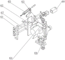
The grinding mechanism 6 comprises a grinding machine guide rail 61 which is arranged on one side of the working sliding table 4 and transversely arranged, a sliding mounting plate 62 is arranged on the grinding machine guide rail 61, a fixed support 63 is arranged on the sliding mounting plate 62, the fixed support 63 is connected with a movable support 64 through a rotating shaft, and an abrasive belt grinding machine 69 is fixed on the movable support 64; the fixed support 63 is provided with a swing angle cylinder 65, one side part of the swing angle cylinder 65 is connected with the fixed support 63, and the other side part of the swing angle cylinder 65 is connected with the movable support 64 through a rotating shaft. Grinding machanism 6 includes second ball 67, is used for driving second ball 67's second servo motor 68, and second ball 67 is including being horizontal setting and being on a parallel with the second screw rod of polisher guide rail, the second nut of setting on the second screw rod, and the second screw rod links to each other with second servo motor 68's pivot, and the second nut links to each other with sliding mounting board 62. The polishing mechanism 6 drives the sliding mounting plate 62 through the second ball screw 67 under the power of the second servo motor 68, and polishes according to the movement of the racket 10, and when the fixed bracket 63 mounted on the sliding mounting plate 62 moves to the root position of the handle of the table tennis racket under the driving of the second servo motor 68, the movable bracket 64 rotates under the action of the swing angle cylinder 65, so as to drive the abrasive belt polishing machine 69 to deflect and change the angle of the abrasive belt, thereby achieving better polishing effect. Under first servo motor, second servo motor and rotation axis servo motor's cooperation work, triaxial servo can accomplish the process of polishing to the table tennis bat according to the dimensional requirement, improves the effect of polishing to the table tennis bat, has realized the unmanned operation of polishing of table tennis bat.
Finally, it should be noted that: although the present invention has been described in detail with reference to the foregoing embodiments, it will be apparent to those skilled in the art that modifications may be made to the embodiments described in the foregoing embodiments, or equivalents may be substituted for elements thereof. Any modification, equivalent replacement, or improvement made within the spirit and principle of the present invention should be included in the protection scope of the present invention.
Claims (10)
1. A full-automatic grinding and feeding device for table tennis bats comprises a grinding and feeding device body and is characterized in that the grinding and feeding device body comprises a feeding lifting device, a conveying device and a grinding host machine, wherein the feeding lifting device, the conveying device and the grinding host machine are sequentially arranged from right to left;
the feeding lifting device comprises a feeding lifting machine, a lifting platform for placing a racket is arranged on the feeding lifting machine, and a first mechanical arm for grabbing the racket is arranged on one side of the lifting platform;
the conveying device comprises a conveying frame, a conveying belt is arranged on the conveying frame, and the conveying belt is arranged below the first manipulator;
the polishing main machine comprises a sucker feeding device, a work sliding table, a polishing mechanism and a machine shell, wherein the sucker feeding device comprises a sucker feeding frame and a positioning mechanism, a second mechanical arm for grabbing a racket is arranged on the sucker feeding frame, the second mechanical arm is arranged above the conveying belt, the positioning mechanism is arranged on one side of the sucker feeding frame, and the work sliding table is arranged on one side of the positioning mechanism;
the grinding mechanism comprises an abrasive belt grinding machine, and the abrasive belt grinding machine is arranged in the shell and located on one side of the working sliding table.
2. The full-automatic grinding and feeding device for table tennis rackets as claimed in claim 1, wherein the feeding lifter is arranged on a frame base, the frame base is provided with a first horizontal guide rail arranged transversely, the first horizontal guide rail is provided with a feeding sliding plate, one side of the first horizontal guide rail is provided with a first feeding cylinder for pushing the feeding sliding plate, the feeding sliding plate is provided with the first manipulator, and the first manipulator is positioned above the lifting platform.
3. The full-automatic table tennis bat polishing and feeding device according to claim 2, wherein the first manipulator comprises a vacuum chuck and a chuck servo motor for driving the vacuum chuck, the feeding slide plate is provided with a servo motor mounting bracket, the chuck servo motor is arranged on the servo motor mounting bracket, and the vacuum chuck is located below the servo motor mounting bracket.
4. The full-automatic grinding and feeding device for table tennis rackets as claimed in claim 1, wherein the carriage is provided with a reduction motor, a rotating shaft of the reduction motor is connected with a driving pulley, the conveying belt is sleeved on the driving pulley and a driven pulley, two sides of the conveying belt are provided with guide strips, and the guide strips are provided with first positioning cylinders.
5. The full-automatic grinding and feeding device for table tennis rackets as claimed in claim 1 or 2, wherein the suction cup loading frame is fixed on the machine shell, a second horizontal guide rail which is transversely arranged and is positioned above the conveying belt is arranged on the suction cup loading frame, a suction cup sliding seat is arranged on the second horizontal guide rail, and a second feeding cylinder for pushing the suction cup sliding seat is arranged on one side of the second horizontal guide rail;
the second manipulator comprises a sucker and a sucker lifting cylinder used for driving the sucker, the sucker lifting cylinder is arranged on the sucker sliding seat, and the sucker is fixed to the lower portion of the sucker lifting cylinder.
6. The full-automatic grinding and feeding device for table tennis rackets as claimed in claim 5, wherein the first horizontal guide rail and the second horizontal guide rail are respectively disposed at both sides of the conveyor belt.
7. The fully automatic table tennis bat sanding feeding device of claim 1, wherein the positioning mechanism comprises a positioning seat bottom plate disposed at one side of the suction cup loading frame, a positioning seat lifting plate is disposed above the positioning seat bottom plate, a positioning seat lifting cylinder is disposed on the positioning seat lifting plate, and a second positioning cylinder for holding the table tennis bat is disposed on the positioning seat lifting plate.
8. The full-automatic grinding and feeding device for table tennis rackets as claimed in claim 7, wherein the number of the second positioning cylinders is two, and the two second positioning cylinders are respectively disposed on two side portions of the positioning seat lifting plate.
9. The full-automatic grinding and feeding device for table tennis rackets as claimed in claim 1, wherein the work sliding table comprises a sliding table guide rail which is arranged on one side of the positioning mechanism and is arranged longitudinally, a sliding table is arranged on the sliding table guide rail, a rotating seat and a material ejecting sliding seat which are arranged oppositely are arranged on the sliding table, a rotating shaft servo motor is arranged on one side of the rotating seat, a rotating shaft of the rotating shaft servo motor is connected with a driving material ejecting rotating shaft, a material ejecting cylinder is arranged on the material ejecting sliding seat, and a driven material ejecting rotating shaft matched with the driving material ejecting rotating shaft is arranged at the front part of the material ejecting cylinder.
10. The full-automatic table tennis bat polishing and feeding device according to claim 1 or 9, wherein the polishing mechanism comprises a polishing machine guide rail transversely arranged on one side of the work sliding table, a sliding mounting plate is arranged on the polishing machine guide rail, a fixed bracket is arranged on the sliding mounting plate, the fixed bracket is connected with a movable bracket through a rotating shaft, and the belt polishing machine is fixed on the movable bracket;
the fixed support is provided with a swing angle cylinder, one side part of the swing angle cylinder is connected with the fixed support, and the other side part of the swing angle cylinder is connected with the movable support through a rotating shaft.
Priority Applications (1)
| Application Number | Priority Date | Filing Date | Title |
|---|---|---|---|
| CN202222094616.2U CN218370443U (en) | 2022-08-09 | 2022-08-09 | Full-automatic polishing and feeding device for table tennis bat |
Applications Claiming Priority (1)
| Application Number | Priority Date | Filing Date | Title |
|---|---|---|---|
| CN202222094616.2U CN218370443U (en) | 2022-08-09 | 2022-08-09 | Full-automatic polishing and feeding device for table tennis bat |
Publications (1)
| Publication Number | Publication Date |
|---|---|
| CN218370443U true CN218370443U (en) | 2023-01-24 |
Family
ID=84965683
Family Applications (1)
| Application Number | Title | Priority Date | Filing Date |
|---|---|---|---|
| CN202222094616.2U Active CN218370443U (en) | 2022-08-09 | 2022-08-09 | Full-automatic polishing and feeding device for table tennis bat |
Country Status (1)
| Country | Link |
|---|---|
| CN (1) | CN218370443U (en) |
-
2022
- 2022-08-09 CN CN202222094616.2U patent/CN218370443U/en active Active
Similar Documents
| Publication | Publication Date | Title |
|---|---|---|
| CN110680049B (en) | Complete equipment for polishing shoe sole | |
| CN107199485B (en) | Grinding machine | |
| CN107775337A (en) | Intelligent assembly work station | |
| CN211841390U (en) | Hammer equipment of polishing | |
| CN206029539U (en) | Bend polishing machine | |
| CN108907964B (en) | Lens edging machine | |
| CN218370443U (en) | Full-automatic polishing and feeding device for table tennis bat | |
| CN210938421U (en) | Centerless grinding machine with loading and unloading device | |
| CN210388629U (en) | Full-automatic centering edge grinding device for optical lens | |
| CN209793234U (en) | Mechanical arm for double-Z-axis machine tool and double-Z-axis machine tool applying mechanical arm | |
| CN113291798B (en) | Lens processing equipment feeding and discharging device | |
| CN207824535U (en) | A kind of dustless burnishing device of metal product | |
| CN214410898U (en) | Automatic resistance repairing device | |
| CN115258678A (en) | Automatic feeding device | |
| CN210476493U (en) | Automatic chain plate grinding machine | |
| CN111922431B (en) | Automatic change circular arc saw gear grinding machine | |
| CN115008295A (en) | Edging auxiliary device for glass processing | |
| CN209754790U (en) | Full-automatic edge grinding equipment for lenses | |
| JPS61209766A (en) | Cutting device | |
| CN210099724U (en) | Feeding device of glass edge grinding machine | |
| CN214878461U (en) | Lens processing loading attachment | |
| CN214779231U (en) | Lens processing unloader | |
| CN218696787U (en) | Automatic grinding device of table tennis bat | |
| CN219581359U (en) | Novel polishing device | |
| CN217453278U (en) | Automatic grinding device of foaming shoes embryo |
Legal Events
| Date | Code | Title | Description |
|---|---|---|---|
| GR01 | Patent grant | ||
| GR01 | Patent grant |