CN218147291U - High-temperature efficient vapor-liquid open-width washing system for tatting/knitting - Google Patents
High-temperature efficient vapor-liquid open-width washing system for tatting/knitting Download PDFInfo
- Publication number
- CN218147291U CN218147291U CN202222066720.0U CN202222066720U CN218147291U CN 218147291 U CN218147291 U CN 218147291U CN 202222066720 U CN202222066720 U CN 202222066720U CN 218147291 U CN218147291 U CN 218147291U
- Authority
- CN
- China
- Prior art keywords
- cloth
- liquid
- vapor
- rotary drum
- feeding
- Prior art date
- Legal status (The legal status is an assumption and is not a legal conclusion. Google has not performed a legal analysis and makes no representation as to the accuracy of the status listed.)
- Active
Links
Images


Abstract
The utility model relates to a high-temperature and high-efficiency steam-liquid open-width washing system for tatting/knitting, belonging to the technical field of textile fabric production; comprises a cloth feeding and liquid feeding box, a cloth feeding rotary drum washing box, a cloth feeding vapor-liquid spraying box, a vapor-liquid washing box, a vapor-liquid spraying box, a cloth discharging rotary drum washing box and a cloth discharging assembly; the above components are connected in sequence. The utility model discloses a shuttle/high-efficient vapour liquid open width water washing system of knitting high temperature has compatible multiple washing technology that is suitable for, realizes high-quality fabric effects such as compliance is good, feel, the hair is effectual, fluffy degree is high, no friction vestige, the short flow of equipment, take up an area of for a short time, low tension, the fabric is fully preshrinked naturally, the deflection is little, the fine denier of fabric is arranged naturally, washing efficiency is high, the energy consumption is low.
Description
Technical Field
The utility model relates to a shuttle knitting/high-efficient vapour liquid open width water washing system of knitting high temperature belongs to textile fabric production technical field.
Background
A combined machine for dyeing, finishing and washing textile fabrics is mainly used for washing the fabric in the process of fabric blank and before and after dyeing and printing. Used for the pretreatment process, mainly desizing, boiling off, bleaching; the method is used for the finishing processes after dyeing and printing, and mainly removes surface flooding, redundant dyes, sizing agents, decomposed products and other dirt in the processing process by washing.
At present, in the field of textile printing and dyeing equipment, washing combination machines are various in types and different in specifications. A washing combination machine with a specific process is required to be configured for specific fabrics. Aiming at the problem that acid printed fabrics are easy to stain when washed by water, at present, most domestic factories generally adopt rope-shaped washing machines; aiming at the pretreatment of the woven cotton fabric, a continuous open width boiling and bleaching combination machine is usually adopted to realize the process requirements of ore removal, desizing, scouring and rinsing of the cotton fabric; the appearance, hand feeling, style and the like of some silk fabrics, knitted fabrics, some wool-like and silk-like chemical fibers and blended fabrics thereof require that dyeing and finishing processes of the silk fabrics, the knitted fabrics, the some wool-like and silk-like chemical fibers and the blended fabrics thereof are carried out in a tension-free state, and a low-tension wet finishing and washing combination machine is required. In addition, various water washing combinations are stored in the market, such as a bleaching combination machine, a mercerizing combination machine, a dyeing water washing machine, a printing water washing machine, a stacking spray water washing machine, an open-width continuous bleaching machine, an oil removal pre-shrinking water washing machine and the like; the water washers have different sizes, different energy consumption and water consumption, fixed process, poor compatibility with other processes and poor applicability to other fabrics. The washing combination machines are usually customized nonstandard according to the customer service and the fabric production condition, equipment lacks unified standards, and the production efficiency and the production quality are difficult to identify and evaluate.
Therefore, the high-temperature and high-efficiency steam-liquid open-width water washing system for tatting/knitting is provided, and has the advantages of compatibility and applicability to various water washing processes (ore removal, oil removal, desizing, scouring, bleaching, pre-shrinking, mercerizing, material soaking with liquid, and light rolling), realization of high-quality fabric effects such as good flexibility, good hand feeling, good capillary effect, high filling power, no friction trace and the like, short equipment flow, small occupied area, low tension, natural and sufficient pre-shrinking of fabric, small deformation, natural arrangement of fine denier of fabric, high water washing efficiency, low energy consumption and the like, and becomes a technical problem which is urgently needed to be solved in the technical field.
Disclosure of Invention
The utility model aims at providing a shuttle/high-efficient vapour liquid open width water washing system of knitting high temperature has compatible multiple washing technology (remove ore deposit, deoiling, destarch, boil off, bleach, preshrinking, mercerization, the material that soaks area liquid, gently roll) that is suitable for, realize that the compliance is good, feel good, the capillary is good, fluffy degree is high, high-quality fabric effects such as no friction vestige, the short flow of equipment, take up an area of for a short time, low tension, the fabric is fully preshrinked naturally, the deflection is little, fine denier of fabric natural arrangement, washing efficiency is high, the energy consumption is low.
In order to realize the purpose, the utility model adopts the following technical scheme:
a high-temperature high-efficiency vapor-liquid open-width water washing system for tatting/knitting comprises: a cloth feeding and feeding tank, a cloth feeding rotary drum washing tank, a cloth feeding vapor-liquid spraying tank, a vapor-liquid washing tank, a vapor-liquid spraying tank, a cloth discharging rotary drum washing tank and a cloth discharging assembly; the above parts are connected in sequence: the cloth feeding and feeding tank is connected with the cloth feeding rotary drum washing tank, the cloth feeding rotary drum washing tank is connected with the cloth feeding vapor-liquid spraying tank, the cloth feeding vapor-liquid spraying tank is connected with the vapor-liquid washing tank, the vapor-liquid washing tank is connected with the vapor-liquid spraying tank, the vapor-liquid spraying tank is connected with the second vapor-liquid washing tank, the second vapor-liquid washing tank is connected with the cloth discharging vapor-liquid spraying tank, the cloth discharging vapor-liquid spraying tank is connected with the cloth discharging rotary drum washing tank, and the cloth discharging rotary drum washing tank is connected with the cloth discharging assembly;
the cloth feeding vapor-liquid spraying box comprises: the device comprises a cloth feeding vapor-liquid blank cloth, a cloth feeding vapor-liquid first cloth guide roller, a cloth feeding vapor-liquid deviation correction roller, a cloth feeding vapor-liquid photoelectric tube, a cloth feeding vapor-liquid second cloth guide roller, a cloth feeding vapor-liquid first vapor-liquid spray pipe, a cloth feeding vapor-liquid air pipe, a cloth feeding vapor-liquid second vapor-liquid spray pipe and a cloth feeding vapor-liquid frame; the first cloth guide roller for feeding the cloth vapor and liquid is arranged at the upper left corner of the frame for feeding the cloth vapor and liquid, the deviation correction roller for feeding the cloth vapor and liquid is arranged at the right side of the first cloth guide roller for feeding the cloth vapor and liquid, the photoelectric tube for feeding the cloth vapor and liquid and the second cloth guide roller for feeding the cloth vapor and liquid are arranged at the middle lower part of the frame for feeding the cloth vapor and liquid, the first vapor and liquid spray pipe for feeding the cloth vapor and liquid and the second vapor and liquid spray pipe for feeding the cloth vapor and liquid are arranged at the right side of the frame for feeding the cloth vapor and liquid, and the air pipe for feeding the cloth vapor and liquid is arranged at the upper right side of the frame for feeding the cloth vapor and liquid;
the vapor-liquid washing tank and the second vapor-liquid washing tank comprise vapor-liquid washing gray cloth, a vapor-liquid washing observation window, a vapor-liquid washing tank, a vapor-liquid washing water pump, a vapor-liquid washing ball valve, a vapor-liquid washing overhaul window, a vapor-liquid washing water inlet, a vapor-liquid washing air inlet cover, a vapor-liquid washing fan and a vapor-liquid washing frame; the vapor-liquid washing inspection window is positioned in the middle of the vapor-liquid washing frame, the vapor-liquid washing tank is positioned at the upper right part of the vapor-liquid washing frame, the vapor-liquid washing water pump is positioned at the lower left part of the vapor-liquid washing frame, the vapor-liquid washing ball valve is positioned at the lower right part of the vapor-liquid washing frame, the vapor-liquid washing inspection window is positioned at the right side of the vapor-liquid washing frame, the vapor-liquid washing water inlet is positioned at one side of the vapor-liquid washing inspection window, the vapor-liquid washing air inlet cover is positioned at the inner side of the top of the vapor-liquid washing frame, and the vapor-liquid washing fan is positioned at the upper part of the vapor-liquid washing air inlet cover;
the vapour-liquid sprays the case and includes: the device comprises a vapor-liquid spraying blank cloth, a vapor-liquid spraying deviation correcting roller, a vapor-liquid spraying photoelectric tube, a vapor-liquid spraying cloth guide roller, a vapor-liquid spraying frame, a first vapor-liquid spraying pipe, a vapor-liquid spraying first air pipe, a second vapor-liquid spraying pipe, a third vapor-liquid spraying pipe, a vapor-liquid spraying second air pipe and a fourth vapor-liquid spraying pipe; the vapor-liquid spraying correction roller is installed in the middle of the vapor-liquid spraying frame, the vapor-liquid spraying photoelectric tube is located on the right side of the vapor-liquid spraying correction roller, the vapor-liquid spraying cloth guide roller is located on the right side of the vapor-liquid spraying photoelectric tube, the first vapor-liquid spraying tube and the second vapor-liquid spraying tube are symmetrically installed on the right side of the vapor-liquid spraying frame, the vapor-liquid spraying first air pipe is installed on the upper right portion of the vapor-liquid spraying frame, the third vapor-liquid spraying tube and the fourth vapor-liquid spraying tube are symmetrically installed on the left side of the vapor-liquid spraying frame, and the vapor-liquid spraying second air pipe is installed on the upper left portion of the vapor-liquid spraying frame.
Preferably, the cloth feeding liquid box comprises a blank cloth, a cloth feeding liquid water pump, an auxiliary agent box, a cloth feeding liquid first ball valve, a cloth feeding liquid second ball valve, a soaking box, a spray pipe, a cloth feeding liquid first guide roller, a cloth feeding liquid first branch roller, a cloth feeding liquid padder, an access door, a cloth feeding liquid first rubber roller, a cloth feeding liquid second guide roller, a cloth feeding liquid third guide roller, a cloth feeding liquid photoelectric tube, a cloth feeding liquid first deviation correction roller, a cloth feeding liquid second branch roller, a cloth feeding liquid third branch roller, a cloth feeding liquid fourth guide roller, a cloth feeding liquid fifth guide roller, a cloth feeding liquid sixth guide roller, a cloth feeding liquid seventh guide roller, a cloth feeding liquid limit roller, a cloth feeding liquid eighth guide roller and a cloth feeding liquid frame; the cloth feeding water pump is positioned on one side of the bottom of the cloth feeding water frame, the auxiliary agent box is positioned above the cloth feeding water pump, the cloth feeding water feeding first ball valve is positioned in the middle of the auxiliary agent box, the cloth feeding water feeding second ball valve is positioned on the right upper part of the auxiliary agent box, the soaking box is positioned above the auxiliary agent box and is connected with the auxiliary agent box through a pipeline, the spray pipe is positioned on the right side of the soaking box, the cloth feeding water feeding first rubber roller is positioned in the middle of the soaking box, the cloth feeding water feeding first cloth guiding roller and the cloth feeding water feeding second cloth guiding roller are positioned on two sides of the cloth feeding water feeding first rubber roller, the cloth feeding water feeding first branching roller is positioned on the right upper part of the cloth feeding liquid feeding first cloth guiding roller, the cloth feeding and liquid feeding padder is positioned on the right side of the cloth feeding and liquid feeding first wire dividing roller, the access door is positioned on the right upper side of the cloth feeding and liquid feeding frame, the cloth feeding and liquid feeding third cloth guide roller is positioned on the left side of the cloth feeding and liquid feeding second cloth guide roller, the cloth feeding and liquid feeding photoelectric tube is positioned above the cloth feeding and liquid feeding third cloth guide roller, the cloth feeding and liquid feeding first deviation correction roller is positioned above the left side of the cloth feeding and liquid feeding photoelectric tube, the cloth feeding and liquid feeding second wire dividing roller, the cloth feeding and liquid feeding third wire dividing roller, the cloth feeding and liquid feeding fourth cloth guide roller, the cloth feeding and liquid feeding fifth cloth guide roller, the cloth feeding and liquid feeding sixth cloth guide roller, the cloth feeding and liquid feeding seventh cloth guide roller, the cloth feeding and liquid feeding limit roller and the cloth feeding and liquid feeding eighth cloth guide roller are sequentially arranged from right to left.
Preferably, the cloth feeding rotary drum washing box comprises rotary drum grey cloth, a first cloth guide roller of the rotary drum, a second cloth guide roller of the rotary drum, a third cloth guide roller of the rotary drum, a rotary drum rubber roll, a fourth cloth guide roller of the rotary drum, a water-gas separation tank of the rotary drum, a fifth cloth guide roller of the rotary drum, a sixth cloth guide roller of the rotary drum, a seventh cloth guide roller of the rotary drum, a rotary drum water pump, a pH value sensor of the rotary drum, a rotary drum temperature sensor, a rotary drum steam pipe, a rotary drum pressure sensor, a rotary drum washing tank, a rotary drum roller, an eighth cloth guide roller of the rotary drum, a ninth cloth guide roller of the rotary drum, a tenth cloth guide roller of the rotary drum, a rotary drum dividing roller, a rotary drum padder, a rotary drum water spraying pipe, a rotary drum observation window, a rotary drum maintenance window and a rotary drum frame; the device comprises a first fabric guide roller of a rotary drum, a second fabric guide roller of the rotary drum, a third fabric guide roller of the rotary drum and a fourth fabric guide roller of the rotary drum, which are respectively arranged at the upper left corner of a rotary drum frame from top to bottom, a water-gas separation groove of the rotary drum is positioned below the third fabric guide roller of the rotary drum, a rubber roll of the rotary drum is positioned at the upper right corner of the water-gas separation groove of the rotary drum, a fifth fabric guide roller of the rotary drum, a sixth fabric guide roller of the rotary drum and a seventh fabric guide roller of the rotary drum are sequentially positioned at the lower right corner of the rubber roll to form a diagonal arrangement, a water pump of the rotary drum is arranged at the lower left corner of the rotary drum frame, a pH value sensor of the rotary drum, a temperature sensor of the rotary drum, a steam pipe of the rotary drum and a pressure sensor of the rotary drum are sequentially arranged at the bottom of the water washing groove of the rotary drum, a rotary drum is positioned at the middle of the rotary drum frame, a rotary drum roller is arranged at the middle of the water washing groove of the rotary drum, an eighth fabric guide roller, a ninth fabric guide roller, a tenth fabric guide roller of the rotary drum, a fiber dividing roller of the rotary drum is sequentially arranged at the upper part of the water washing groove of the rotary drum, and a top of the rotary drum is arranged at the top of the rotary drum.
Preferably, the fabric of the vapor-liquid water washing tank and the second vapor-liquid water washing tank freely slides under the condition of self weight, and can be made into a stacked and concentrated shape, wherein the shape is a slope shape, a funnel shape, a semi-circular arc bottom shape or a spinning wheel line shape.
Preferably, the material of vapor-liquid water washing tank and the second vapor-liquid water washing tank is 304 stainless steel or 316L stainless steel.
Preferably, the volume of the cloth storage space of the vapor-liquid washing tank and the volume of the cloth storage space of the second vapor-liquid washing tank meet the requirement that the gram weight of the cloth is 300g/m 2 And the cloth storage amount is over 600 meters.
Preferably, the vapor-liquid washing inspection windows in the vapor-liquid washing tank and the second vapor-liquid washing tank are temperature control type magnetic control switches.
Preferably, the vapor-liquid washing tank and the second vapor-liquid washing tank are further provided with a pneumatic proportional regulating valve, a pneumatic two-way valve, a manual butterfly valve and an electric ball valve; all the components are high-temperature-resistant explosion-proof components.
Preferably, the device also comprises a third vapor-liquid water washing tank and a fourth vapor-liquid water washing tank, and the structures of the third vapor-liquid water washing tank and the fourth vapor-liquid water washing tank are completely the same as those of the vapor-liquid water washing tank.
Preferably, the device also comprises a second vapor-liquid spraying box and a third vapor-liquid spraying box, and the structure of the second vapor-liquid spraying box is completely the same as that of the vapor-liquid spraying box.
Preferably, vapour liquid washing case is connected with the vapour liquid spraying case, the vapour liquid spraying case is connected with second vapour liquid washing case, and second vapour liquid washing case is connected with second vapour liquid spraying case, and second vapour liquid spraying case is connected with third vapour liquid washing case, third vapour liquid washing case is connected with third vapour liquid spraying case, and third vapour liquid spraying case is connected with fourth vapour liquid washing case, and fourth vapour liquid washing case is connected with play cloth vapour liquid spraying case.
Preferably, the cloth discharging vapor-liquid spraying box comprises: the device comprises a cloth discharging and distributing vapor-liquid blank cloth, a cloth discharging and distributing vapor-liquid deviation correcting roller, a vapor discharging and distributing liquid photoelectric tube, a vapor discharging and distributing liquid first cloth guide roller, a vapor discharging and distributing liquid frame, a vapor discharging and distributing liquid second cloth guide roller, a vapor discharging and distributing liquid first vapor-liquid spraying tube, a vapor discharging and distributing liquid first air pipe and a vapor discharging and distributing liquid second vapor-liquid spraying tube; go out cloth vapour and liquid and rectify the roller and be located the middle part of a cloth vapour and liquid frame, go out cloth vapour and liquid photoelectric tube and be located the right side of a cloth vapour and liquid rectification roller, go out the first cloth guide roller of cloth vapour and liquid and be located the right side of a cloth vapour and liquid photoelectric tube, go out cloth vapour and liquid frame, go out cloth vapour and liquid second cloth guide roller and be located the upper left side of a cloth vapour and liquid rectification roller, go out the first vapour and liquid of cloth vapour and liquid and spout the left side of drenching the pipe symmetry and installing at a cloth vapour and liquid frame of going out with a cloth vapour and liquid second vapour and liquid, go out the first tuber pipe of cloth vapour and liquid and be located the upper left side of a cloth vapour and liquid frame.
Preferably, the cloth discharging rotary drum water washing tank comprises: a fabric outlet rotary drum blank cloth, a fabric outlet rotary drum first fabric guide roller, a fabric outlet rotary drum first pressure sensor, a fabric outlet rotary drum second fabric guide roller, a fabric outlet rotary drum water-vapor separation tank, a fabric outlet rotary drum water pump, a fabric outlet rotary drum ball valve, a fabric outlet rotary drum third fabric guide roller, a fabric outlet rotary drum fourth fabric guide roller, a fabric outlet rotary drum pH value sensor, a fabric outlet rotary drum temperature sensor, a fabric outlet rotary drum steam pipe, a fabric outlet rotary drum second pressure sensor, a fabric outlet rotary drum roller, a fabric outlet rotary drum fifth fabric guide roller, a fabric outlet rotary drum sixth fabric guide roller, a fabric outlet rotary drum seventh fabric guide roller, a fabric outlet rotary drum eighth fabric guide roller, a fabric outlet rotary drum filament dividing roller, a fabric outlet rotary drum rolling vehicle, a fabric outlet rotary drum ninth fabric guide roller, a fabric outlet rotary drum tenth fabric guide roller, a fabric outlet rotary drum observation window, a fabric outlet rotary drum water spraying pipe, a fabric outlet rotary drum maintenance window, a fabric outlet rotary drum frame and a fabric outlet rotary drum; a first cloth guide roller of the cloth discharging rotary drum is positioned at the upper left corner of the cloth discharging rotary drum frame, a water-gas separation groove of the cloth discharging rotary drum is positioned below the first cloth guide roller of the cloth discharging rotary drum, a first pressure sensor of the cloth discharging rotary drum and a second cloth guide roller of the cloth discharging rotary drum are positioned at the lower part of the water-gas separation groove of the cloth discharging rotary drum, a water pump of the cloth discharging rotary drum is positioned at the lower left part of the cloth discharging rotary drum frame, a ball valve of the cloth discharging rotary drum is positioned at the right side of the water pump of the cloth discharging rotary drum, and a third cloth guide roller of the cloth discharging rotary drum, a fourth cloth guide roller of the cloth discharging rotary drum and a fifth cloth guide roller of the cloth discharging rotary drum are obliquely and sequentially arranged; the cloth discharging rotary drum roller is arranged in the middle of the cloth discharging rotary drum frame, the cloth discharging rotary drum pH value sensor, the cloth discharging rotary drum temperature sensor, the cloth discharging rotary drum steam pipe and the cloth discharging rotary drum second pressure sensor are sequentially arranged on the lower portion of the cloth discharging rotary drum roller, a cloth discharging rotary drum sixth cloth guide roller, a cloth discharging rotary drum seventh cloth guide roller, a cloth discharging rotary drum eighth cloth guide roller and a cloth discharging rotary drum yarn dividing roller are sequentially and obliquely arranged on the upper right of the cloth discharging rotary drum roller, a cloth discharging rotary drum padder is arranged on the upper right corner of the cloth discharging rotary drum frame, a cloth discharging rotary drum ninth cloth guide roller and a cloth discharging rotary drum tenth cloth guide roller are arranged on the upper right of the cloth discharging rotary drum frame, the cloth discharging rotary drum observation window is located above the cloth discharging rotary drum roller, the cloth discharging rotary drum sprinkling pipe is located above the cloth discharging rotary drum observation window, the cloth discharging rotary drum maintenance window is located on the upper portion of the cloth discharging rotary drum frame, and the cloth discharging rotary drum rubber roller is arranged on the upper right of the cloth discharging rotary drum water-gas separation tank.
Preferably, the drop cloth assembly comprises: the device comprises a cloth discharging and falling device, a cloth discharging and falling first smooth roller, a cloth discharging and falling second smooth roller, a cloth falling roller, a cloth discharging and falling first cloth guide roller, a speed reducer, a cloth discharging and falling second cloth guide roller, a cloth discharging and falling first cloth outlet roller, a cloth discharging and falling second cloth outlet roller, a vacuum water absorption device, a cloth discharging and falling third cloth guide roller and a cloth discharging and falling frame; the first falling cloth outlet smooth roller, the second falling cloth outlet smooth roller and the falling cloth roller are positioned at the front end spiral arm of the falling cloth outlet frame, the first falling cloth outlet guide roller, the speed reducer and the second falling cloth outlet guide roller are sequentially positioned on the front arm of the falling cloth outlet frame, the first falling cloth outlet roller and the second falling cloth outlet roller are arranged on the middle upper portion of the falling cloth outlet frame, the vacuum water absorption device is arranged on the left upper portion of the falling cloth outlet frame, and the third falling cloth outlet guide roller is arranged on the left side of the vacuum water absorption device.
Preferably, the vacuum water absorption device comprises: the device comprises a first vacuum square tube, a first vacuum connecting tube, a first edge chasing mechanism, a second vacuum connecting tube, a second vacuum square tube, a second edge chasing mechanism and a vacuum pump; the first vacuum side pipe, the first vacuum connecting pipe, the first edge chasing mechanism, the second vacuum connecting pipe, the second vacuum side pipe and the second edge chasing mechanism are fixed on the falling cloth frame, the first vacuum connecting pipe is connected with the first vacuum side pipe and the vacuum pump, the first edge chasing mechanism is installed right above the first vacuum side pipe, the second vacuum connecting pipe is connected with the second vacuum side pipe and the vacuum pump, the second edge chasing mechanism is installed right below the second vacuum side pipe, and the vacuum pump is installed at the bottom right below the falling cloth frame.
Compared with the prior art, the beneficial effects of the utility model are as follows:
1. the utility model discloses a shuttle/knitting high temperature high efficiency vapour liquid open width water washing system adopts into cloth-centering-soaks the material-mangle-rotary drum sprays washing-mangle-high temperature high efficiency vapour liquid shock washing (4 groups) -rotary drum sprays washing-mangle-vacuum absorption-goes out the cloth structure, has compatible multiple washing technology (ore removal, deoiling, destarch, boil, smelt, bleach, preshrinking, mercerization, soaks the material and takes liquid, gently rolls);
2. the shuttle weaving/knitting high-temperature high-efficiency vapor-liquid open-width washing system adopts an open-width vapor-liquid impact type treatment process structure, has strong vapor-liquid penetrability, uniform impact and patting force in each area of cloth, good consistency and better cloth cover rough surface effect washed by bleaching water, thereby realizing high-quality fabric washing effects such as good flexibility, good hand feeling, good wool effect, high fluffy degree, no friction trace and the like;
3. the shuttle weaving/knitting high-temperature high-efficiency vapor-liquid open width washing system of the utility model uses the high-temperature high-efficiency vapor-liquid open width washing process module, high-temperature hot air replaces the traditional steaming box, and the high cloth storage groove and the soap boiling function replace the traditional loose pile spray type washing box, so the equipment has short flow and small occupied area;
4. the main washing process of the high-temperature high-efficiency vapor-liquid open-width washing system adopts a high-temperature high-efficiency vapor-liquid open-width washing structure, and is driven by wind power, low in tension, uniform and stable in the temperature inside a washing box, natural and sufficient in pre-shrinking of the fabric, small in deformation and natural in arrangement of fine denier of the fabric;
5. the utility model discloses a shuttle weaving/knitting high temperature high efficiency vapour liquid open width washing system has adopted multislot moisturizing pump countercurrent structure, powerful spraying, soaks more and rolls more, and the rotary drum vibrates, and high temperature steaming washes, and high-speed vapour liquid strikes and patts, prolongs soap boiling action time, acts on the fabric jointly, and washing efficiency is high;
6. the shuttle weaving/knitting high-temperature high-efficiency vapor-liquid open-width washing system adopts low water level and small bath ratio, changes the washing liquid block, fully utilizes the washing liquid, is favorable for the diffusion of dirt on the fabric to the washing liquid, and consumes less water and vapor; the cloth inlet and outlet are sealed by the washing liquid, the maximum temperature in the washing tank can reach 130 ℃, the running time of the fabric in the steam area is long, hot air and hot water both run in the device in a circulating manner, the heat source only performs temperature compensation, and the energy consumption is very low.
In order to make the objects, technical solutions and advantages of the present invention clearer, the following description of the present invention with reference to the accompanying drawings and specific embodiments is intended to illustrate the present invention in further detail, but does not mean to limit the scope of the present invention.
Drawings
Fig. 1 is a schematic structural view of a high-temperature and high-efficiency vapor-liquid open-width water washing system for tatting/knitting in embodiment 1 of the present invention.
Fig. 2 is a schematic structural view of a cloth feeding and liquid feeding box in the high-temperature and high-efficiency steam-liquid open-width water washing system for tatting/knitting of the embodiment 1 of the utility model.
Fig. 3 is a schematic structural view of a cloth feeding drum washing tank in the high-temperature and high-efficiency liquid vapor open-width washing system for tatting/knitting of embodiment 1 of the present invention.
Fig. 4 is the structure diagram of the cloth feeding vapor-liquid spraying box in the shuttle weaving/knitting high-temperature high-efficiency vapor-liquid open-width washing system of embodiment 1 of the utility model.
Fig. 5 is a schematic structural view of a first vapor-liquid washing tank in the high-temperature and high-efficiency vapor-liquid open-width water washing system for tatting/knitting in embodiment 1 of the present invention.
Fig. 6 is a schematic structural view of a first vapor-liquid spraying box in the high-temperature and high-efficiency vapor-liquid open-width water washing system for tatting/knitting of embodiment 1 of the utility model.
Fig. 7 is a schematic structural view of a cloth-discharging vapor-liquid spraying box in the high-temperature and high-efficiency vapor-liquid open-width water washing system for tatting/knitting of embodiment 1 of the utility model.
Fig. 8 is a schematic structural view of a cloth discharging drum washing tank in the high-temperature high-efficiency vapor-liquid open-width water washing system for tatting/knitting of embodiment 1 of the present invention.
Fig. 9 is a schematic structural view of a cloth dropping component in the high-temperature and high-efficiency liquid vapor open-width water washing system for tatting/knitting of embodiment 1 of the present invention.
Fig. 10 is a schematic structural view of a vacuum water absorption device in the high-temperature and high-efficiency shuttle/knitting open-width steam-liquid washing system according to embodiment 1 of the present invention.
Names of main parts:
1 cloth feeding and liquid feeding box 2 cloth feeding rotary drum washing box
3 the cloth-feeding vapor-liquid spraying box 4-1 the first vapor-liquid washing box
5-1 first vapor-liquid spraying tank 4-2 second vapor-liquid washing tank
5-2 second vapor-liquid spraying box and 4-3 third vapor-liquid water washing box
5-3 third vapor-liquid spraying box and 4-4 fourth vapor-liquid water washing box
6 go out cloth vapour liquid and spray 7 play cloth rotary drum wash tanks
8 go out cloth subassembly that falls
100 gray cloth 101 cloth feeding liquid supply water pump
102 auxiliary agent box 103 feeds cloth and gives liquid first ball valve
104 feed liquid second ball valve 105 soaking box
106 spraying pipes 107 feed liquid first cloth guide roller
108 feed liquid feeding first wire dividing roller 109 feed liquid feeding padder
110 access door 111 feeds into cloth and gives liquid first rubber roll
112 second cloth guide roller 113 for feeding cloth and liquid
114 feeding liquid photoelectric tube 115 feeding liquid first deviation rectifying roller
116 feed liquid feeding second yarn dividing roller 117 feed liquid feeding third yarn dividing roller
118 fourth cloth guide roller 119 for feeding cloth and liquid
120 sixth cloth guide roller 121 for feeding cloth and liquid
122 feed and give spacing roller 123 feed and give eighth fabric guide roller of liquid
124 feed cloth liquid feeding frame
200 drum gray cloth 201 drum first cloth guide roller
202 rotating drum second cloth guide roller 203 rotating drum third cloth guide roller
204 drum rubber roller 205 drum fourth cloth guide roller
206 drum water-gas separation tank 207 drum fifth cloth guide roller
208 drum sixth cloth guide roll 209 drum seventh cloth guide roll
210 drum water pump 211 drum pH sensor
212 rotating drum temperature sensor 213 rotating drum steam pipe
214 rotating drum pressure sensor 215 rotating drum rinsing bath
216 rotating drum roller 217 rotating drum eighth cloth guide roller
218 drum ninth cloth guide roll 219 drum tenth cloth guide roll
220 drum dividing roller 221 drum rolling mill
222 drum water spray pipe 223 drum observation window
224 drum access panel 225 drum frame
300 cloth steam-liquid feeding gray cloth 301 cloth steam-liquid feeding first cloth guide roller
302 cloth steam-liquid inlet rectification roller 303 cloth steam-liquid inlet photoelectric tube
304 second cloth guide roller 305 first vapor-liquid spray pipe
306 air inlet and distribution pipe 307 air inlet and distribution second vapor-liquid spraying pipe
308 gas-liquid inlet frame
400 vapour-liquid washing gray cloth 401 vapour-liquid washing observation window
402 vapor-liquid rinsing bath 403 vapor-liquid rinsing water pump
404 vapor-liquid water washing ball valve 405 vapor-liquid water washing maintenance window
406 vapor-liquid water washing water inlet 407 vapor-liquid water washing air inlet cover
408 vapor-liquid water washing fan 409 vapor-liquid water washing frame
500 vapor-liquid spraying gray cloth 501 vapor-liquid spraying deviation rectifying roller
502 vapor-liquid spraying photoelectric tube 503 vapor-liquid spraying cloth guide roller
504 vapor-liquid spray frame 505 first vapor-liquid spray pipe
506 vapor-liquid spraying first air pipe 507 and second vapor-liquid spraying pipe
508 third vapor-liquid spray pipe 509 vapor-liquid spray second air pipe
510 fourth vapor-liquid shower
600 go out cloth vapour-liquid embryo cloth 601 go out cloth vapour-liquid deviation rectifying roller
602 out-cloth vapor-liquid photoelectric tube 603 out-cloth vapor-liquid first cloth guide roller
604 out-cloth vapor-liquid frame 605 out-cloth vapor-liquid second cloth guide roller
606 goes out and distributes vapour liquid first vapour and liquid first tuber pipe that drenches pipe 607 goes out
608-outlet gas-liquid second gas-liquid spraying pipe
700 go out cloth rotary drum gray cloth 701 goes out cloth rotary drum first fabric guide roller
702 first pressure sensor 703 of the cloth discharge drum and second cloth guide roller of the cloth discharge drum
705 cloth-discharging rotary drum water pump of 704 cloth-discharging rotary drum water-gas separation tank
706 cloth outlet rotary drum ball valve 707 third cloth guide roller of cloth outlet rotary drum
708 cloth outlet drum fourth cloth guide roll 709 cloth outlet drum pH value sensor
710 cloth outlet rotary drum temperature sensor 711 cloth outlet rotary drum steam pipe
712 second pressure sensor 713 of the draw-off drum
714 fifth cloth guide roll 715 of the cloth discharge rotary drum
716 seventh cloth guide roller 717 of cloth discharge drum, and eighth cloth guide roller
718 cloth-out rotary drum dividing roller 719 cloth-out rotary drum padder
Ninth cloth guide roller of 720 cloth outlet rotary drum and tenth cloth guide roller of 721 cloth outlet rotary drum
722 cloth-discharging rotary drum observation window 723 cloth-discharging rotary drum water spray pipe
724 cloth discharging rotary drum maintenance window 725 cloth discharging rotary drum frame
726 cloth-out drum rubber roller
800 go out the first smooth roller of falling out of cropping greige cloth 801 play cropping
802 out-of-doffing second smooth roll 803 doffing roll
804-out falling cloth first cloth guide roller 805 speed reducer
806 second doffing guide roller 807 first doffing roller
808 second cloth outlet roller 809 vacuum water absorption device for discharging fallen cloth
810 third cloth guide roller 811 cloth discharging and falling frame
900 treat vacuum water absorption grey cloth 901 first vacuum side pipe
902 first vacuum connecting pipe 903 first edge following mechanism
904 second vacuum connecting pipe 905 second vacuum square pipe
906 second edge-tracing mechanism 907 vacuum pump
Detailed Description
Unless otherwise indicated, the apparatus and methods described in the embodiments of the present invention are all conventional in the art; unless otherwise indicated, the devices or components of the embodiments of the present invention are commercially available conventional devices or components, and their installation and connection are conventional in the art.
Example 1
As shown in fig. 1, is a schematic structural view of a high-temperature and high-efficiency vapor-liquid open-width water washing system for shuttle/knitting in embodiment 1 of the present invention; as shown in fig. 2, is a schematic structural view of a cloth feeding and liquid feeding box in a high-temperature and high-efficiency vapor-liquid open-width water washing system for tatting/knitting in embodiment 1 of the present invention; as shown in fig. 3, is a schematic structural view of a fabric feeding drum washing tank in the high-temperature high-efficiency vapor-liquid open-width washing system for tatting/knitting of embodiment 1 of the present invention; as shown in fig. 4, is a schematic structural view of a cloth-feeding vapor-liquid spraying box in the high-temperature high-efficiency vapor-liquid open-width water washing system for shuttle weaving/knitting of embodiment 1 of the present invention; as shown in fig. 5, is a schematic structural diagram of a first vapor-liquid washing tank in the high-temperature and high-efficiency vapor-liquid open-width water washing system for tatting/knitting in embodiment 1 of the present invention; as shown in fig. 6, is a schematic structural view of a first vapor-liquid spraying box in the shuttle weaving/knitting high-temperature high-efficiency vapor-liquid open-width water washing system of embodiment 1 of the present invention; as shown in fig. 7, is a schematic structural view of a cloth-discharging vapor-liquid spraying box in the high-temperature high-efficiency vapor-liquid open-width water washing system for shuttle weaving/knitting of embodiment 1 of the present invention; as shown in fig. 8, is a schematic structural view of a fabric outlet drum washing tank in the high-temperature high-efficiency vapor-liquid open-width washing system for tatting/knitting of embodiment 1 of the present invention; as shown in fig. 9, is a schematic structural diagram of a fabric dropping component in the high-temperature and high-efficiency vapor-liquid open-width water washing system for shuttle weaving/knitting of embodiment 1 of the present invention; as shown in fig. 10, is a schematic structural view of a vacuum water absorption device in a high-temperature and high-efficiency vapor-liquid open-width water washing system for tatting/knitting in embodiment 1 of the present invention;
wherein, 1 is a cloth feeding and liquid feeding box, 2 is a cloth feeding rotary drum washing box, 3 is a cloth feeding vapor-liquid spraying box, 4-1 is a first vapor-liquid washing box, 5-1 is a first vapor-liquid spraying box, 4-2 is a second vapor-liquid washing box, 5-2 is a second vapor-liquid spraying box, 4-3 is a third vapor-liquid washing box, 5-3 is a third vapor-liquid spraying box, 4-4 is a fourth vapor-liquid washing box, 6 is a cloth discharging vapor-liquid spraying box, 7 is a cloth discharging rotary drum washing box, and 8 is a cloth discharging component; 100 is a gray cloth, 101 is a cloth feeding and liquid feeding water pump, 102 is an auxiliary agent box, 103 is a cloth feeding and liquid feeding first ball valve, 104 is a cloth feeding and liquid feeding second ball valve, 105 is a soaking box, 106 is a spray pipe, 107 is a cloth feeding and liquid feeding first cloth guide roller, 108 is a cloth feeding and liquid feeding first filament separation roller, 109 is a cloth feeding and liquid feeding padder, 110 is an access door, 111 is a cloth feeding and liquid feeding first rubber roller, 112 is a cloth feeding and liquid feeding second cloth guide roller, 113 is a cloth feeding and liquid feeding third cloth guide roller, 114 is a cloth feeding and liquid feeding photoelectric tube, 115 is a cloth feeding and liquid feeding first deviation correction roller, 116 is a cloth feeding and liquid feeding second filament separation roller, 117 is a cloth feeding and liquid third filament separation roller, 118 is a cloth feeding liquid fourth cloth guide roller, 119 is a cloth feeding and liquid fifth cloth guide roller, 120 is a cloth feeding and liquid feeding sixth cloth guide roller, 121 is a cloth feeding liquid feeding seventh cloth guide roller, 122 is a cloth feeding liquid feeding third cloth guide roller, 123 is a cloth feeding liquid feeding third cloth guide roller, and a cloth feeding frame is an eighth cloth feeding roller, 201 is a first fabric guide roll of a rotary drum, 202 is a second fabric guide roll of the rotary drum, 203 is a third fabric guide roll of the rotary drum, 204 is a rubber roll of the rotary drum, 205 is a fourth fabric guide roll of the rotary drum, 206 is a water-gas separation tank of the rotary drum, 207 is a fifth fabric guide roll of the rotary drum, 208 is a sixth fabric guide roll of the rotary drum, 209 is a seventh fabric guide roll of the rotary drum, 210 is a water pump of the rotary drum, 211 is a pH value sensor of the rotary drum, 212 is a temperature sensor of the rotary drum, 213 is a steam pipe of the rotary drum, 214 is a pressure sensor of the rotary drum, 215 is a water washing tank of the rotary drum, 216 is a rotary drum roll, 217 is an eighth fabric guide roll of the rotary drum, 218 is a ninth fabric guide roll of the rotary drum, 219 is a tenth fabric guide roll of the rotary drum, 220 is a wire separating roll of the rotary drum, 221 is a rotary drum, 222 is a water spray pipe of the rotary drum, 223 is a observation window of the rotary drum, 224 is a steam access maintenance window, 225 is a rotary drum frame, 300 is a fabric liquid blank cloth, 301 is a first fabric guide roll for feeding steam inlet liquid, 302 is a deviation correction roll, 303 is a vapor-liquid inlet photoelectric tube, 304 is a vapor-liquid inlet second cloth guide roller, 305 is a vapor-liquid inlet first vapor-liquid spray pipe, 306 is a vapor-liquid inlet air pipe, 307 is a vapor-liquid inlet second vapor-liquid spray pipe, 308 is a vapor-liquid inlet frame, 400 is a vapor-liquid water washing gray cloth, 401 is a vapor-liquid water washing observation window, 402 is a vapor-liquid water washing tank, 403 is a vapor-liquid water washing water pump, 404 is a vapor-liquid water washing ball valve, 405 is a vapor-liquid water washing maintenance window, 406 is a vapor-liquid water washing water inlet, 407 is a vapor-liquid water washing air inlet cover, 408 is a vapor-liquid water washing fan, 409 is a vapor-liquid water washing frame, 500 is a vapor-liquid spray gray cloth, 501 is a vapor-liquid spray deviation correction roller, 502 is a vapor-liquid spray photoelectric tube, 503 is a vapor-liquid spray cloth guide roller, 504 is a vapor-liquid spray frame, 505 is a first vapor-liquid spray pipe, 506 is a vapor-liquid spray first vapor-liquid spray pipe, 507 is a second vapor-liquid spray pipe, 508 is a third vapor-liquid spray pipe, 509, 510 is a fourth vapor-liquid spraying pipe, 600 is a vapor-liquid discharging gray cloth, 601 is a vapor-liquid discharging rectifying roller, 602 is a vapor-liquid discharging photoelectric pipe, 603 is a first vapor-liquid discharging guide roller, 604 is a vapor-liquid discharging frame, 605 is a second vapor-liquid discharging guide roller, 606 is a first vapor-liquid discharging spray pipe, 607 is a first vapor-liquid discharging air duct, 608 is a second vapor-liquid discharging spray pipe, 700 is a cloth discharging drum gray cloth, 701 is a first cloth guide roller of the cloth discharging drum, 702 is a first pressure sensor of the cloth discharging drum, 701 is a second cloth guide roller of the cloth discharging drum, 704 is a vapor-liquid discharging drum separating tank, 705 is a water pump of the cloth discharging drum, 706 is a ball valve of the cloth discharging drum, 707 is a third cloth guide roller of the cloth discharging drum, 708 is a fourth cloth guide roller of the cloth discharging drum, 709 is a pH value sensor of the cloth discharging drum, 710 is a temperature sensor of the cloth discharging drum, 711 is a cloth discharging drum, 712 is a second pressure sensor of the cloth discharging drum, 713 is a cloth outlet drum roller, 714 is a fifth cloth guide roller of the cloth outlet drum, 715 is a sixth cloth guide roller of the cloth outlet drum, 716 is a seventh cloth guide roller of the cloth outlet drum, 717 is an eighth cloth guide roller of the cloth outlet drum, 718 is a dividing roller of the cloth outlet drum, 719 is a cloth outlet drum padder, 720 is a ninth cloth guide roller of the cloth outlet drum, 721 is a tenth cloth guide roller of the cloth outlet drum, 722 is a cloth outlet drum observation window, 723 is a water spray pipe of the cloth outlet drum, 724 is a cloth outlet drum maintenance window, 725 is a frame of the cloth outlet drum, 726 is a rubber roll of the cloth outlet drum, 800 is a cloth outlet greige cloth, 801 is a first smooth roller of the cloth outlet drum, 802 is a second smooth roller for discharging and laying, 803 is a laying roller, 804 is a first guide roller for discharging and laying, 805 is a speed reducer, 806 is a second guide roller for discharging and laying, 807 is a first discharge roller for discharging and laying, 808 is a second discharge roller for discharging and laying, 809 is a vacuum water absorption device, 810 is a third guide roller for discharging and laying, 811 is a frame for discharging and laying, 900 is a gray fabric to be subjected to vacuum water absorption, 901 is a first vacuum square tube, 902 is a first vacuum connecting tube, 903 is a first edge tracing mechanism, 904 is a second vacuum connecting tube, 905 is a second vacuum square tube, 906 is a second edge tracing mechanism, 907 is a vacuum pump;
the utility model discloses embodiment 1's shuttle is knitted high-efficient vapour liquid open width water washing system of high temperature and is included: the cloth feeding and feeding device comprises a cloth feeding and feeding tank 1, a cloth feeding rotary drum water washing tank 2, a cloth feeding vapor-liquid spraying tank 3, a first vapor-liquid water washing tank 4-1, a first vapor-liquid spraying tank 5-1, a second vapor-liquid water washing tank 4-2, a second vapor-liquid spraying tank 5-2, a third vapor-liquid water washing tank 4-3, a third vapor-liquid spraying tank 5-3, a fourth vapor-liquid water washing tank 4-4, a cloth discharging vapor-liquid spraying tank 6, a cloth discharging rotary drum water washing tank 7 and a cloth discharging assembly 8; the above parts are connected in sequence: the cloth feeding and supplying tank 1 is connected with the cloth feeding and supplying drum washing tank 2, the cloth feeding and supplying drum washing tank 2 is connected with the cloth feeding and supplying vapor-liquid spraying tank 3, the cloth feeding and supplying vapor-liquid spraying tank 3 is connected with a first vapor-liquid washing tank 4-1, the first vapor-liquid washing tank 4-1 is connected with a first vapor-liquid spraying tank 5-1, the first vapor-liquid spraying tank 5-1 is connected with a second vapor-liquid washing tank 4-2, the second vapor-liquid washing tank 4-2 is connected with a second vapor-liquid spraying tank 5-2, the second vapor-liquid spraying tank 5-2 is connected with a third vapor-liquid washing tank 4-3, the third vapor-liquid washing tank 4-3 is connected with a third vapor-liquid spraying tank 5-3, the third vapor-liquid spraying tank 5-3 is connected with a fourth vapor-liquid washing tank 4-4, the fourth vapor-liquid washing tank 4-4 is connected with a cloth discharging and supplying vapor-liquid spraying tank 6, the cloth discharging and supplying drum washing tank 7 is connected with a cloth discharging and supplying drum washing assembly 8;
the cloth feeding and liquid feeding box 1 comprises a blank cloth 100, a cloth feeding and liquid feeding water pump 101, an auxiliary agent box 102, a cloth feeding and liquid feeding first ball valve 103, a cloth feeding and liquid feeding second ball valve 104, a soaking box 105, a spray pipe 106, a cloth feeding and liquid feeding first cloth guide roller 107, a cloth feeding and liquid feeding first wire dividing roller 108, a cloth feeding and liquid feeding padder 109, an inspection door 110, a cloth feeding and liquid feeding first rubber roller 111, a cloth feeding and liquid feeding second cloth guide roller 112, a cloth feeding and liquid feeding third cloth guide roller 113, a cloth feeding and liquid feeding photoelectric tube 114, a cloth feeding and liquid feeding first deviation correcting roller 115, a cloth feeding and liquid feeding second wire dividing roller 116, a cloth feeding and liquid feeding third wire dividing roller 117, a cloth feeding and liquid feeding fourth cloth guide roller 118, a cloth feeding liquid feeding fifth cloth guide roller 119, a cloth feeding and liquid feeding sixth cloth guide roller 120, a cloth feeding and liquid feeding seventh cloth guide roller 121, a cloth feeding liquid limiting roller 122, a cloth feeding and liquid feeding eighth cloth guide roller 123 and a cloth feeding frame 124;
the liquid feeding and feeding water pump 101 is positioned on one side of the bottom of the liquid feeding and feeding frame 124, the auxiliary agent box 102 is positioned above the liquid feeding and feeding water pump 101, the first liquid feeding and feeding ball valve 103 is positioned in the middle of the auxiliary agent box 102, the second liquid feeding and feeding ball valve 104 is positioned on the upper right part of the auxiliary agent box 102, the soaking box 105 is positioned above the auxiliary agent box 102 and is connected with the auxiliary agent box 102 through a pipeline, the shower pipe 106 is positioned on the right side of the soaking box 105, the first liquid feeding and feeding rubber roller 111 is positioned in the middle of the soaking box 105, the first liquid feeding and feeding cloth guide roller 107 and the second liquid feeding and feeding cloth guide roller 112 are positioned on two sides of the first liquid feeding rubber roller 111, the first liquid feeding and distributing roller 108 is positioned on the upper right side of the first liquid feeding and feeding roller 107, the liquid feeding padder 109 is positioned on the right side of the first liquid feeding and distributing roller 108, the access door 110 is positioned at the upper right side of the cloth feeding liquid frame 124, the cloth feeding liquid feeding third cloth guide roller 113 is positioned at the left side of the cloth feeding liquid feeding second cloth guide roller 112, the cloth feeding liquid feeding photoelectric tube 114 is positioned above the cloth feeding liquid feeding third cloth guide roller 113, the cloth feeding liquid feeding first deviation correction roller 115 is positioned at the upper left side of the cloth feeding liquid feeding photoelectric tube 114, the cloth feeding liquid feeding second yarn dividing roller 116, the cloth feeding liquid feeding third yarn dividing roller 117, the cloth feeding liquid feeding fourth cloth guide roller 118, the cloth feeding liquid feeding fifth cloth guide roller 119, the cloth feeding liquid feeding sixth cloth guide roller 120, the cloth feeding liquid feeding seventh cloth guide roller 121, the cloth feeding liquid limiting roller 122 and the cloth feeding liquid eighth cloth guide roller 123 are sequentially arranged from right to left, and the running path of the blank cloth 100 is shown in fig. 2;
the cloth feeding rotary drum washing tank 2 comprises a rotary drum gray cloth 200, a rotary drum first cloth guide roller 201, a rotary drum second cloth guide roller 202, a rotary drum third cloth guide roller 203, a rotary drum rubber roll 204, a rotary drum fourth cloth guide roller 205, a rotary drum water-gas separation tank 206, a rotary drum fifth cloth guide roller 207, a rotary drum sixth cloth guide roller 208, a rotary drum seventh cloth guide roller 209, a rotary drum water pump 210, a rotary drum pH value sensor 211, a rotary drum temperature sensor 212, a rotary drum steam pipe 213, a rotary drum pressure sensor 214, a rotary drum washing tank 215, a rotary drum roller 216, a rotary drum eighth cloth guide roller 217, a rotary drum ninth cloth guide roller 218, a rotary drum tenth cloth guide roller 219, a yarn separating roller 220, a rotary drum trolley 221, a rotary drum water spraying pipe 222, a rotary drum observation window 223, a rotary drum maintenance window 224 and a rotary drum frame 225;
a first fabric guide roller 201 of the rotary drum, a second fabric guide roller 202 of the rotary drum, a third fabric guide roller 203 of the rotary drum and a fourth fabric guide roller 205 of the rotary drum are respectively arranged at the left upper corner of a rotary drum frame 225 from top to bottom, a water-gas separation tank 206 of the rotary drum is positioned below the third fabric guide roller 203 of the rotary drum, a rubber roll 204 of the rotary drum is positioned at the right upper side of the water-gas separation tank 206 of the rotary drum, a fifth fabric guide roller 207 of the rotary drum, a sixth fabric guide roller 208 of the rotary drum and a seventh fabric guide roller 209 of the rotary drum are sequentially positioned at the right lower side of the rubber roll 204 of the rotary drum to form oblique line arrangement, a water pump 210 of the rotary drum is arranged at the left lower corner of the rotary drum frame 225, a pH value sensor 211 of the rotary drum, a temperature sensor 212 of the rotary drum, a steam pipe 213 and a pressure sensor 214 of the rotary drum are sequentially arranged at the bottom of a water washing tank 215 of the rotary drum, a rotary drum washing tank 215 is positioned in the middle of a rotary drum frame 225, a rotary drum roller 216 is arranged in the middle of the rotary drum washing tank 215, an eighth cloth guide roller 217, a ninth cloth guide roller 218, a tenth cloth guide roller 219 and a rotary drum dividing roller 220 of the rotary drum are sequentially arranged at the upper right of the rotary drum roller 216 to form oblique line arrangement, a pair of rotary drum padders 221 is positioned above the rotary drum dividing roller 220, a rotary drum observation window 223 is positioned at the upper part of the rotary drum washing tank 215, a rotary drum water spraying pipe 222 is arranged at the upper part of the rotary drum washing tank 215, and a rotary drum maintenance window 224 is positioned at the top of the rotary drum frame 225;
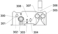
the cloth feeding vapor-liquid spraying box 3 comprises: a cloth inlet vapor-liquid blank cloth 300, a cloth inlet vapor-liquid first cloth guide roller 301, a cloth inlet vapor-liquid deviation correction roller 302, a cloth inlet vapor-liquid photoelectric tube 303, a cloth inlet vapor-liquid second cloth guide roller 304, a cloth inlet vapor-liquid first vapor-liquid spray tube 305, a cloth inlet vapor-liquid air tube 306, a cloth inlet vapor-liquid second vapor-liquid spray tube 307 and a cloth inlet vapor-liquid frame 308; a first cloth guide roller 301 for feeding vapor and liquid is arranged at the upper left corner of a vapor and liquid feeding frame 308, a vapor and liquid feeding deviation correction roller 302 is arranged at the right side of the first cloth guide roller 301 for feeding vapor and liquid, a vapor and liquid feeding photoelectric tube 303 and a vapor and liquid feeding second cloth guide roller 304 are positioned at the middle lower part of the vapor and liquid feeding frame 308, a vapor and liquid feeding first vapor and liquid spraying tube 305 and a vapor and liquid feeding second vapor and liquid spraying tube 307 are arranged at the right side of the vapor and liquid feeding frame 308, and a vapor and liquid feeding air pipe 306 is arranged at the upper right side of the vapor and liquid feeding frame 308;
the first vapor-liquid washing tank 4-1 comprises a vapor-liquid washing gray cloth 400, a vapor-liquid washing observation window 401, a vapor-liquid washing tank 402, a vapor-liquid washing water pump 403, a vapor-liquid washing ball valve 404, a vapor-liquid washing maintenance window 405, a vapor-liquid washing water inlet 406, a vapor-liquid washing air inlet cover 407, a vapor-liquid washing fan 408 and a vapor-liquid washing frame 409; the vapor-liquid washing observation window 401 is located in the middle of a vapor-liquid washing frame 409, the vapor-liquid washing tank 402 is located at the upper right portion of the vapor-liquid washing frame 409, the vapor-liquid washing water pump 403 is located at the lower left portion of the vapor-liquid washing frame 409, the vapor-liquid washing ball valve 404 is located at the lower right portion of the vapor-liquid washing frame 409, the vapor-liquid washing inspection window 405 is located at the right side of the vapor-liquid washing frame 409, the vapor-liquid washing water inlet 406 is located at one side of the vapor-liquid washing observation window 401, the vapor-liquid washing air inlet cover 407 is located at the inner top of the vapor-liquid washing frame 409, and the vapor-liquid washing fan 408 is located at the upper portion of the vapor-liquid washing air inlet cover 407;
the first vapor-liquid washing tank 4-1 is made of fabric which freely slides down under the condition of dead weight and can realize the shape of stacking concentration, the shape can be a slope shape, a funnel shape or a semi-circular arc bottom shape, and a spinning wheel line type is preferably selected in the embodiment;
the first vapor-liquid washing tank 4-1 needs to operate in a micro-positive pressure environment, is resistant to acid and alkali corrosion, is made of 304 stainless steel and 316L stainless steel, is fully welded inside, is polished and subjected to flaw detection and leak detection, and meets the use requirement in a 300Pa micro-positive pressure environment;
the volume of the cloth storage space of the first vapor-liquid washing tank 4-1 meets the requirement that the gram weight of the cloth is 300g/m 2 The cloth storage amount is over 600 meters;
the first vapor-liquid washing tank 4-1 is internally provided with various sensors including but not limited to a temperature sensor, a liquid level sensor, a pH value sensor, a pressure sensor, a position sensor and a weighing sensor, and the vapor-liquid washing access window 405 selects a temperature control type magnetic control switch;
the first vapor-liquid washing tank 4-1 is also provided with a pneumatic proportion regulating valve, a pneumatic two-way valve, a manual butterfly valve and an electric ball valve; all the parts are high-temperature-resistant explosion-proof components;
the structures of the second vapor-liquid washing tank 4-2, the third vapor-liquid washing tank 4-3 and the fourth vapor-liquid washing tank 4-4 are completely the same as the first vapor-liquid washing tank 4-1;
the first vapor-liquid spraying box 5-1 comprises: the device comprises a vapor-liquid spraying gray cloth 500, a vapor-liquid spraying deviation correcting roller 501, a vapor-liquid spraying photoelectric tube 502, a vapor-liquid spraying cloth guide roller 503, a vapor-liquid spraying frame 504, a first vapor-liquid spraying pipe 505, a vapor-liquid spraying first air pipe 506, a second vapor-liquid spraying pipe 507, a third vapor-liquid spraying pipe 508, a vapor-liquid spraying second air pipe 509 and a fourth vapor-liquid spraying pipe 510; the vapor-liquid spraying rectification roller 501 is arranged in the middle of the vapor-liquid spraying frame 504, the vapor-liquid spraying photoelectric tube 502 is positioned on the right side of the vapor-liquid spraying rectification roller 501, the vapor-liquid spraying cloth guide roller 503 is positioned on the right side of the vapor-liquid spraying photoelectric tube 502, the first vapor-liquid spraying pipe 505 and the second vapor-liquid spraying pipe 507 are symmetrically arranged on the right side of the vapor-liquid spraying frame 504, the vapor-liquid spraying first air pipe 506 is arranged on the upper right part of the vapor-liquid spraying frame 504, the third vapor-liquid spraying pipe 508 and the fourth vapor-liquid spraying pipe 510 are symmetrically arranged on the left side of the vapor-liquid spraying frame 504, and the vapor-liquid spraying second air pipe 509 is arranged on the upper left part of the vapor-liquid spraying frame 504;
the second vapor-liquid spraying box 5-2 and the third vapor-liquid spraying box 5-3 have the same structure as the first vapor-liquid spraying box 5-1;
go out cloth vapour liquid spray box 6 includes: the device comprises a cloth discharging gas-liquid blank cloth 600, a cloth discharging gas-liquid deviation correcting roller 601, a cloth discharging gas-liquid photoelectric tube 602, a first cloth guiding roller 603 for discharging gas-liquid, a cloth discharging gas-liquid frame 604, a second cloth guiding roller 605 for discharging gas-liquid, a first gas-liquid spraying pipe 606 for discharging gas-liquid, a first gas-liquid discharging pipe 607 and a second gas-liquid discharging spraying pipe 608; the vapor-liquid outlet correction roller 601 is positioned in the middle of the vapor-liquid outlet frame 604, the vapor-liquid outlet photoelectric tube 602 is positioned on the right side of the vapor-liquid outlet correction roller 601, the first vapor-liquid outlet guide roller 603 is positioned on the right side of the vapor-liquid outlet photoelectric tube 602, the vapor-liquid outlet frame 604 and the second vapor-liquid outlet guide roller 605 are positioned on the left upper side of the vapor-liquid outlet correction roller 601, the first vapor-liquid outlet spray pipe 606 and the second vapor-liquid outlet spray pipe 608 are symmetrically arranged on the left side of the vapor-liquid outlet frame 604, and the first vapor-liquid outlet pipe 607 is positioned on the left upper side of the vapor-liquid outlet frame 604;
the cloth discharging rotary drum washing tank 7 comprises: a fabric outlet drum grey cloth 700, a fabric outlet drum first fabric guide roller 701, a fabric outlet drum first pressure sensor 702, a fabric outlet drum second fabric guide roller 703, a fabric outlet drum water-gas separation tank 704, a fabric outlet drum water pump 705, a fabric outlet drum ball valve 706, a fabric outlet drum third fabric guide roller 707, a fabric outlet drum fourth fabric guide roller 708, a fabric outlet drum pH value sensor 709, a fabric outlet drum temperature sensor 710, a fabric outlet drum steam pipe 711, a fabric outlet drum second pressure sensor 712, a fabric outlet drum roller 713, a fabric outlet drum fifth fabric guide roller 714, a fabric outlet drum sixth fabric guide roller 715, a fabric outlet drum seventh fabric guide roller 716, a fabric outlet drum eighth fabric guide roller 717, a fabric outlet drum filament separating roller 718, a fabric outlet drum padder 719, a fabric outlet drum ninth fabric guide roller 720, a fabric outlet drum tenth fabric guide roller 721, a fabric outlet drum observation window 722, a fabric outlet water spray pipe 723, a fabric outlet drum maintenance window 724, a fabric outlet drum frame 726 and a fabric outlet drum rubber roller 725; a first cloth guide roller 701 of the cloth discharging rotary drum is positioned at the upper left corner of the cloth discharging rotary drum frame 725, a water-gas separation tank 704 of the cloth discharging rotary drum is positioned below the first cloth guide roller 701 of the cloth discharging rotary drum, a first pressure sensor 702 of the cloth discharging rotary drum and a second cloth guide roller 703 of the cloth discharging rotary drum are positioned at the lower part of the water-gas separation tank 704 of the cloth discharging rotary drum, a water pump 705 of the cloth discharging rotary drum is positioned at the lower left part of the cloth discharging rotary drum frame 725, a ball valve 706 of the cloth discharging rotary drum is positioned at the right side of the water pump 705 of the cloth discharging rotary drum, and a third cloth guide roller 707 of the cloth discharging rotary drum, a fourth cloth guide roller 708 of the cloth discharging rotary drum and a fifth cloth guide roller 714 of the cloth discharging rotary drum are obliquely and sequentially arranged; a cloth outlet drum roller 713 is arranged in the middle of the cloth outlet drum frame 725, a cloth outlet drum pH value sensor 709, a cloth outlet drum temperature sensor 710, a cloth outlet drum steam pipe 711 and a cloth outlet drum second pressure sensor 712 are sequentially arranged at the lower part of the cloth outlet drum roller 713, a cloth outlet drum sixth cloth guide roller 715, a cloth outlet drum seventh cloth guide roller 716, a cloth outlet drum eighth cloth guide roller 717 and a cloth outlet drum dividing roller 718 are obliquely and sequentially arranged at the upper right of the cloth outlet drum roller 713, a cloth outlet drum padder 719 is arranged at the upper right corner of the cloth outlet drum frame 725, a cloth outlet drum ninth cloth guide roller 720 and a cloth outlet drum tenth cloth guide roller 721 are arranged at the upper right of the cloth outlet drum frame 725, a cloth outlet drum observation window 722 is arranged above the cloth outlet drum roller 713, a cloth outlet drum sprinkling pipe 723 is arranged above the cloth outlet drum observation window 722, a cloth outlet drum overhaul window 724 is arranged at the upper part of the cloth outlet drum frame 725, and a cloth outlet drum water-separating tank 704 is arranged at the upper right of the cloth outlet drum gas-separating tank 704;
the cloth discharging and falling assembly 8 comprises: the device comprises a cropping grey cloth 800, a cropping first smooth roller 801, a cropping second smooth roller 802, a cropping roller 803, a cropping first cloth guide roller 804, a speed reducer 805, a cropping second cloth guide roller 806, a cropping first cloth guide roller 807, a cropping second cloth guide roller 808, a vacuum water absorption device 809, a cropping third cloth guide roller 810 and a cropping frame 811; the first doffing smooth roller 801, the second doffing smooth roller 802 and the doffing roller 803 are positioned at the front end spiral arm of a doffing frame 811, the first doffing cloth guide roller 804, the speed reducer 805 and the second doffing cloth guide roller 806 are sequentially positioned at the front arm of the doffing frame 811, the first doffing cloth guide roller 807 and the second doffing cloth guide roller 808 are arranged at the middle upper part of the doffing frame 811, a vacuum water absorption device 809 is arranged at the left upper part of the doffing frame 811, and a third doffing cloth guide roller 810 is arranged at the left side of the vacuum water absorption device 809;
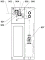
the vacuum water absorption device 809 comprises: a first vacuum square tube 901, a first vacuum connecting tube 902, a first edge-tracing mechanism 903, a second vacuum connecting tube 904, a second vacuum square tube 905, a second edge-tracing mechanism 906 and a vacuum pump 907; a first vacuum square pipe 901, a first vacuum connecting pipe 902, a first edge-tracing mechanism 903, a second vacuum connecting pipe 904, a second vacuum square pipe 905 and a second edge-tracing mechanism 906 are fixed on a cropping frame 811, the first vacuum connecting pipe 902 is connected with the first vacuum square pipe 901 and a vacuum pump 907, the first edge-tracing mechanism 903 is installed right above the first vacuum square pipe 902, the second vacuum connecting pipe 904 is connected with the second vacuum square pipe 905 and the vacuum pump 907, the second edge-tracing mechanism 906 is installed right below the second vacuum square pipe 905, and the vacuum pump 907 is installed at the right lower bottom of the cropping frame 811.
The utility model discloses a shuttle/knitting high-efficient vapour liquid open width water washing system of high temperature's process steps as follows:
(1) Deviation rectification of grey cloth (refers to an uncolored semi-finished product and is generally called as grey cloth), wherein the grey cloth is rectified through a centering deviation rectification roller on a cloth feeding and liquid feeding box and a water washing cloth feeding frame, so that the problem of cloth deviation caused by various reasons is solved;
(2) The corrected grey cloth enters a cloth feeding and liquid feeding box and an auxiliary agent box to be subjected to drum washing pretreatment and liquid squeezing, and the auxiliary agents comprise degreasing agents, detergents, scouring agents and the like and are used for improving the appearance or physical properties of the grey cloth;
(3) The pretreated gray fabric is discharged from the fabric feeding and liquid feeding box, enters a drum washing box, and is subjected to three-in-one washing design of submerged soaking, oscillating washing and spraying washing to remove oil in fabric fibers, metal ions on the fabric surface, wool and other impurities;
(4) The grey cloth after drum washing enters a cloth inlet steam-liquid spraying box, and a high-temperature steam-liquid mixture with the speed as high as 25-40 m/s can be sprayed out through an air spraying water washing pipe assembly in the cloth inlet steam-liquid spraying box, so that not only can the pneumatic conveying of the grey cloth be realized when the grey cloth passes through the high-temperature steam-liquid mixture, but also the strong oscillation impact of the grey cloth in the direction of a nozzle of the air spraying water washing pipe assembly can be formed, and the rapid and violent shaking of the fabric can be formed; then, the gray cloth slides freely under the condition of self weight and is stacked in a cloth accumulating groove of a vapor-liquid washing tank, and the cloth accumulating amount of the cloth accumulating groove can reach as high as 600m, so that the gray cloth can be soaped and steamed for a long time in the groove, and the boiling and desizing process is realized; the adjacent subsequent vapor-liquid washing tank carries out washing liquid countercurrent on the vapor-liquid washing tank in the previous process through the water replenishing pump, so that the utilization rate of the washing liquid is improved, and the water consumption is reduced; the number of the sections of the vapor-liquid washing tank is different according to the gray fabric process, and can be 2-8 sections which are arranged in series;
(5) The washed grey cloth comes out of the fourth vapor-liquid washing tank and enters a rotary drum washing tank for neutralization rinsing;
(6) The grey cloth passes through a rotary drum washing tank, passes through a cloth discharging assembly and a vacuum water absorption device to remove excessive moisture in the grey cloth, and is discharged through a cloth discharging roller and a cloth discharging roller.
The utility model discloses a shuttle/knitting high-efficient vapour liquid open width rinse-system of knitting high temperature has following characteristics:
(1) Is suitable for various water washing processes; the modular design and the building block type structure can be combined and matched with mechanical equipment flows at will according to different products and process requirements; the desizing, scouring and bleaching can be carried out on cotton, polyester, hemp and blended fabrics, so that the fabrics have better whiteness, capillary effect and softness; and can be used for washing after dyeing and after printing.
(2) The high-quality washing effect is realized; the open-width vapor-liquid impact treatment process has the advantages of strong vapor-liquid penetrability, uniform impact beating force and good consistency in all areas of cloth, high bulkiness of the rinsed cloth surface, good softness, good hand feeling, good capillary effect, no friction trace and the like.
(3) The equipment structure is compact, and the occupied area is small; the traditional steaming box is replaced by the countercurrent low-water-level strong-spraying-rolling and high-temperature steam-liquid-hot air mixed airflow, and the traditional loose-pile spraying type washing box is replaced by the high-capacity cloth storage tank and the efficient soap boiling function, so that the equipment is short in flow and small in occupied area.
(4) The pre-shrinking effect is natural; the main washing process equipment adopts high-temperature high-efficiency vapor-liquid open-width washing, is driven by wind power, has low tension, uniform and stable temperature in a washing tank, natural and full preshrinking of fabrics, small deformation, fine denier of fabrics and natural arrangement.
(5) The cleaning efficiency is high; the washing method comprises the steps of multi-groove washing liquor water replenishing and countercurrent, powerful spraying, multi-soaking and multi-rolling, rotary drum oscillation, high-temperature steaming and washing, high-speed steam-liquid impact beating, soap boiling action time prolonging, and the washing efficiency is improved by jointly acting on the fabric.
(6) The water and steam consumption is low, and the energy consumption is low; the design of low water level and small bath ratio ensures that the washing liquid is replaced quickly and utilized more fully, is beneficial to the diffusion of dirt on the fabric to the washing liquid, and has less water and steam consumption; the cloth inlet and outlet are sealed by lotion, the local high temperature of the normal pressure nozzle in the washing tank can reach 130 ℃, the running time of the fabric in the steam area is longer, the hot air and the hot water are both circulated in the equipment, the temperature in the washing tank is stable, the heat source only performs temperature compensation, and the energy consumption is very low.
The utility model discloses an among the high-efficient vapour liquid open width water washing system of shuttle weaving/knitting high temperature, washing equipment is applicable to cotton moves back to boil and floats and gives good mao effect and whiteness degree of fabric, also is applicable to the chemical fibre and gets rid of the finish that adds in the preceding spinning technology, weaves the dirt and other impurity of thick liquids, adhesion, makes the fabric clean and tidy, lays a good foundation for the later process dyeing, also is applicable to the acid stamp fabric washing and the dyeing washing of easily staining simultaneously.
The utility model is used for shuttle/knitting high-efficient vapour liquid open width washing equipment's of high temperature main innovation point is: (1) compatible and applicable to various water washing processes; (2) the high-quality washing effect can be realized; (3) the equipment structure is compact, and the occupied area is small; (4) a natural preshrinking effect can be realized; (5) the cleaning efficiency is high; (6) the water and steam consumption is low, and the energy consumption is low.
The above description is only the specific implementation manner of the preferred embodiment of the present invention, but the protection scope of the present invention is not limited thereto, and any person skilled in the art can substitute or change the technical solution of the present invention and the design of the present invention within the technical scope of the present invention.
Claims (10)
1. The utility model provides a shuttle/knitting high-efficient vapour liquid open width water washing system which characterized in that: comprises a cloth feeding and liquid feeding box, a cloth feeding rotary drum washing box, a cloth feeding vapor-liquid spraying box, a vapor-liquid washing box, a vapor-liquid spraying box, a cloth discharging rotary drum washing box and a cloth discharging assembly; the above parts are connected in sequence: the cloth feeding and feeding tank is connected with the cloth feeding rotary drum washing tank, the cloth feeding rotary drum washing tank is connected with the cloth feeding vapor-liquid spraying tank, the cloth feeding vapor-liquid spraying tank is connected with the vapor-liquid washing tank, the vapor-liquid washing tank is connected with the vapor-liquid spraying tank, the vapor-liquid spraying tank is connected with the second vapor-liquid washing tank, the second vapor-liquid washing tank is connected with the cloth discharging vapor-liquid spraying tank, the cloth discharging vapor-liquid spraying tank is connected with the cloth discharging rotary drum washing tank, and the cloth discharging rotary drum washing tank is connected with the cloth discharging assembly;
the cloth feeding vapor-liquid spraying box comprises: the device comprises a cloth feeding vapor-liquid blank cloth, a cloth feeding vapor-liquid first cloth guide roller, a cloth feeding vapor-liquid deviation correction roller, a cloth feeding vapor-liquid photoelectric tube, a cloth feeding vapor-liquid second cloth guide roller, a cloth feeding vapor-liquid first vapor-liquid spray pipe, a cloth feeding vapor-liquid air pipe, a cloth feeding vapor-liquid second vapor-liquid spray pipe and a cloth feeding vapor-liquid frame; the first cloth guide roller for feeding the cloth vapor and liquid is arranged at the upper left corner of the frame for feeding the cloth vapor and liquid, the deviation correction roller for feeding the cloth vapor and liquid is arranged at the right side of the first cloth guide roller for feeding the cloth vapor and liquid, the photoelectric tube for feeding the cloth vapor and liquid and the second cloth guide roller for feeding the cloth vapor and liquid are arranged at the middle lower part of the frame for feeding the cloth vapor and liquid, the first vapor and liquid spray pipe for feeding the cloth vapor and liquid and the second vapor and liquid spray pipe for feeding the cloth vapor and liquid are arranged at the right side of the frame for feeding the cloth vapor and liquid, and the air pipe for feeding the cloth vapor and liquid is arranged at the upper right side of the frame for feeding the cloth vapor and liquid;
the vapor-liquid washing tank and the second vapor-liquid washing tank comprise vapor-liquid washing gray cloth, a vapor-liquid washing observation window, a vapor-liquid washing tank, a vapor-liquid washing water pump, a vapor-liquid washing ball valve, a vapor-liquid washing overhaul window, a vapor-liquid washing water inlet, a vapor-liquid washing air inlet cover, a vapor-liquid washing fan and a vapor-liquid washing frame; the vapor-liquid washing inspection window is positioned in the middle of the vapor-liquid washing frame, the vapor-liquid washing tank is positioned at the upper right part of the vapor-liquid washing frame, the vapor-liquid washing water pump is positioned at the lower left part of the vapor-liquid washing frame, the vapor-liquid washing ball valve is positioned at the lower right part of the vapor-liquid washing frame, the vapor-liquid washing inspection window is positioned at the right side of the vapor-liquid washing frame, the vapor-liquid washing water inlet is positioned at one side of the vapor-liquid washing inspection window, the vapor-liquid washing air inlet cover is positioned at the inner side of the top of the vapor-liquid washing frame, and the vapor-liquid washing fan is positioned at the upper part of the vapor-liquid washing air inlet cover;
the vapour-liquid sprays the case and includes: the device comprises a vapor-liquid spraying gray cloth, a vapor-liquid spraying deviation correcting roller, a vapor-liquid spraying photoelectric tube, a vapor-liquid spraying cloth guide roller, a vapor-liquid spraying frame, a first vapor-liquid spraying tube, a vapor-liquid spraying first air pipe, a second vapor-liquid spraying tube, a third vapor-liquid spraying tube, a vapor-liquid spraying second air pipe and a fourth vapor-liquid spraying tube; the vapor-liquid spraying correction roller is installed in the middle of the vapor-liquid spraying frame, the vapor-liquid spraying photoelectric tube is located on the right side of the vapor-liquid spraying correction roller, the vapor-liquid spraying cloth guide roller is located on the right side of the vapor-liquid spraying photoelectric tube, the first vapor-liquid spraying tube and the second vapor-liquid spraying tube are symmetrically installed on the right side of the vapor-liquid spraying frame, the vapor-liquid spraying first air pipe is installed on the upper right portion of the vapor-liquid spraying frame, the third vapor-liquid spraying tube and the fourth vapor-liquid spraying tube are symmetrically installed on the left side of the vapor-liquid spraying frame, and the vapor-liquid spraying second air pipe is installed on the upper left portion of the vapor-liquid spraying frame.
2. The woven/knitted high temperature high efficiency vapor liquid open width water wash system of claim 1, wherein: the cloth feeding and liquid feeding box comprises a blank cloth, a cloth feeding and liquid feeding water pump, an auxiliary agent box, a cloth feeding and liquid feeding first ball valve, a cloth feeding and liquid feeding second ball valve, a soaking box, a spray pipe, a cloth feeding and liquid feeding first cloth guide roller, a cloth feeding and liquid feeding first filament dividing roller, a cloth feeding and liquid feeding padder, an access door, a cloth feeding and liquid feeding first rubber roller, a cloth feeding and liquid feeding second cloth guide roller, a cloth feeding and liquid feeding third cloth guide roller, a cloth feeding and liquid feeding photoelectric tube, a cloth feeding and liquid feeding first deviation correction roller, a cloth feeding and liquid feeding second filament dividing roller, a cloth feeding and liquid feeding third filament dividing roller, a cloth feeding and liquid feeding fourth cloth guide roller, a cloth feeding and liquid feeding fifth cloth guide roller, a cloth feeding and liquid feeding sixth cloth guide roller, a cloth feeding and liquid feeding seventh cloth guide roller, a cloth feeding and liquid feeding limit roller, a cloth feeding eighth cloth guide roller and a cloth feeding and liquid feeding frame; the cloth feeding water pump is positioned on one side of the bottom of the cloth feeding water frame, the auxiliary agent box is positioned above the cloth feeding water pump, the cloth feeding water feeding first ball valve is positioned in the middle of the auxiliary agent box, the cloth feeding water feeding second ball valve is positioned on the right upper part of the auxiliary agent box, the soaking box is positioned above the auxiliary agent box and is connected with the auxiliary agent box through a pipeline, the spray pipe is positioned on the right side of the soaking box, the cloth feeding water feeding first rubber roller is positioned in the middle of the soaking box, the cloth feeding water feeding first cloth guiding roller and the cloth feeding water feeding second cloth guiding roller are positioned on two sides of the cloth feeding water feeding first rubber roller, the cloth feeding water feeding first branching roller is positioned on the right upper part of the cloth feeding liquid feeding first cloth guiding roller, the cloth feeding and liquid feeding padder is positioned on the right side of the cloth feeding and liquid feeding first wire dividing roller, the access door is positioned on the right upper side of the cloth feeding and liquid feeding frame, the cloth feeding and liquid feeding third cloth guide roller is positioned on the left side of the cloth feeding and liquid feeding second cloth guide roller, the cloth feeding and liquid feeding photoelectric tube is positioned above the cloth feeding and liquid feeding third cloth guide roller, the cloth feeding and liquid feeding first deviation correction roller is positioned above the left side of the cloth feeding and liquid feeding photoelectric tube, the cloth feeding and liquid feeding second wire dividing roller, the cloth feeding and liquid feeding third wire dividing roller, the cloth feeding and liquid feeding fourth cloth guide roller, the cloth feeding and liquid feeding fifth cloth guide roller, the cloth feeding and liquid feeding sixth cloth guide roller, the cloth feeding and liquid feeding seventh cloth guide roller, the cloth feeding and liquid feeding limit roller and the cloth feeding and liquid feeding eighth cloth guide roller are sequentially arranged from right to left.
3. The woven/knitted high temperature high efficiency vapor liquid open width water wash system of claim 1, wherein: the cloth feeding rotary drum washing box comprises rotary drum grey cloth, a first cloth guide roller of the rotary drum, a second cloth guide roller of the rotary drum, a third cloth guide roller of the rotary drum, a rubber covered roller of the rotary drum, a fourth cloth guide roller of the rotary drum, a water-gas separation tank of the rotary drum, a fifth cloth guide roller of the rotary drum, a sixth cloth guide roller of the rotary drum, a seventh cloth guide roller of the rotary drum, a water pump of the rotary drum, a pH value sensor of the rotary drum, a temperature sensor of the rotary drum, a steam pipe of the rotary drum, a pressure sensor of the rotary drum, a washing tank of the rotary drum, a drum roller, an eighth cloth guide roller of the rotary drum, a ninth cloth guide roller of the rotary drum, a tenth cloth guide roller of the rotary drum, a silk dividing roller of the rotary drum, a rolling mill of the rotary drum, a water spraying pipe of the rotary drum, an observation window of the rotary drum, an overhaul window of the rotary drum and a frame of the rotary drum; the device comprises a first fabric guide roller of a rotary drum, a second fabric guide roller of the rotary drum, a third fabric guide roller of the rotary drum and a fourth fabric guide roller of the rotary drum, which are respectively arranged at the upper left corner of a rotary drum frame from top to bottom, a water-gas separation groove of the rotary drum is positioned below the third fabric guide roller of the rotary drum, a rubber roll of the rotary drum is positioned at the upper right corner of the water-gas separation groove of the rotary drum, a fifth fabric guide roller of the rotary drum, a sixth fabric guide roller of the rotary drum and a seventh fabric guide roller of the rotary drum are sequentially positioned at the lower right corner of the rubber roll to form a diagonal arrangement, a water pump of the rotary drum is arranged at the lower left corner of the rotary drum frame, a pH value sensor of the rotary drum, a temperature sensor of the rotary drum, a steam pipe of the rotary drum and a pressure sensor of the rotary drum are sequentially arranged at the bottom of the water washing groove of the rotary drum, a rotary drum is positioned at the middle of the rotary drum frame, a rotary drum roller is arranged at the middle of the water washing groove of the rotary drum, an eighth fabric guide roller, a ninth fabric guide roller, a tenth fabric guide roller of the rotary drum, a fiber dividing roller of the rotary drum is sequentially arranged at the upper part of the water washing groove of the rotary drum, and a top of the rotary drum is arranged at the top of the rotary drum.
4. The woven/knitted high temperature high efficiency vapor liquid open width water wash system of claim 1, wherein: the fabric of the vapor-liquid water washing tank and the second vapor-liquid water washing tank freely slides under the condition of dead weight, and can be made into a stacked and concentrated shape, wherein the shape is a slope shape, a funnel shape, a semi-circular arc bottom shape or a spinning wheel line shape.
5. The woven/knitted high temperature high efficiency vapor liquid open width water wash system of claim 1, wherein: the vapor-liquid washing inspection windows in the vapor-liquid washing tank and the second vapor-liquid washing tank select temperature control type magnetic control switches; the vapor-liquid washing tank and the second vapor-liquid washing tank are also provided with a pneumatic proportional regulating valve, a pneumatic two-way valve, a manual butterfly valve and an electric ball valve; all the components are high-temperature-resistant explosion-proof components.
6. The woven/knitted high temperature high efficiency vapor liquid open width water wash system of claim 1, wherein: the device also comprises a third vapor-liquid water washing tank and a fourth vapor-liquid water washing tank, and the structure of the third vapor-liquid water washing tank is completely the same as that of the fourth vapor-liquid water washing tank; the structure of the second vapor-liquid spraying box is completely the same as that of the vapor-liquid spraying box; the vapor-liquid water washing tank is connected with the vapor-liquid water washing tank, the vapor-liquid water washing tank is connected with the second vapor-liquid water washing tank, the second vapor-liquid water washing tank is connected with the third vapor-liquid water washing tank, the third vapor-liquid water washing tank is connected with the fourth vapor-liquid water washing tank, and the fourth vapor-liquid water washing tank is connected with the vapor-liquid water washing tank.
7. The woven/knitted high temperature high efficiency vapor liquid open width water wash system of claim 1, wherein: go out cloth vapour and liquid and spray the case and include: the device comprises a cloth discharging and distributing vapor-liquid blank cloth, a cloth discharging and distributing vapor-liquid deviation correcting roller, a vapor discharging and distributing liquid photoelectric tube, a vapor discharging and distributing liquid first cloth guide roller, a vapor discharging and distributing liquid frame, a vapor discharging and distributing liquid second cloth guide roller, a vapor discharging and distributing liquid first vapor-liquid spraying tube, a vapor discharging and distributing liquid first air pipe and a vapor discharging and distributing liquid second vapor-liquid spraying tube; go out cloth vapour and liquid and rectify the roller and be located the middle part of a cloth vapour and liquid frame, go out cloth vapour and liquid photoelectric tube and be located the right side that goes out cloth vapour and liquid and rectify the roller, go out the first cloth guide roller of cloth vapour and liquid and be located the right side that goes out cloth vapour and liquid photoelectric tube, go out cloth vapour and liquid frame, go out cloth vapour and liquid second cloth guide roller and be located the upper left side that goes out cloth vapour and liquid and rectify the roller, go out the first vapour and liquid of cloth vapour and liquid and spout the pipe symmetry of drenching and install in the left side that goes out cloth vapour and liquid frame that goes out the first tuber pipe of cloth vapour and liquid is located the upper left side that goes out cloth vapour and liquid frame.
8. The woven/knitted high temperature high efficiency vapor liquid open width water wash system of claim 1, wherein: the cloth discharging rotary drum washing tank comprises: a fabric outlet rotary drum blank cloth, a fabric outlet rotary drum first fabric guide roller, a fabric outlet rotary drum first pressure sensor, a fabric outlet rotary drum second fabric guide roller, a fabric outlet rotary drum water-vapor separation tank, a fabric outlet rotary drum water pump, a fabric outlet rotary drum ball valve, a fabric outlet rotary drum third fabric guide roller, a fabric outlet rotary drum fourth fabric guide roller, a fabric outlet rotary drum pH value sensor, a fabric outlet rotary drum temperature sensor, a fabric outlet rotary drum steam pipe, a fabric outlet rotary drum second pressure sensor, a fabric outlet rotary drum roller, a fabric outlet rotary drum fifth fabric guide roller, a fabric outlet rotary drum sixth fabric guide roller, a fabric outlet rotary drum seventh fabric guide roller, a fabric outlet rotary drum eighth fabric guide roller, a fabric outlet rotary drum filament dividing roller, a fabric outlet rotary drum rolling vehicle, a fabric outlet rotary drum ninth fabric guide roller, a fabric outlet rotary drum tenth fabric guide roller, a fabric outlet rotary drum observation window, a fabric outlet rotary drum water spraying pipe, a fabric outlet rotary drum maintenance window, a fabric outlet rotary drum frame and a fabric outlet rotary drum; a first cloth guide roller of the cloth discharging rotary drum is positioned at the upper left corner of the cloth discharging rotary drum frame, a water-gas separation groove of the cloth discharging rotary drum is positioned below the first cloth guide roller of the cloth discharging rotary drum, a first pressure sensor of the cloth discharging rotary drum and a second cloth guide roller of the cloth discharging rotary drum are positioned at the lower part of the water-gas separation groove of the cloth discharging rotary drum, a water pump of the cloth discharging rotary drum is positioned at the lower left part of the cloth discharging rotary drum frame, a ball valve of the cloth discharging rotary drum is positioned at the right side of the water pump of the cloth discharging rotary drum, and a third cloth guide roller of the cloth discharging rotary drum, a fourth cloth guide roller of the cloth discharging rotary drum and a fifth cloth guide roller of the cloth discharging rotary drum are obliquely and sequentially arranged; the cloth discharging rotary drum roller is arranged in the middle of the cloth discharging rotary drum frame, the cloth discharging rotary drum pH value sensor, the cloth discharging rotary drum temperature sensor, the cloth discharging rotary drum steam pipe and the cloth discharging rotary drum second pressure sensor are sequentially arranged on the lower portion of the cloth discharging rotary drum roller, a sixth cloth guide roller, a seventh cloth guide roller, an eighth cloth guide roller and a cloth discharging rotary drum filament separating roller of the cloth discharging rotary drum are obliquely and sequentially arranged on the upper right of the cloth discharging rotary drum roller, the cloth discharging rotary drum padder is arranged on the upper right corner of the cloth discharging rotary drum frame, a ninth cloth guide roller and a tenth cloth guide roller of the cloth discharging rotary drum are arranged on the upper right of the cloth discharging rotary drum frame, the cloth discharging rotary drum observation window is positioned above the cloth discharging rotary drum roller, the cloth discharging rotary drum water spraying pipe is positioned above the cloth discharging rotary drum observation window, the cloth discharging rotary drum maintenance window is positioned on the upper portion of the cloth discharging rotary drum frame, and the cloth discharging rotary drum rubber roll is arranged on the upper right of the cloth discharging rotary drum water-gas separation tank.
9. The woven/knitted high-temperature high-efficiency vapor-liquid open-width water washing system according to claim 1, wherein: the fall-out assembly comprises: the device comprises a cloth discharging and falling device, a cloth discharging and falling first smooth roller, a cloth discharging and falling second smooth roller, a cloth falling roller, a cloth discharging and falling first cloth guide roller, a speed reducer, a cloth discharging and falling second cloth guide roller, a cloth discharging and falling first cloth outlet roller, a cloth discharging and falling second cloth outlet roller, a vacuum water absorption device, a cloth discharging and falling third cloth guide roller and a cloth discharging and falling frame; the first falling cloth outlet smooth roller, the second falling cloth outlet smooth roller and the falling cloth roller are positioned at the front end spiral arm of the falling cloth outlet frame, the first falling cloth outlet guide roller, the speed reducer and the second falling cloth outlet guide roller are sequentially positioned on the front arm of the falling cloth outlet frame, the first falling cloth outlet roller and the second falling cloth outlet roller are arranged on the middle upper portion of the falling cloth outlet frame, the vacuum water absorption device is arranged on the left upper portion of the falling cloth outlet frame, and the third falling cloth outlet guide roller is arranged on the left side of the vacuum water absorption device.
10. The woven/knitted high temperature high efficiency vapor liquid open width water wash system of claim 9, wherein: the vacuum water absorption device comprises: the device comprises a first vacuum square tube, a first vacuum connecting tube, a first edge chasing mechanism, a second vacuum connecting tube, a second vacuum square tube, a second edge chasing mechanism and a vacuum pump; the first vacuum side pipe, the first vacuum connecting pipe, the first edge chasing mechanism, the second vacuum connecting pipe, the second vacuum side pipe and the second edge chasing mechanism are fixed on the falling cloth frame, the first vacuum connecting pipe is connected with the first vacuum side pipe and the vacuum pump, the first edge chasing mechanism is installed right above the first vacuum side pipe, the second vacuum connecting pipe is connected with the second vacuum side pipe and the vacuum pump, the second edge chasing mechanism is installed right below the second vacuum side pipe, and the vacuum pump is installed at the bottom right below the falling cloth frame.
Priority Applications (1)
| Application Number | Priority Date | Filing Date | Title |
|---|---|---|---|
| CN202222066720.0U CN218147291U (en) | 2022-08-08 | 2022-08-08 | High-temperature efficient vapor-liquid open-width washing system for tatting/knitting |
Applications Claiming Priority (1)
| Application Number | Priority Date | Filing Date | Title |
|---|---|---|---|
| CN202222066720.0U CN218147291U (en) | 2022-08-08 | 2022-08-08 | High-temperature efficient vapor-liquid open-width washing system for tatting/knitting |
Publications (1)
| Publication Number | Publication Date |
|---|---|
| CN218147291U true CN218147291U (en) | 2022-12-27 |
Family
ID=84599488
Family Applications (1)
| Application Number | Title | Priority Date | Filing Date |
|---|---|---|---|
| CN202222066720.0U Active CN218147291U (en) | 2022-08-08 | 2022-08-08 | High-temperature efficient vapor-liquid open-width washing system for tatting/knitting |
Country Status (1)
| Country | Link |
|---|---|
| CN (1) | CN218147291U (en) |
-
2022
- 2022-08-08 CN CN202222066720.0U patent/CN218147291U/en active Active
Similar Documents
| Publication | Publication Date | Title |
|---|---|---|
| CN103205835B (en) | Nano-silver antibacterial shirt fabric and preparation method for same | |
| CN101117748B (en) | High-count flax ramie fibre mixed fabrics and production technique | |
| CN106087309B (en) | A kind of knitting open width mercerizing machine | |
| CN106676793A (en) | Continuous open-width cloth boiling system | |
| CN211772006U (en) | Cotton yarn cleaning and drying device | |
| CN206538578U (en) | A kind of cold rolling steam continuous dyeing equipment of denim yarn reactive dye | |
| CN218147291U (en) | High-temperature efficient vapor-liquid open-width washing system for tatting/knitting | |
| CN110670268A (en) | Cleaning device for textile fabric | |
| CN212983293U (en) | Water washing system | |
| CN212983269U (en) | Water circulation system of washing machine | |
| CN212983268U (en) | Water circulation system of washing machine | |
| CN213113884U (en) | Water washing machine | |
| CN210287774U (en) | Integrated processing equipment for textile fabrics | |
| CN107012632A (en) | A kind of printed fabrics gas singeing machine | |
| CN113668164A (en) | Water washing unit simultaneously provided with rotary drum rotor mechanism and guide roller | |
| CN208087916U (en) | A kind of fabric decontamination apparatus | |
| CN218147292U (en) | High-temperature high-efficiency vapor-liquid open-width washing module structure in textile printing and dyeing industry | |
| CN112760880A (en) | Uniform dye liquor spinning, dyeing and finishing integrated production system | |
| CN112779707A (en) | Non-color-difference integrated production system for textile dyeing and finishing | |
| CN115323659B (en) | High-temperature high-efficiency vapor-liquid open-width rinsing machine for textile printing and dyeing industry | |
| CN205874731U (en) | High -efficiency energy -saving desizing machine | |
| CN1114698A (en) | Method and equipment for quick scouring and bleaching process before printing and dyeing | |
| CN217127759U (en) | Double-layer fabric washing combination machine | |
| CN114575016B (en) | Preparation method of anti-velvet light and thin fabric | |
| CN109554862A (en) | A kind of bleaching system for cotton production line of weaving |
Legal Events
| Date | Code | Title | Description |
|---|---|---|---|
| GR01 | Patent grant | ||
| GR01 | Patent grant |