CN218074846U - Base station for cleaning machine and cleaning system - Google Patents
Base station for cleaning machine and cleaning system Download PDFInfo
- Publication number
- CN218074846U CN218074846U CN202221591078.1U CN202221591078U CN218074846U CN 218074846 U CN218074846 U CN 218074846U CN 202221591078 U CN202221591078 U CN 202221591078U CN 218074846 U CN218074846 U CN 218074846U
- Authority
- CN
- China
- Prior art keywords
- piece
- base station
- cleaning
- scraping
- groove
- Prior art date
- Legal status (The legal status is an assumption and is not a legal conclusion. Google has not performed a legal analysis and makes no representation as to the accuracy of the status listed.)
- Active
Links
Images


Abstract
The utility model relates to a base station for a cleaning machine and a cleaning system, the base station for the cleaning machine comprises a base, wherein the base is internally provided with an accommodating cavity with an opening at the front side for the cleaning machine to enter; the scraping piece is positioned in the accommodating cavity, is arranged on the bottom wall of the accommodating cavity and can rotate relative to the base; the method is characterized in that: the bottom of the scraping piece is provided with a cleaning piece used for cleaning the bottom wall of the accommodating cavity. At scraper pivoted in-process, the clearance piece can be cleared up the diapire of holding chamber, prevents that rubbish from adhering on the diapire of holding chamber in long-term use, has improved the clean effect to the holding chamber diapire, and prevents to produce the peculiar smell, has improved user's experience.
Description
Technical Field
The utility model belongs to the technical field of domestic cleanness, washing, concretely relates to a basic station and clean system for cleaning machine.
Background
Current cleaners are used to draw into their interior a mixture of dirt, etc. mixed with moisture on the floor.
In order to timely discharge garbage in an inner cavity of a cleaning machine or clean a brush head of the cleaning machine, a base station is usually arranged, and the current base station is used for cleaning a mop cloth of a sweeper, such as a cleaning device in Chinese utility model patent No. ZL202020859348.7 (with the publication number CN 212939601U), and the cleaning device comprises a base, a spray cleaning component and a scraping cleaning component. The base is provided with a cleaning position for cleaning the mop of the sweeper, the cleaning position is concavely provided with a cleaning groove, and when the sweeper is positioned at the cleaning position, the mop of the sweeper is opposite to the cleaning groove; the spray washing component is arranged on the base and is provided with a spray head for spraying cleaning solution to a mop of the sweeper; the scraping and washing assembly comprises a driving assembly and a scraping strip, the scraping strip is arranged in the cleaning groove, and the driving assembly is in driving connection with the scraping strip so as to drive the scraping strip to scrape and wash the mop. The base is used for bearing the sweeper, and the spray head in the spray washing assembly sprays cleaning liquid to the mop cloth so as to soak the mop cloth.
Although the above patent can realize scraping and spray cleaning the mop of the sweeper, the cleaned garbage falls into the cleaning groove, and in the long-term use process, the garbage is easily adhered to the wall plate of the cleaning groove, so that the cleaning difficulty is increased.
Therefore, further improvements to existing base stations are needed.
SUMMERY OF THE UTILITY MODEL
The utility model discloses the first technical problem that will solve is to above-mentioned prior art's current situation, provides a convenient basic station that carries out abluent being used for cleaning machine to the basic station chassis.
The utility model aims to solve the second technical problem that, a clean system that can clear up the cleaner brush head automatically is provided.
The utility model provides a technical scheme that above-mentioned first technical problem adopted does: a base station for a cleaning machine, comprising:
the cleaning machine comprises a base, a cleaning machine and a cleaning machine, wherein the base is internally provided with an accommodating chamber with an opening at the front side for the cleaning machine to enter;
the scraping piece is positioned in the accommodating cavity, is arranged on the bottom wall of the accommodating cavity and can rotate relative to the base;
the method is characterized in that: the bottom of the scraping piece is provided with a cleaning piece used for cleaning the bottom wall of the accommodating chamber.
The cleaning member takes one of the forms: the scraper is a flexible scraper strip which is integrally in a strip shape, the cleaning piece is a flexible scraper plate which is vertically arranged, and the flexible scraper plate extends along the length direction of the scraper.
The cleaning piece adopts the second form: the scraper is a whole strip-shaped flexible scraper strip, the cleaning piece is a vertically extending flexible brush column, and the flexible brush columns are arranged in a plurality of intervals along the length direction of the scraper.
In order to facilitate the positioning of the mops of the subsequent cleaning machine therein, the bottom wall of the accommodating chamber is provided with a groove which is concave downwards, the scraper can be rotatably arranged in the groove, and the bottom of the cleaning piece is contacted with the bottom wall of the groove. In addition, the existence of recess can prevent that rubbish from overflowing to outside the recess to reliably clear up the diapire of recess.
The cross-section of the recess may be circular or non-circular, but preferably the cross-section of the recess is circular for receiving a mop of the cleaning machine therein.
In order to discharge the cleaned garbage into the sewage draining port in time, the bottom wall of the accommodating cavity is provided with the sewage draining port, and the sewage draining port is located on a rotating path of the cleaning piece or the scraping piece.
Preferably, the scrapers are two in number and are arranged at intervals in the left-right direction. In this way, a cleaning machine with two mops can be adapted, one mop for each wiper, which can be cleaned.
Further preferably, the bottom wall of the accommodating chamber is provided with a groove which is sunken downwards, each scraper is correspondingly provided with a groove, the scrapers can be rotatably arranged in the grooves, and the sewage draining port is positioned between the two grooves and communicated with the grooves.
The drain can set up outside the recess, and be close to the open position in front side, also can set up in the position that the accommodation chamber is close to the back wallboard, but preferably, the drain is located wallboard and two behind the accommodation chamber in the space that the recess encloses.
In order to realize the unidirectional rotation of the scraping piece, a positioning structure which can enable the scraping piece to rotate unidirectionally relative to the base is arranged between the scraping piece and the bottom wall of the base.
The positioning structure has various structural forms, but preferably, the positioning structure comprises a connecting piece fixedly arranged on the bottom wall of the base, an elastic piece and a pawl capable of enabling the scraper to rotate in a single direction relative to the connecting piece, the bottom of the scraper is provided with a mounting groove with an opening facing downwards to accommodate the connecting piece, an accommodating groove for accommodating the pawl is formed between the inner side wall of the mounting groove and the connecting piece, the inner side wall of the mounting groove is provided with a tooth socket at a position corresponding to the accommodating groove, the pawl is rotatably arranged on the connecting piece, the free end of the pawl is provided with a convex part engaged with the tooth socket, and the elastic piece acts on the pawl and keeps the pawl engaged with the tooth socket.
In order to realize cleaning of the scraping edge, a flow channel is arranged in the scraping piece, and a water outlet communicated with the flow channel is formed in the top of the scraping piece. Therefore, the scraping piece can achieve the purpose of scraping and cleaning and can also achieve timely cleaning of the scraped garbage.
In order to realize the water supply to the flow channel, the base is provided with a water purifying pipe communicated with the flow channel, and the water outlet of the water purifying pipe is communicated with the flow channel.
In order to facilitate water flowing, the scraping piece is installed on the bottom wall of the accommodating chamber through a vertically arranged installation shaft, and a water flowing channel communicated with the flow channel is formed in the installation shaft. Therefore, water passing through the water flowing channel flows into the flow channel and is sprayed upwards from the water outlet hole.
The structure of the scraping part can be various, herringbone and strip-shaped scraping parts can be adopted, but preferably, the scraping part is a flexible scraping strip which is strip-shaped as a whole, and the water outlet holes are multiple and are arranged at intervals along the length direction of the scraping part. The arrangement form of a plurality of water outlet holes improves the cleaning effect.
The utility model provides a technical scheme that above-mentioned second technical problem adopted does: a cleaning system having the base station, characterized in that: the mop cleaning device is characterized by further comprising a cleaning machine, wherein the cleaning machine comprises a machine shell and a mop cloth which can be rotatably arranged at the bottom of the machine shell, and the mop cloth is in contact with the top of the scraping piece in the state that the cleaning machine is located in the accommodating cavity.
The cleaning machine may be a sweeper or a scrubber, but preferably the cleaning machine is a sweeper.
Compared with the prior art, the utility model has the advantages of: the bottom of the scraper in the holding cavity of this base station is provided with the clearance piece, and at scraper pivoted in-process, the clearance piece can clear up the diapire of holding cavity, prevents that rubbish adhesion is on the diapire of holding cavity in the long-term use, has improved the clean effect to the holding cavity diapire, and prevents to produce the peculiar smell, has improved user's experience.
Drawings
Fig. 1 is a schematic structural diagram of a base station in this embodiment 1;
fig. 2 isbase:Sub>A sectional view in the directionbase:Sub>A-base:Sub>A in fig. 1 with the cleaning machine swab inbase:Sub>A cleaning position;
FIG. 3 isbase:Sub>A cross-sectional view taken along the line A-A in FIG. 1 with the bottom wall of the accommodating chamber inbase:Sub>A self-cleaning state;
FIG. 4 is a longitudinal cross-sectional view of FIG. 2;
FIG. 5 is a transverse cross-sectional view of the partial structure of FIG. 3;
FIG. 6 is a transverse cross-sectional view of the partial structure of FIG. 2;
FIG. 7 is a schematic view of the scraper of FIG. 1;
fig. 8 is a schematic structural diagram of the sweeper of the embodiment 1.
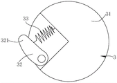
FIG. 9 is a schematic view of the positioning structure;
FIG. 10 is a schematic view of the pawl of FIG. 9 in an outwardly rotated condition;
fig. 11 is another structural schematic diagram of the scraper.
Detailed Description
The present invention will be described in further detail with reference to the following embodiments.
Example 1:
as shown in fig. 1 to 10, it is the 1 st preferred embodiment of the present invention. The cleaning system of this embodiment includes a cleaning machine and a base station. As shown in fig. 8, the cleaning machine is a sweeper 5, the sweeper 5 includes a housing 51 and two mops 52 rotatably disposed at the bottom of the housing 51, and the two mops 52 of the sweeper 5 of the present embodiment are circular and are spaced apart from each other in the left-right direction.
As shown in fig. 1 to 6, the base station of the present embodiment includes a base 1, a scraper 2, and a positioning structure. The base 1 is provided with an accommodating chamber 10 with an opening at the front side for the cleaner to enter, the bottom wall of the accommodating chamber 10 is provided with a groove 101 which is recessed downwards, the cross section of the groove 101 is circular, each mop 52 corresponds to one groove 101, and the number of the grooves 101 is two, and the grooves are arranged at intervals along the left-right direction. With the sweeper 5 in the receiving compartment 10, the mop 52 is located in the corresponding recess 101.
As shown in fig. 2 and 3, there is one scraper 2 corresponding to each groove 101, and the structural form of each groove and scraper is the same, and a set of grooves and scrapers will be described as an example below. The scraping part 2 is rotatably arranged in the groove 101, is a flexible strip-shaped scraping strip as a whole and is arranged along the radial direction of the groove 101, and the mop cloth 52 is contacted with the top of the scraping part 2 under the condition that the sweeper 5 is positioned in the accommodating cavity 10, so that the mop cloth 52 is scraped by the top of the scraping part 2 under the condition that the scraping part 2 and the mop cloth 52 are in relative motion.
As shown in fig. 4 and 7, the bottom of the scraper 2 has a cleaning member for cleaning the bottom wall of the housing chamber 10, the bottom of the cleaning member being in contact with the bottom wall of the recess 101. The cleaning member in this embodiment is a plurality of vertically extending flexible brush posts 22, and the flexible brush posts 22 are arranged at intervals along the length direction of the scraper 2. In this embodiment, the wiper 2 is provided with flexible brush posts 22 at both ends. In addition, the scraping member 2 has a flow channel 20 inside, and the top of the scraping member 2 is provided with a plurality of water outlets 201 communicated with the flow channel 20, and the water outlets 201 are arranged at intervals along the length direction of the scraping member 2. In order to supply water to the flow passage 20, the base 1 has a purified water pipe 4 communicated with the flow passage 20, an outlet of the purified water pipe 4 is communicated with the flow passage 20, and the purified water pipe 4 is communicated with tap water through an electromagnetic valve 6.
As shown in fig. 2 and fig. 3, a drain outlet 102 is formed in the bottom wall of the accommodating chamber 10, and the drain outlet 102 is located between the two grooves 101, located in a space enclosed by the rear wall plate of the accommodating chamber 10 and the two grooves 101, and communicated with the grooves 101. In order to sweep the waste in the groove into the waste discharge opening 102 in time, the waste discharge opening 102 is located on the rotation path of the cleaning member, specifically, the rotation paths of the flexible brush columns at both ends of the scraper 2. Furthermore, it may be located in the path of rotation of the scraper 2.
As shown in fig. 5, 6, 9 and 10, a positioning structure 3 is provided between the scraper 2 and the bottom wall of the base 1 to enable the scraper 2 to rotate in one direction relative to the base 1. Specifically, the positioning structure 3 includes a connecting member 31, a pawl 32 and an elastic member, the connecting member 31 is fixedly mounted on the bottom wall of the base 1, and the pawl 32 enables the scraper 2 to rotate in one direction relative to the connecting member 31. The scraper 2 is mounted on the bottom wall of the accommodating chamber 10 at a position adjacent to the middle by a vertically arranged mounting shaft 11, and a water passage 111 communicated with the flow passage 20 is formed inside the mounting shaft 11. The bottom of the scraper 2 has a mounting groove 24 with an opening facing downwards for accommodating the connecting piece 31, and the connecting piece 31 has a water passage 311 communicating the water passage 111 and the flow passage 20. An accommodating groove 241 for accommodating the pawl 32 is formed between the inner side wall of the mounting groove 24 and the connecting member 31, a tooth groove 242 is formed on the inner side wall of the mounting groove 24 at a position corresponding to the accommodating groove 241, the pawl 32 is rotatably disposed on the connecting member 31, the free end of the pawl 32 has a protrusion 321 engaged with the tooth groove 242, and the elastic member acts on the pawl 32 and tends to keep the pawl 32 engaged with the tooth groove 242. The elastic member is a spring 33, one end of the spring 33 is connected to the connecting member 31, and the other end of the spring 33 is connected to the pawl 32. Thus, as shown in fig. 5 and 6, when the scraper 2 rotates to a state where the tooth groove 242 thereof is engaged with the protrusion 321 of the pawl 32, the connecting member is fixed relative to the scraper 2; when the tooth space 242 of the scraper 2 is in a non-engagement state with the projection 321 of the pawl 32 during rotation, the scraper 2 rotates relative to the connecting member.
The working process of the cleaning system is as follows:
when the sweeper 5 enters the accommodating cavity 10 of the base station to clean the mop 52 or wet the mop 52, as shown in fig. 2 and 6, the mop 52 of the sweeper 5 can rotate to drive the scraper 2 to rotate, at this time, the scraper 2 and the connecting piece are relatively fixed, in the process of continuing rotating the mop 52, the top of the scraper 2 is scraped, so that the mop 52 is cleaned, when water needs to be added, tap water enters the flow channel 20 inside the scraper 2 through the water purifying pipe 4, the water outlet channel 111 and the water outlet channel 311 by controlling the opening and closing of the electromagnetic valve 6 and is sprayed out from the water outlet 201 of the scraper 2, specifically referring to the direction indicated by the arrow in fig. 4, so as to achieve the function of cleaning and wetting the mop 52.
After the sweeper 5 finishes sweeping, the sweeper enters the accommodating cavity 10 of the base station, as shown in fig. 3 and 5, the mop 52 of the sweeper 5 is controlled to rotate in the same direction as the scraper 2, the mop 52 also drives the scraper 2 to rotate while rotating, the cleaning part at the lower part of the scraper 2 scrapes the bottom wall of the groove 101, dirt is gathered near the sewage discharge outlet 102, meanwhile, tap water enters the flow channel 20 inside the scraper 2 through the water purifying pipe 4, the water outlet 111 and the water passing channel 311 by controlling the opening and closing of the electromagnetic valve 6 and is sprayed out from the water outlet 201 of the scraper 2, the dirt can be flushed into the sewage discharge outlet 102, and the sewage discharge outlet 102 is connected with a sewer so as to achieve the self-cleaning function of the bottom wall of the accommodating cavity 10.
Example 2:
fig. 11 shows a 2 nd preferred embodiment of the present invention. This embodiment differs from the above embodiment 1 only in that: the cleaning elements are different in structural form, and specifically, the cleaning elements are vertically arranged flexible scrapers 21, and the flexible scrapers 21 extend along the length direction of the scrapers 2.
Claims (17)
1. A base station for a cleaning machine, comprising:
a base (1) which is internally provided with an accommodating chamber (10) with an opening at the front side for the cleaner to enter;
a scraper (2) located inside the housing chamber (10), arranged on the bottom wall of the housing chamber (10) and arranged to rotate with respect to the base (1);
the method is characterized in that: the bottom of the scraper (2) is provided with a cleaning piece for cleaning the bottom wall of the accommodating chamber (10).
2. The base station of claim 1, wherein: the scraping piece (2) is a flexible scraping strip which is integrally in a strip shape, the cleaning piece is a flexible scraping plate (21) which is vertically arranged, and the flexible scraping plate (21) extends along the length direction of the scraping piece (2).
3. The base station of claim 1, wherein: scrape piece (2) and be banding flexibility for whole and scrape the strip, the clearance piece is vertical extension's flexible brush post (22), flexible brush post (22) have a plurality ofly, and along the length direction interval arrangement of scraping piece (2).
4. The base station of claim 1, wherein: the bottom wall of the accommodating chamber (10) is provided with a groove (101) which is sunken downwards, the scraper (2) can be rotatably arranged in the groove (101), and the bottom of the cleaning piece is in contact with the bottom wall of the groove (101).
5. The base station of claim 4, wherein: the cross section of the groove (101) is circular, so that the mop cloth (52) of the cleaning machine can be accommodated in the groove.
6. The base station of claim 1, wherein: a sewage draining outlet (102) is formed in the bottom wall of the accommodating chamber (10), and the sewage draining outlet (102) is located on the rotating path of the cleaning piece or the scraping piece (2).
7. The base station of claim 6, wherein: the two scraping pieces (2) are arranged at intervals along the left-right direction.
8. The base station of claim 7, wherein: the bottom wall of the accommodating chamber (10) is provided with a groove (101) which is sunken downwards, each scraper (2) corresponds to one groove (101), the scrapers (2) can be rotatably arranged in the grooves (101), and the sewage discharge port (102) is positioned between the two grooves (101) and communicated with the grooves (101).
9. The base station of claim 8, wherein: the sewage draining outlet (102) is positioned in a space enclosed by the rear wall plate of the accommodating chamber (10) and the two grooves (101).
10. The base station of claim 1, wherein: and a positioning structure (3) which can enable the scraping piece (2) to rotate relative to the base (1) in one direction is arranged between the scraping piece (2) and the bottom wall of the base (1).
11. The base station of claim 10, wherein: the positioning structure (3) comprises a connecting piece (31) fixedly mounted on the bottom wall of the base (1), an elastic piece and a pawl (32) capable of enabling the scraper (2) to rotate in a single direction relative to the connecting piece (31), the bottom of the scraper (2) is provided with a mounting groove (24) with an opening facing downwards to accommodate the connecting piece (31), an accommodating groove (241) for accommodating the pawl (32) is formed between the inner side wall of the mounting groove (24) and the connecting piece (31), the inner side wall of the mounting groove (24) is provided with a tooth groove (242) at a position corresponding to the accommodating groove (241), the pawl (32) is rotatably arranged on the connecting piece (31), the free end of the pawl (32) is provided with a convex part (321) meshed with the tooth groove (242), and the elastic piece acts on the pawl (32) and enables the pawl (32) to keep a tendency of being meshed with the tooth groove (242).
12. The base station according to any of claims 1 to 11, characterized by: the scraping piece (2) is internally provided with a flow channel (20), and the top of the scraping piece (2) is provided with a water outlet (201) communicated with the flow channel (20).
13. The base station of claim 12, wherein: the base (1) is provided with a water purifying pipe (4) communicated with the flow channel (20), and a water outlet of the water purifying pipe (4) is communicated with the flow channel (20).
14. The base station of claim 12, wherein: the scraper (2) is installed on the bottom wall of the accommodating chamber (10) through a vertically arranged installation shaft (11), and a water flowing channel (111) communicated with the flow channel (20) is formed in the installation shaft (11).
15. The base station of claim 12, wherein: scrape piece (2) and be the banding flexible strip of scraping for whole, apopore (201) have a plurality ofly, and along the length direction interval arrangement of scraping piece (2).
16. A cleaning system having the base station of any one of claims 1 to 15, characterized by: the cleaning machine comprises a machine shell (51) and a mop cloth (52) which is rotatably arranged at the bottom of the machine shell (51), wherein the mop cloth (52) is contacted with the top of the scraping piece (2) under the state that the cleaning machine is positioned in the accommodating chamber (10).
17. The cleaning system of claim 16, wherein: the cleaning machine is a sweeper (5).
Priority Applications (1)
| Application Number | Priority Date | Filing Date | Title |
|---|---|---|---|
| CN202221591078.1U CN218074846U (en) | 2022-06-23 | 2022-06-23 | Base station for cleaning machine and cleaning system |
Applications Claiming Priority (1)
| Application Number | Priority Date | Filing Date | Title |
|---|---|---|---|
| CN202221591078.1U CN218074846U (en) | 2022-06-23 | 2022-06-23 | Base station for cleaning machine and cleaning system |
Publications (1)
| Publication Number | Publication Date |
|---|---|
| CN218074846U true CN218074846U (en) | 2022-12-20 |
Family
ID=84477095
Family Applications (1)
| Application Number | Title | Priority Date | Filing Date |
|---|---|---|---|
| CN202221591078.1U Active CN218074846U (en) | 2022-06-23 | 2022-06-23 | Base station for cleaning machine and cleaning system |
Country Status (1)
| Country | Link |
|---|---|
| CN (1) | CN218074846U (en) |
-
2022
- 2022-06-23 CN CN202221591078.1U patent/CN218074846U/en active Active
Similar Documents
| Publication | Publication Date | Title |
|---|---|---|
| CN210228029U (en) | Ground cleaning equipment | |
| CN205094314U (en) | Window cleaner | |
| CN211862713U (en) | Base station and cleaning robot system | |
| CN209808234U (en) | Cleaning seat for cleaning wiping cloth in mopping robot | |
| CN215227298U (en) | Cleaning base station and cleaning device | |
| CN114680747B (en) | Cleaning head and cleaning tool | |
| CN111728543A (en) | Multifunctional cleaning device and cleaning machine | |
| CN218074846U (en) | Base station for cleaning machine and cleaning system | |
| CN216702471U (en) | Base station and floor washing machine | |
| CN216020859U (en) | Cleaning head and cleaning tool | |
| CN214718787U (en) | Cleaning device and base station | |
| JP5697653B2 (en) | Sponge mop squeezer | |
| CN217310124U (en) | Water channel system of floor washing machine and floor washing machine | |
| CN217365701U (en) | Surface cleaning machine simple and convenient in structure | |
| CN216020820U (en) | Surface cleaning device with good wiping effect | |
| CN216020839U (en) | Surface cleaning device capable of preventing sewage from overflowing | |
| CN216020837U (en) | Surface cleaning device with good use experience | |
| CN217907637U (en) | Cleaning device and cleaning system | |
| CN217938119U (en) | Convenient to use's surface cleaning device | |
| CN216020819U (en) | Surface cleaning device with good liquid supply effect | |
| CN218186663U (en) | Convenient to use's surface cleaning system | |
| CN216026490U (en) | Cleaning system with good use experience | |
| CN217013854U (en) | Cleaning robot and automatic cleaning cloth cleaning structure thereof | |
| CN219846454U (en) | Cleaning machine | |
| CN216907819U (en) | Mop self-cleaning system and cleaning equipment |
Legal Events
| Date | Code | Title | Description |
|---|---|---|---|
| GR01 | Patent grant | ||
| GR01 | Patent grant |