CN218025385U - Filling device is used in paint produce with adjustable - Google Patents
Filling device is used in paint produce with adjustable Download PDFInfo
- Publication number
- CN218025385U CN218025385U CN202221407358.2U CN202221407358U CN218025385U CN 218025385 U CN218025385 U CN 218025385U CN 202221407358 U CN202221407358 U CN 202221407358U CN 218025385 U CN218025385 U CN 218025385U
- Authority
- CN
- China
- Prior art keywords
- fixedly connected
- push rod
- baffle
- filling device
- adjusting
- Prior art date
- Legal status (The legal status is an assumption and is not a legal conclusion. Google has not performed a legal analysis and makes no representation as to the accuracy of the status listed.)
- Active
Links
Images

Landscapes
- Coating Apparatus (AREA)
Abstract
The utility model discloses the coating production field, specific filling device is used in coating production with adjustable says so, including bottom plate and adjustment mechanism, the top of bottom plate is provided with adjustment mechanism, adjustment mechanism includes base, electric lift push rod, baffle, slide rail, pulley, driving frame, splint, protection pad and electric telescopic rod, the equal fixedly connected with electric lift push rod in top of base, electric lift push rod's other end fixedly connected with baffle, the slide rail has been seted up to the inboard of baffle, and in operation, at first place the collecting vessel the top of baffle and start both sides electric lift push rod afterwards and promote the driving frame and make it slide on the slide rail through the pulley to it carries out a fixed centre gripping to the collecting vessel to drive both sides splint, provides effectual guarantee for the stability of canning, can start electric lift push rod simultaneously and carry out a lift adjustment's purpose to the baffle, so that carry out a lift adjustment to suitable position to the collecting vessel.
Description
Technical Field
The utility model relates to a coating production field specifically is a filling device for coating production with adjustable.
Background
The outdoor cabinet is a cabinet body which is directly under the influence of natural climate, is made of metal or nonmetal materials, does not allow an unauthorized operator to enter the cabinet body for operation, and provides an outdoor physical working environment and a safety system for a wireless communication station or a wired network station workstation.
The filling device for paint production, as disclosed in chinese patent CN210710698U, comprises a bottom plate, two supporting legs are fixedly mounted on both sides of the bottom plate, and two supporting columns are fixedly mounted on the top of the bottom plate. This filling device for coating production, through setting up the slider, when coating is carrying out the filling, the servo motor of device both sides starts, make the screw rod rotatory, drive transmission pipe and stopper and stretch out to the centre, clip the bucket of dress coating, treat that it finishes after the filling, can continue the antedisplacement, at this moment, electronic slide rail is controlled the stopper and is followed it and move, stabilize it on the conveyer belt, even the conveyer belt takes place to stop also can't make its removal, when the bucket of dress coating removes to the workman of being on the production line and takies away, servo motor reverses, withdraw the stopper, electronic slide rail makes the slider return the filling operation of waiting for next time simultaneously, the stable effect of conveying has been reached.
But the filling device for the coating production who uses at present mostly adjusts the effect not good, in the use, can not be effectual to the fixed condition that leads to the collecting vessel to collapse easily of collecting vessel of different sizes to irrigation efficiency's problem has been influenced.
Therefore, the filling device for the adjustable paint production is provided for solving the problems.
SUMMERY OF THE UTILITY MODEL
In order to compensate prior art's not enough, solved the not good problem of the most regulation effect of filling device for the coating production who uses at present, the utility model provides a filling device for coating production with adjustable.
The utility model provides a technical scheme that its technical problem adopted is: a filling device is used in paint produce with adjustable, including bottom plate and adjustment mechanism, the top of bottom plate is provided with adjustment mechanism, adjustment mechanism includes base, electric lift push rod, baffle, slide rail, pulley, driving frame, splint, protection pad and electric telescopic rod, the equal fixedly connected with electric lift push rod in top of base, the other end fixedly connected with baffle of electric lift push rod, the slide rail has been seted up to the inboard of baffle, the equal swing joint in inside both sides of slide rail has the pulley, one side fixedly connected with driving frame of pulley, the opposite side fixedly connected with splint of driving frame, a side surface of splint is provided with the protection pad, one side fixedly connected with electric telescopic rod of driving frame.
The bottom plate is characterized in that both sides below the bottom plate are fixedly connected with thread adjusting sleeves, the inner sides of the thread adjusting sleeves are movably connected with thread adjusting rods, and the lower ends of the thread adjusting rods are fixedly connected with adjusting seats.
Preferably, the top of bottom plate is provided with automatic defeated material mechanism, and automatic defeated material mechanism includes pump box, water pump, inlet pipe, discharging pipe, storage case, play feed cylinder and support frame, and the inboard fixedly connected with water pump of pump box, and the feed inlet fixedly connected with inlet pipe of water pump, and the discharge gate fixedly connected with discharging pipe of water pump.
Preferably, the other end of the discharge pipe is fixedly connected with a storage box, a discharge barrel is fixedly connected to the lower portion of the storage box, and a support frame is welded around the outer side of the storage box.
Preferably, the inner side of the material storage box is provided with a quantifying mechanism, the quantifying mechanism comprises a viewing window and a scale sticker, the scale sticker is fixedly connected to the inner side of the viewing window, and the viewing window and the material storage box are of a penetrating structure.
Preferably, the baffle, the electric lifting push rod and the base form a lifting structure, and the base is connected with the bottom plate in a welding manner.
Preferably, the clamping plates, the pulleys and the sliding rails form a sliding structure, and the number of the clamping plates is two.
Preferably, the protection pad is in adhesive connection with the clamping plate, and the electric telescopic push rod is in welded connection with the baffle.
Preferably, the adjusting seat is in threaded connection with the threaded adjusting sleeve through a threaded adjusting rod, and the threaded adjusting rod and the adjusting seat are vertically distributed.
The utility model discloses an useful part lies in:
1. the utility model discloses an adjustment mechanism, a pedestal, electric lift push rod, the baffle, a slide rail, the pulley, the gear frame, splint, the setting of protection pad and electric telescopic push rod, can carry out a function of adjusting to this irrigation equipment, solved in the use, can not effectually lead to the fixed condition that leads to the collecting vessel to collapse easily to the collecting vessel of not unidimensional size, thereby the problem of irrigation efficiency has been influenced, in operation, at first place the collecting vessel the top of baffle and start both sides electric lift push rod to promote the gear frame afterwards and make it slide on the slide rail through the pulley, so that drive both sides splint and carry out a fixed centre gripping to the collecting vessel, stability for the canning provides effectual guarantee, can start electric lift push rod to carry out a lift adjustment's purpose to the baffle simultaneously, so that carry out a lift adjustment to suitable position to the collecting vessel.
Drawings
In order to more clearly illustrate the embodiments of the present invention or the technical solutions in the prior art, the drawings needed to be used in the description of the embodiments or the prior art will be briefly described below, it is obvious that the drawings in the following description are only some embodiments of the present invention, and for those skilled in the art, other drawings can be obtained according to the drawings without inventive exercise.
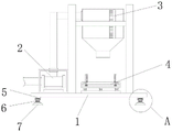
Fig. 1 is a front view of a filling device for producing an adjustable paint according to an embodiment;
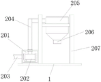
FIG. 2 is a front view of an automatic feed mechanism according to an embodiment;
FIG. 3 is a front view of an embodiment adjustment mechanism;
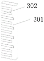
FIG. 4 is a perspective view of a dosing mechanism according to an embodiment;
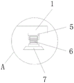
fig. 5 is an enlarged view of a point a in fig. 1.
In the figure: 1. a base plate; 2. an automatic material conveying mechanism; 201. a pump box; 202. a water pump; 203. a feeding pipe; 204. a discharge pipe; 205. a material storage box; 206. a discharging barrel; 207. a support frame; 3. a dosing mechanism; 301. a viewing window; 302. a scale is pasted; 4. an adjustment mechanism; 401. a base; 402. an electric lifting push rod; 403. a baffle plate; 404. a slide rail; 405. a pulley; 406. a transmission frame; 407. a splint; 408. a protective pad; 409. an electric telescopic push rod; 5. a thread adjusting sleeve; 6. a threaded adjusting rod; 7. an adjusting seat.
Detailed Description
The technical solutions in the embodiments of the present invention will be described clearly and completely with reference to the accompanying drawings in the embodiments of the present invention, and it is obvious that the described embodiments are only some embodiments of the present invention, not all embodiments. Based on the embodiments in the present invention, all other embodiments obtained by a person skilled in the art without creative efforts belong to the protection scope of the present invention.
Referring to fig. 1-5, an adjustable filling device for paint production includes a bottom plate 1 and an adjusting mechanism 4, and is characterized in that: the top of bottom plate 1 is provided with adjustment mechanism 4, adjustment mechanism 4 includes base 401, electric lift push rod 402, baffle 403, slide rail 404, pulley 405, driving frame 406, splint 407, protection pad 408 and electric telescopic rod 409, the equal fixedly connected with electric lift push rod 402 in top of base 401, the other end fixedly connected with baffle 403 of electric lift push rod 402, slide rail 404 has been seted up to the inboard of baffle 403, the equal swing joint in inside both sides of slide rail 404 has pulley 405, one side fixedly connected with driving frame 406 of pulley 405, the opposite side fixedly connected with splint 407 of driving frame 406, a side surface of splint 407 is provided with protection pad 408, one side fixedly connected with electric telescopic rod 409 of driving frame 406.
The equal fixedly connected with screw thread adjusting collar 5 in the below both sides of bottom plate 1, the inboard swing joint of screw thread adjusting collar 5 has screw thread adjusting rod 6, and the lower extreme fixedly connected with of screw thread adjusting rod 6 adjusts seat 7.
This embodiment, bottom plate 1's top is provided with automatic defeated material mechanism 2, and automatic defeated material mechanism 2 includes pump box 201, water pump 202, inlet pipe 203, discharging pipe 204, storage case 205, go out feed cylinder 206 and support frame 207, and the inboard fixedly connected with water pump 202 of pump box 201, and water pump 202's feed inlet fixedly connected with inlet pipe 203, and water pump 202's discharge gate fixedly connected with discharging pipe 204, in the use, can start water pump 202 and go into storage case 205 through the manual coating of inlet pipe 203 and carry out the purpose of discharging through going out feed cylinder 206, the purpose of automatic filling has been promoted, the labor intensity has been saved, irrigation efficiency has been promoted.
This embodiment, the other end fixedly connected with storage tank 205 of discharging pipe 204, and the below fixedly connected with play feed cylinder 206 of storage tank 205, and welded connection has support frame 207 around the outside of storage tank 205, in the use, because storage tank 205 is welded connection with support frame 207 to stability for storage tank 205 provides effectual guarantee.
In this embodiment, the inboard of storage case 205 is provided with dosing mechanism 3, and dosing mechanism 3 is including viewing window 301 and scale subsides 302, and the inboard fixedly connected with scale subsides 302 of viewing window 301, and viewing window 301 and storage case 205 are for running through the structure, and in the use, can watch the inside quantitative condition of storage case 205 through the scale subsides 302 on viewing window 301 to in the purpose of carrying out a reasonable irrigation.
In this embodiment, baffle 403, electric lift push rod 402 and base 401 constitute elevation structure, and base 401 and bottom plate 1 are welded connection, in the use, can start electric lift push rod 402 and drive baffle 403 lift adjustment to suitable height to carry out a lift adjustment's purpose to the surge drum on the baffle 403.
In this embodiment, splint 407, pulley 405 and slide rail 404 constitute sliding construction, and splint 407's quantity is two, and in the use, can start both sides electric lift push rod 402 and promote driving frame 406 and make it slide on slide rail 404 through pulley 405 to drive both sides splint 407 and carry out a fixed centre gripping to the collecting vessel, provide effectual guarantee for the stability of canning.
In this embodiment, the protection pad 408 and the clamping plate 407 are connected by adhesive, and the electric telescopic rod 409 and the baffle 403 are connected by welding, so that in the using process, the surface of the clamping plate 407 is provided with the protection pad 408, and the purpose of protecting the clamped collecting cylinder can be achieved.
In the embodiment, the adjusting base 7 is in threaded connection with the threaded adjusting sleeve 5 through the threaded adjusting rod 6, the threaded adjusting rod 6 and the adjusting base 7 are vertically distributed, and in the using process, the threaded adjusting rod 6 can be screwed to achieve the purpose of lifting adjustment of the adjusting base 7 through the threaded adjusting sleeve 5, so that the filling device can be stably placed.
When the adjustable paint filling device is used, firstly, the filling device is moved to a proper position, then the threaded adjusting rod 6 is screwed to perform a lifting adjustment on the adjusting seat 7 through the threaded adjusting sleeve 5, the filling device is stably placed, then an external power supply is connected, one end of the feeding pipe 203 is connected with the paint side, when the filling is needed, the collecting cylinder is placed above the baffle 403, then the electric lifting push rods 402 on two sides are started to push the transmission frame 406 to slide on the sliding rail 404 through the pulley 405 so as to drive the clamping plates 407 on two sides to fixedly clamp the collecting cylinder, then the electric lifting push rods 402 are started to drive the collecting cylinder to be adjusted to a proper height through the baffle 403 according to the needed requirement, then the water pump 202 is started to manually discharge paint into the storage box 205 through the discharging pipe 204 through the feeding pipe 203 and discharge the discharging pipe 206 so as to discharge the paint, and the working principle of the adjustable paint filling device for paint production is achieved.
In the description herein, references to the description of "one embodiment," "an example," "a specific example," etc., mean that a particular feature, structure, material, or characteristic described in connection with the embodiment or example is included in at least one embodiment or example of the invention. In this specification, the schematic representations of the terms used above do not necessarily refer to the same embodiment or example. Furthermore, the particular features, structures, materials, or characteristics described may be combined in any suitable manner in any one or more embodiments or examples.
The foregoing shows and describes the general principles, essential features, and advantages of the invention. It will be understood by those skilled in the art that the present invention is not limited to the above embodiments, and that the foregoing embodiments and descriptions are provided only to illustrate the principles of the present invention without departing from the spirit and scope of the present invention.
Claims (8)
1. The utility model provides a filling device is used in paint produce with adjustable, includes bottom plate (1) and adjustment mechanism (4), its characterized in that: an adjusting mechanism (4) is arranged above the bottom plate (1), the adjusting mechanism (4) comprises a base (401), an electric lifting push rod (402), a baffle (403), a sliding rail (404), a pulley (405), a transmission frame (406), a clamping plate (407), a protective pad (408) and an electric telescopic push rod (409), the electric lifting push rod (402) is fixedly connected above the base (401), the other end of the electric lifting push rod (402) is fixedly connected with the baffle (403), the sliding rail (404) is arranged on the inner side of the baffle (403), the pulley (405) is movably connected to each of two inner sides of the sliding rail (404), the transmission frame (406) is fixedly connected to one side of the pulley (405), the clamping plate (407) is fixedly connected to the other side of the transmission frame (406), the protective pad (408) is arranged on the surface of one side of the clamping plate (407), and the electric telescopic push rod (409) is fixedly connected to one side of the transmission frame (406);
the thread adjusting device is characterized in that thread adjusting sleeves (5) are fixedly connected to two sides of the lower portion of the bottom plate (1), thread adjusting rods (6) are movably connected to the inner sides of the thread adjusting sleeves (5), and adjusting seats (7) are fixedly connected to the lower ends of the thread adjusting rods (6).
2. The filling device for adjustable paint production as claimed in claim 1, wherein: the top of bottom plate (1) is provided with automatic defeated material mechanism (2), and automatic defeated material mechanism (2) including pump box (201), water pump (202), inlet pipe (203), discharging pipe (204), storage case (205), play feed cylinder (206) and support frame (207), and inboard fixedly connected with water pump (202) of pump box (201), and feed inlet fixedly connected with inlet pipe (203) of water pump (202), and the discharge gate fixedly connected with discharging pipe (204) of water pump (202).
3. The filling device for producing the adjustable paint as claimed in claim 2, wherein: the other end fixedly connected with storage case (205) of discharging pipe (204), and the below fixedly connected with play feed cylinder (206) of storage case (205), and welded connection has support frame (207) around the outside of storage case (205).
4. The filling device for producing the adjustable paint as claimed in claim 3, wherein: the inner side of the storage box (205) is provided with a quantifying mechanism (3), the quantifying mechanism (3) comprises a viewing window (301) and a scale sticker (302), the scale sticker (302) is fixedly connected to the inner side of the viewing window (301), and the viewing window (301) and the storage box (205) are of a penetrating structure.
5. The filling device for producing the adjustable paint as claimed in claim 1, wherein: the baffle (403), the electric lifting push rod (402) and the base (401) form a lifting structure, and the base (401) is connected with the bottom plate (1) in a welding mode.
6. The filling device for adjustable paint production as claimed in claim 1, wherein: the clamping plates (407), the pulleys (405) and the sliding rails (404) form a sliding structure, and the number of the clamping plates (407) is two.
7. The filling device for producing the adjustable paint as claimed in claim 1, wherein: the protective pad (408) is in adhesive connection with the clamping plate (407), and the electric telescopic push rod (409) is in welded connection with the baffle (403).
8. The filling device for producing the adjustable paint as claimed in claim 1, wherein: the adjusting seat (7) is in threaded connection with the threaded adjusting sleeve (5) through the threaded adjusting rod (6), and the threaded adjusting rod (6) and the adjusting seat (7) are vertically distributed.
Priority Applications (1)
| Application Number | Priority Date | Filing Date | Title |
|---|---|---|---|
| CN202221407358.2U CN218025385U (en) | 2022-06-07 | 2022-06-07 | Filling device is used in paint produce with adjustable |
Applications Claiming Priority (1)
| Application Number | Priority Date | Filing Date | Title |
|---|---|---|---|
| CN202221407358.2U CN218025385U (en) | 2022-06-07 | 2022-06-07 | Filling device is used in paint produce with adjustable |
Publications (1)
| Publication Number | Publication Date |
|---|---|
| CN218025385U true CN218025385U (en) | 2022-12-13 |
Family
ID=84374679
Family Applications (1)
| Application Number | Title | Priority Date | Filing Date |
|---|---|---|---|
| CN202221407358.2U Active CN218025385U (en) | 2022-06-07 | 2022-06-07 | Filling device is used in paint produce with adjustable |
Country Status (1)
| Country | Link |
|---|---|
| CN (1) | CN218025385U (en) |
-
2022
- 2022-06-07 CN CN202221407358.2U patent/CN218025385U/en active Active
Similar Documents
| Publication | Publication Date | Title |
|---|---|---|
| CN105149758B (en) | A kind of self routing welder | |
| CN211841699U (en) | Fixing device for automobile part detection | |
| CN218025385U (en) | Filling device is used in paint produce with adjustable | |
| CN114453815A (en) | Welding operation table with welding position capable of being adjusted in real time for machining mechanical die parts | |
| CN207311515U (en) | Mobile lifting turning trolley | |
| CN205836005U (en) | PE sealing of tube lifting type tool | |
| CN209424796U (en) | A kind of double-station heat exchanger tube sheet automatically welding workstation | |
| CN206764180U (en) | A kind of showcase hanger rapid processing equipment | |
| CN207139132U (en) | A kind of showcase produces welder with peg | |
| CN211325819U (en) | Animal doctor uses four limbs location platform | |
| CN208895429U (en) | A kind of small-bore pipe automatic welding machine for butt joint | |
| CN213888912U (en) | Device for preventing irregular body welding deformation of multiaspect | |
| CN114619113A (en) | Brazing equipment and method for upper cover of compressor | |
| CN210235459U (en) | Filling head moving device for filling machine | |
| CN204415753U (en) | A kind of dropout ton chartered plane automatically | |
| CN208361083U (en) | A kind of adjustable multi-position cillin bottle feed bin | |
| CN209349795U (en) | A kind of pipe butt welding skill training group is to device | |
| CN205869830U (en) | Automobile part tool fixture | |
| CN209259082U (en) | A kind of general extraction device in feeding system | |
| CN111215564A (en) | Automatic welding machine for electric power anchor rod | |
| CN219259127U (en) | Rubber band machine material feeding unit | |
| CN108856959A (en) | A kind of automatic assembly line pallet jacking positioning mechanism of television set | |
| CN216549581U (en) | High-pressure filling equipment with adjust locate function | |
| CN219986402U (en) | Cutting device is used in production of net piece clamp | |
| CN216764828U (en) | Ultrasonic extraction device of plant essential oil |
Legal Events
| Date | Code | Title | Description |
|---|---|---|---|
| GR01 | Patent grant | ||
| GR01 | Patent grant |