CN114453815A - Welding operation table with welding position capable of being adjusted in real time for machining mechanical die parts - Google Patents
Welding operation table with welding position capable of being adjusted in real time for machining mechanical die parts Download PDFInfo
- Publication number
- CN114453815A CN114453815A CN202210197891.9A CN202210197891A CN114453815A CN 114453815 A CN114453815 A CN 114453815A CN 202210197891 A CN202210197891 A CN 202210197891A CN 114453815 A CN114453815 A CN 114453815A
- Authority
- CN
- China
- Prior art keywords
- drive
- welding
- rotate
- rod
- rotates
- Prior art date
- Legal status (The legal status is an assumption and is not a legal conclusion. Google has not performed a legal analysis and makes no representation as to the accuracy of the status listed.)
- Pending
Links
Images


Classifications
-
- B—PERFORMING OPERATIONS; TRANSPORTING
- B23—MACHINE TOOLS; METAL-WORKING NOT OTHERWISE PROVIDED FOR
- B23K—SOLDERING OR UNSOLDERING; WELDING; CLADDING OR PLATING BY SOLDERING OR WELDING; CUTTING BY APPLYING HEAT LOCALLY, e.g. FLAME CUTTING; WORKING BY LASER BEAM
- B23K37/00—Auxiliary devices or processes, not specially adapted to a procedure covered by only one of the preceding main groups
- B23K37/04—Auxiliary devices or processes, not specially adapted to a procedure covered by only one of the preceding main groups for holding or positioning work
- B23K37/0461—Welding tables
-
- B—PERFORMING OPERATIONS; TRANSPORTING
- B23—MACHINE TOOLS; METAL-WORKING NOT OTHERWISE PROVIDED FOR
- B23K—SOLDERING OR UNSOLDERING; WELDING; CLADDING OR PLATING BY SOLDERING OR WELDING; CUTTING BY APPLYING HEAT LOCALLY, e.g. FLAME CUTTING; WORKING BY LASER BEAM
- B23K37/00—Auxiliary devices or processes, not specially adapted to a procedure covered by only one of the preceding main groups
- B23K37/04—Auxiliary devices or processes, not specially adapted to a procedure covered by only one of the preceding main groups for holding or positioning work
- B23K37/0426—Fixtures for other work
- B23K37/0435—Clamps
- B23K37/0443—Jigs
-
- B—PERFORMING OPERATIONS; TRANSPORTING
- B23—MACHINE TOOLS; METAL-WORKING NOT OTHERWISE PROVIDED FOR
- B23K—SOLDERING OR UNSOLDERING; WELDING; CLADDING OR PLATING BY SOLDERING OR WELDING; CUTTING BY APPLYING HEAT LOCALLY, e.g. FLAME CUTTING; WORKING BY LASER BEAM
- B23K37/00—Auxiliary devices or processes, not specially adapted to a procedure covered by only one of the preceding main groups
- B23K37/04—Auxiliary devices or processes, not specially adapted to a procedure covered by only one of the preceding main groups for holding or positioning work
- B23K37/047—Auxiliary devices or processes, not specially adapted to a procedure covered by only one of the preceding main groups for holding or positioning work moving work to adjust its position between soldering, welding or cutting steps
-
- B—PERFORMING OPERATIONS; TRANSPORTING
- B23—MACHINE TOOLS; METAL-WORKING NOT OTHERWISE PROVIDED FOR
- B23K—SOLDERING OR UNSOLDERING; WELDING; CLADDING OR PLATING BY SOLDERING OR WELDING; CUTTING BY APPLYING HEAT LOCALLY, e.g. FLAME CUTTING; WORKING BY LASER BEAM
- B23K37/00—Auxiliary devices or processes, not specially adapted to a procedure covered by only one of the preceding main groups
- B23K37/08—Auxiliary devices or processes, not specially adapted to a procedure covered by only one of the preceding main groups for flash removal
Abstract
The utility model discloses a welding operation table with welding positions capable of being adjusted in real time for machining mechanical die parts, which comprises a base, wherein two groups of adjusting grooves are formed in the inner side of the base, a transmission rod penetrates through the inner side of the base and penetrates through the two groups of adjusting grooves, two groups of transmission rollers are arranged on the outer side of the transmission rod and are positioned on the inner sides of the adjusting grooves, and a transmission belt is movably arranged on the outer side of each transmission roller. According to the utility model, the movable inner pipe is arranged, the motor is controlled to operate to drive the driving wheel at the output end to rotate, the driving wheel rotates to drive the driving belt at the outer side to rotate, the driving belt rotates to drive the driven wheel at the inner side to rotate, the driven wheel rotates to drive the movable inner pipe at the inner side to rotate at the inner side of the fixed outer ring, the movable inner pipe rotates to drive the adjusting rod and the clamping plate at the inner side to rotate, the clamping plate rotates to drive the tubular workpiece at the inner side to rotate, the device can automatically adjust the welding line angle during welding conveniently, and the workpiece can be comprehensively welded.
Description
Technical Field
The utility model relates to the technical field of machining of mechanical die parts, in particular to a welding operation table with a welding position capable of being adjusted in real time for machining of the mechanical die parts.
Background
Mechanical dies are tools for forming articles, which are composed of various parts, different dies are composed of different parts, and in the process of processing a workpiece, the workpiece needs to be welded, and two individual parts are connected into a whole through welding.
The welding operation table in the prior art has the following defects:
1. patent document CN214239587U discloses a welding operation table, "including a frame, a welding flower basket fixed on the frame; the frame includes frame body, spacing post, cantilever beam subassembly, lead screw, and spacing post is installed on the frame body, the lead screw is installed on the cantilever beam subassembly, the welding basket of flowers includes hand wheel, connecting rod, heating welding spare, guide post, and the hand wheel sets up the lead screw cover, and the hand wheel passes through the lead screw cover with the lead screw and links to each other, and the guide post sets up the sliding sleeve, and the guide post passes through the sliding sleeve with the lead screw and links to each other, and the one end and the lead screw cover of connecting rod are connected, and the other end is connected with the heating welding spare, and the heating welding spare is connected with the guide post. The device is lack of a structure for adjusting the position of a welding workpiece in real time as required during welding, and the position of the workpiece needs to be manually adjusted by workers, so that the device is troublesome.
2. Patent document CN210099162U discloses a multifunctional welding operation table, "comprising a box body, a power adapter, a metal threading hose, a metal hose support, a fan, a lighting device, a magnifier, an electric iron, and a cover body hinged on the box body, wherein an operation panel is arranged in the box body, a mounting cavity is arranged between the box body and the operation panel, a circuit board is arranged in the mounting cavity, and a main power supply interface is arranged on the box body; the main control circuit board is provided with a fuse, a first voltage transformation module and a second voltage transformation module; the operation panel is provided with a welding clamping device, an electric soldering iron placing seat, a first switch, a second switch, a first power supply interface, a second power supply interface, a magnifier mounting port and an electronic rotary voltage regulator, the fan and the lighting device are connected to the second power supply interface through metal threading hoses, and the magnifier is connected to the magnifier mounting port through a metal hose support; the circuit components are connected in a matching mode. This multi-functional welding operation panel in welding process in time the harmful gas of discharge production, and make things convenient for the operator to weld "should be when welding workpiece, owing to lack angle modulation structure, can't weld comprehensively to needs welded place, influence welding quality.
3. Patent document CN205464911U discloses a multifunctional welding operation table, "comprising a base, a first support rod vertically and fixedly arranged on the base, a second support rod connected with the first support rod, a connecting plate fixedly arranged at the end of the second support rod, a connecting rod arranged on the connecting plate, and a clamp arranged at the end of the connecting rod, wherein the clamp is used for fixedly connecting a welding plate; the second supporting rod can rotate around the axis 360 of the first supporting rod, and the clamp can rotate around the axis 360 of the connecting rod. The second supporting rod can move up and down, so that the vertical heights of the connecting plate, the connecting rod and the clamp can be adjusted. The operating table has the advantages of radial adjustment, axial 360-degree adjustment and certain stepless lifting, and is suitable for industrial and mining enterprises, schools and occupational skill training institutions.
4. Patent document CN204148794U discloses a rotary welding operation table, "including a support and a platform, and further including a rotating mechanism, the welding platform is located above the support, and is rotatably connected to the support around the vertical direction through the rotating mechanism. The welding operation table realizes the rotation of the platform relative to the support through the rotating mechanism, and an operator can find any angle suitable for welding without walking, so that the labor intensity is reduced, and the welding work efficiency is improved. In addition, the utility model also discloses a welding tool system which comprises at least one conveyor and at least one rotary welding operation table, wherein the conveyor is arranged along the welding process flow. This conveyer sets up between two welding stations to automatic conveying welding assembly has saved traditional artifical handling process, thereby has further reduced the human cost, has improved simultaneously again and has transported efficiency "the device lacks the structure of collecting the piece, causes the device to clean more troublesome.
Disclosure of Invention
The utility model aims to provide a welding operation table with a welding position for machining mechanical die parts capable of being adjusted in real time, so as to solve the problems in the background technology.
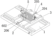
In order to achieve the purpose, the utility model provides the following technical scheme: the welding operation table comprises a base, wherein two groups of adjusting grooves are formed in the inner side of the base, a transmission rod penetrates through the inner side of the base and penetrates through the two groups of adjusting grooves, two groups of transmission rollers are arranged on the outer side of the transmission rod and are positioned on the inner side of the adjusting grooves, a transmission belt is movably arranged on the outer side of each transmission roller, a connecting block is arranged on the upper surface of each transmission belt, and a movable plate is arranged at the top of each connecting block;
the top of the moving plate is provided with support plates, the inner sides of the two groups of support plates are provided with guide slide bars, and the outer sides of the two groups of guide slide bars are sleeved with sliding lantern rings;
the utility model discloses a supporting box, including slip lantern ring, support box, supporting box, two sets of supporting seats are installed to the top bilateral symmetry of support box, fixed outer loop is installed at the top of supporting seat, the bracing piece is installed to the top symmetry of supporting box.
Preferably, two sets of guide slideways are installed at the top of base, and two sets of guide slideways are located between two sets of adjustment tanks, and the motor is installed on the front of base, and the output of motor is connected with the one end of transfer line.
Preferably, the bottom of the movable plate is provided with a guide clamping piece, the bottom of the guide clamping piece is embedded outside the top of the guide slide way, the top of the movable plate is provided with a fixed plate, the fixed plate is positioned between the two groups of supporting plates, a screw rod is movably arranged between the two groups of fixed plates, the front surface of the fixed plate is provided with a servo motor, and the output end of the servo motor is movably connected with the front end of the screw rod.
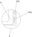
Preferably, an internal thread lantern ring is installed at the bottom of the supporting box, the internal thread lantern ring is sleeved on the outer side of the screw rod through threads, a limiting groove is installed on the inner wall of the supporting box, an intercepting plate is installed at the top of the supporting box in an embedded mode, and a through hole is formed in the inner side of the intercepting plate.
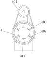
Preferably, the inboard movable mounting of fixed outer loop has movable inner tube, and six sets of ring-type arrangement's regulation pole are installed to the inboard of activity inner tube, and the grip block is installed to the output of six sets of regulation poles, and from the driving wheel is installed in the outside of activity inner tube, and control motor is installed through the connecting piece in the top of fixed outer loop, and control motor's output has the action wheel through connecting rod movable mounting, and the drive belt is installed in the outside of action wheel, and the bottom cover of drive belt is in the outside from the driving wheel.
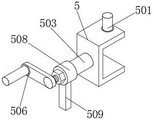
Preferably, solid fixed ring is installed at the top of bracing piece, and the locating part is installed to solid fixed ring's inboard, and the threaded rod is installed to the one end of locating part, and the threaded rod runs through solid fixed ring's one end inner wall, and the fastener is installed to the outside screw thread of threaded rod, and the rocking handle is installed to the one end of threaded rod, and the other end of locating part runs through solid fixed ring's the other end inner wall and installs the bull stick, and the U-shaped cardboard is installed to the one end of bull stick, runs through on the roof of U-shaped cardboard and installs electric telescopic handle, and the antiskid ribbed tile is installed to electric telescopic handle's output.
Preferably, the outer walls of the two sides of the collecting box are provided with supporting clamping pieces which are embedded in the inner side of the limiting groove, and the front surface of the collecting box is provided with a handle.
The working steps of the welding operation platform are as follows:
s1, classifying parts to be welded by workers, placing the two groups of cylindrical workpieces on the inner side of the movable inner tube by the workers when the two groups of cylindrical workpieces need to be welded so that the cylindrical workpieces are located between the groups of clamping plates, meanwhile, parts needing to be welded between the two cylindrical workpieces are abutted together, then controlling the adjusting rod to extend by the workers so that the clamping plates move forwards, and abutting the clamping plates on the outer surfaces of the cylindrical workpieces to fix the two groups of cylindrical workpieces so as to ensure that the workpieces can be welded stably by the device;
s2, after the placement of the workpiece is completed, a worker controls the operation of the motor according to welding requirements, the motor drives the transmission rod at the output end to rotate, the transmission rod rotates to drive the transmission roller at the outer side to rotate, the transmission roller rotates to drive the transmission belt at the outer side to rotate, the transmission belt rotates to drive the connecting block at the top to move, the connecting block moves to drive the moving plate at the top to horizontally displace, the guide clamping piece at the bottom moves along with the moving plate in the moving process, the guide sliding way guides the guide clamping piece to displace, the situation that the moving plate at the top of the guide clamping piece deflects in the moving process is avoided, meanwhile, the servo motor on the fixed plate operates to drive the screw rod at the output end to rotate, the screw rod rotates to drive the thread at the outer side to rotate, the internal thread lantern ring is driven to move through the thread, the internal thread lantern ring moves to drive the support box at the top to displace, and the sliding lantern ring to move, the sliding sleeve ring is sleeved on the outer side of the guide sliding rod, the guide sliding rod is fixed by the supporting plate, the stability of the guide sliding rod is guaranteed, the guide sliding sleeve ring which stably guides the guide sliding rod can be guaranteed to horizontally move back and forth, the situation that the supporting box deviates is avoided, and the supporting box moves to drive a workpiece at the top to adjust the position;
s3, after the workpiece is moved to a designated position, after the top of the workpiece is welded, the motor is controlled to operate to drive the driving wheel at the output end to rotate, the driving wheel rotates to drive the driving belt at the outer side to rotate, the driving belt rotates to drive the driven wheel at the inner side to rotate, the driven wheel rotates to drive the movable inner pipe at the inner side to rotate at the inner side of the fixed outer ring, the movable inner pipe rotates to drive the adjusting rod and the clamping plate at the inner side to rotate, the clamping plate rotates to drive the tubular workpiece at the inner side to rotate, the device can conveniently and automatically adjust the angle of a welding seam during welding, the workpiece is welded in an annular mode, the welding quality is guaranteed, the device is convenient to weld automatically, and the working pressure of workers is reduced;
s4, when a square block-shaped workpiece needs to be welded, a worker places two workpieces needing to be welded on the inner side of a U-shaped clamping plate, two groups of workpieces are abutted together, then an electric telescopic rod extends to drive an anti-slip plate to move forwards, so that the anti-slip plate abuts against the upper surface of the workpiece and clamps the workpiece, when a special-shaped workpiece needs to be welded, the worker can grasp a rocking handle as required to control a threaded rod to rotate, the threaded rod rotates to drive a limiting piece on the inner side of a fixing ring to rotate, the limiting piece rotates to drive a rotating rod to rotate, the rotating rod drives the U-shaped clamping plate to adjust the angle, so that the angle of the workpiece on the inner side is adjusted, and after the workpiece is adjusted to a proper angle, the worker rotates a fastener, so that the fastener and the limiting piece extrude the outer wall of one end of the fixing ring to fix the device and ensure that the workpiece can be normally welded;
s5, a large amount of scraps can appear in the welding process, the scraps fall above the intercepting plate under the influence of gravity, some scraps can pass through the through hole and fall to the inner side of the supporting box, after welding is completed, workers can sweep the scraps on the intercepting plate to the inner side of the through hole, and impurities enter the inner side of the collecting box through the through hole.
Compared with the prior art, the utility model has the beneficial effects that:
1. the utility model is provided with a movable plate and a support box, a motor operates to drive a transmission rod at an output end to rotate, the transmission rod rotates to drive a transmission roller at the outer side to rotate, the transmission roller rotates to drive a transmission belt at the outer side to rotate, the transmission belt rotates to drive a connecting block at the top to move, the connecting block moves at the inner side of an adjusting groove, the connecting block moves to drive the movable plate at the top to horizontally move left and right, a guide clamping piece at the bottom moves along with the movable plate in the moving process, a guide slideway guides the guide clamping piece to move, the moving plate at the top of the guide clamping piece to move in the moving process, a servo motor on a fixed plate operates to drive a screw rod at the output end to rotate, the screw rod rotates to drive a thread at the outer side to rotate, an internal thread lantern ring is driven to move by the thread, the internal thread lantern ring moves to drive the support box at the top to move, and simultaneously drives a sliding lantern ring to move, the slip lantern ring cover is in the outside of guide slide bar, and the guide slide bar is fixed by the backup pad, guarantees the stability of guide slide bar, guarantees that the stable guide slip lantern ring of guide slide bar carries out front and back horizontal migration, avoids supporting the condition that the skew appears in the box, supports the work piece adjusting position that the box removed the drive top, realizes that the work piece position can be adjusted in real time when the welding.
2. According to the utility model, the movable inner tube is installed, the motor is controlled to operate to drive the driving wheel at the output end to rotate, the driving wheel rotates to drive the driving belt at the outer side to rotate, the driving belt rotates to drive the driven wheel at the inner side to rotate, the driven wheel rotates to drive the movable inner tube at the inner side to rotate at the inner side of the fixed outer ring, the movable inner tube rotates to drive the adjusting rod and the clamping plate at the inner side to rotate, and the clamping plate rotates to drive the tubular workpiece at the inner side to rotate.
3. According to the utility model, two workpieces to be welded are placed on the inner side of the U-shaped clamping plate through the installation of the rocking handle, two groups of workpieces are abutted together, then the electric telescopic rod extends to drive the anti-skidding plate to move forwards, so that the anti-skidding plate is abutted to the upper surface of the workpiece to clamp the workpiece, when special-shaped workpieces are required to be welded, a worker can grasp the rocking handle as required to control the rotation of the threaded rod, the rotation of the threaded rod drives the limiting piece on the inner side of the fixing ring to rotate, the limiting piece rotates to drive the rotating rod to rotate, the rotating rod drives the U-shaped clamping plate to adjust the angle, so that the angle of the workpiece on the inner side is driven to be adjusted, after the proper angle is adjusted, the worker rotates the fastening piece to move on the outer side of the threaded rod, so that the fastening piece and the limiting piece extrude the outer wall of one end of the fixing ring, the device is fixed, and the normal welding of the workpieces is ensured.
4. According to the utility model, the collecting box is arranged, a large amount of scraps can be generated in the welding process, the scraps fall above the intercepting plate under the influence of gravity, some scraps can pass through the through hole and fall to the inner side of the supporting box, after welding is completed, workers can sweep the scraps on the intercepting plate to the inner side of the through hole, impurities enter the inner side of the collecting box through the through hole, and after the welding is completed, the workers take out the collecting box for dumping.
Drawings
FIG. 1 is a schematic perspective view of the present invention;
FIG. 2 is a schematic view of a base structure of the present invention;
FIG. 3 is a schematic view of the construction of the collecting box of the present invention;
FIG. 4 is a perspective view of the movable inner tube of the present invention;
FIG. 5 is a schematic view of the movable inner tube structure of the present invention;
FIG. 6 is a schematic view of the structure at position A of the present invention;
FIG. 7 is a schematic perspective view of a U-shaped clamping plate according to the present invention;
FIG. 8 is a schematic view of a U-shaped card of the present invention.
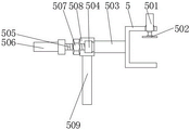
In the figure: 1. a base; 101. an adjustment groove; 102. a transmission rod; 103. a driving roller; 104. an electric motor; 105. a conveyor belt; 106. connecting blocks; 107. a guide chute; 2. moving the plate; 201. guiding the clamping piece; 202. a support plate; 203. a guide slide bar; 204. a fixing plate; 205. a screw rod; 206. a servo motor; 3. a support box; 301. a slip collar; 302. an internal thread collar; 303. a limiting groove; 304. a interception plate; 305. a through hole; 4. a movable inner tube; 401. a supporting seat; 402. fixing the outer ring; 403. a driven wheel; 404. controlling the motor; 405. a driving wheel; 406. a transmission belt; 407. adjusting a rod; 408. a clamping plate; 5. a U-shaped clamping plate; 501. an electric telescopic rod; 502. an anti-skid plate; 503. a rotating rod; 504. a limiting member; 505. a threaded rod; 506. a rocking handle; 507. a fastener; 508. a fixing ring; 509. a support bar; 6. a collection box; 601. supporting the clamping piece; 602. a handle.
Detailed Description
The technical solutions in the embodiments of the present invention will be clearly and completely described below with reference to the drawings in the embodiments of the present invention, and it is obvious that the described embodiments are only a part of the embodiments of the present invention, and not all of the embodiments. All other embodiments, which can be derived by a person skilled in the art from the embodiments given herein without making any creative effort, shall fall within the protection scope of the present invention.
In the description of the present invention, it should be noted that the terms "upper", "lower", "inner", "outer", "front", "rear", "both ends", "one end", "the other end", and the like indicate orientations or positional relationships based on the orientations or positional relationships illustrated in the drawings, and are only for convenience of describing the present invention and simplifying the description, but do not indicate or imply that the referred device or element must have a specific orientation, be configured in a specific orientation, and operate, and thus, should not be construed as limiting the present invention. Furthermore, the terms "first" and "second" are used for descriptive purposes only and are not to be construed as indicating or implying relative importance.
In the description of the present invention, it is to be noted that, unless otherwise explicitly specified or limited, the terms "mounted," "disposed," "connected," and the like are to be construed broadly, such as "connected," which may be fixedly connected, detachably connected, or integrally connected; can be mechanically or electrically connected; they may be connected directly or indirectly through intervening media, or they may be interconnected between two elements. The specific meanings of the above terms in the present invention can be understood in specific cases to those skilled in the art.
Referring to fig. 1-8, an embodiment of the present invention is shown: the welding operation table is used for machining the mechanical die parts and can adjust the welding position in real time;
further, including base 1, two sets of adjustment tank 101 have been seted up to the inboard of base 1, the inboard of base 1 is run through and is installed transfer line 102, and transfer line 102 runs through the inside of two sets of adjustment tank 101, two sets of driving rollers 103 are installed to the outside of transfer line 102, and driving roller 103 is located the inboard of adjustment tank 101, the outside movable mounting of driving roller 103 has transmission band 105, the last surface mounting of transmission band 105 has connecting block 106, two sets of guide slide ways 107 are installed at the top of base 1, and two sets of guide slide ways 107 are located between two sets of adjustment tank 101, and motor 104 is installed in the front of base 1, and the output of motor 104 is connected with the one end of transfer line 102, movable plate 2 is installed at the top of connecting block 106, backup pad 202 is installed at the top of movable plate 2, and guide slide bar 203 is installed to two sets of backup pad 202 inboard, the bottom of the moving plate 2 is provided with a guide clamping piece 201, the bottom of the guide clamping piece 201 is embedded outside the top of the guide slide rail 107, the top of the moving plate 2 is provided with a fixed plate 204, the fixed plate 204 is positioned between two groups of support plates 202, a screw rod 205 is movably arranged between the two groups of fixed plates 204, the front of the fixed plate 204 is provided with a servo motor 206, the output end of the servo motor 206 is movably connected with the front end of the screw rod 205, the outer sides of the two groups of guide slide bars 203 are sleeved with a slide sleeve ring 301, the top of the slide sleeve ring 301 is provided with a support box 3, the bottom of the support box 3 is provided with an internal thread sleeve ring 302, the internal thread sleeve ring 302 is sleeved outside the screw rod 205 through threads, the inner wall of the support box 3 is provided with a limit groove 303, the motor 104 operates to drive the drive rod 102 at the output end to rotate, and the drive rod 102 rotates to drive the drive roller 103 at the outer side to rotate, the transmission roller 103 rotates to drive the transmission belt 105 on the outer side to rotate, the transmission belt 105 rotates to drive the connecting block 106 on the top to move, the connecting block 106 moves on the inner side of the adjusting groove 101, the connecting block 106 moves to drive the moving plate 2 on the top to horizontally move left and right, the guide clamping piece 201 on the bottom moves in the moving process of the moving plate 2, the guide sliding rail 107 guides the guide clamping piece 201 to move, the situation that the moving plate 2 on the top of the guide clamping piece 201 deviates in the moving process is avoided, meanwhile, the servo motor 206 on the fixing plate 204 operates to drive the lead screw 205 on the output end to rotate, the lead screw 205 rotates to drive the thread on the outer side to rotate, the internal thread lantern ring 302 is driven to move through the thread, the internal thread lantern ring 302 moves to drive the support box 3 on the top to move, meanwhile, the sliding lantern ring 301 is driven to move, the sliding lantern ring 301 is sleeved on the outer side of the guide sliding rod 203, and the guide sliding rod 203 is fixed by the support plate 202, guarantee the stability of guide slide bar 203, guarantee that the stable guide slip lantern ring 301 of guide slide bar 203 carries out horizontal migration from beginning to end, avoid supporting the condition that box 3 squinted, support the work piece adjusting position at box 3 removal drive top.
Further, two groups of supporting seats 401 are symmetrically installed on two sides of the top of the supporting box 3, a fixed outer ring 402 is installed on the top of the supporting seat 401, a movable inner tube 4 is movably installed on the inner side of the fixed outer ring 402, the fixed outer ring 402 is fixed on the top of the supporting box 3 through the supporting seat 401 to ensure the stability of the fixed outer ring 402, the fixed outer ring 402 rotatably supports the movable inner tube 4 on the inner side to ensure the stable rotation of the movable inner tube 4, six groups of adjusting rods 407 annularly arranged on the inner side of the movable inner tube 4 are installed on the inner side of the fixed outer ring 407, a clamping plate 408 is installed at the output end of the six groups of adjusting rods 407, a driven wheel 403 is installed on the outer side of the movable inner tube 4, a control motor 404 is installed on the top of the fixed outer ring 402 through a connecting piece, a driving wheel 405 is movably installed on the output end of the control motor 404 through a connecting rod, a driving belt 406 is installed on the outer side of the driving wheel 405, and the bottom of the driving belt 406 is sleeved on the outer side of the driven wheel 403, when cylindrical workpieces need to be welded, a worker places two groups of cylindrical workpieces on the inner side of the movable inner tube 4, the cylindrical workpieces are located between the clamping plates 408, parts needing to be welded between the two cylindrical workpieces are abutted against each other, then the worker controls the adjusting rod 407 to extend, the clamping plates 408 move forwards, the clamping plates 408 abut against the outer surfaces of the cylindrical workpieces, the two groups of cylindrical workpieces are fixed, the workpieces can be stably welded, after the welding of the top part of the cylinder is completed, the motor 404 is controlled to operate to drive the driving wheel 405 at the output end to rotate, the driving wheel 405 rotates to drive the driving belt 406 at the outer side to rotate, the driving belt 406 rotates to drive the driven wheel 403 at the inner side to rotate, the driven wheel 403 rotates to drive the movable inner tube 4 at the inner side to rotate at the inner side of the fixed outer ring 402, the movable inner tube 4 rotates to drive the adjusting rod 407 and the clamping plates 408 at the inner side to rotate, the clamping plate 408 rotates to drive the tubular workpiece on the inner side to rotate, so that the device can automatically adjust the angle of a welding seam when welding is carried out conveniently, the workpiece is welded in an annular mode, the welding quality is guaranteed, the device can be welded automatically conveniently, and the working pressure of workers is reduced.
Furthermore, the top of the support box 3 is symmetrically provided with support rods 509, the top of each support rod 509 is provided with a fixing ring 508, the support box 3 fixes the fixing ring 508 at the top through the support rods 509 to ensure the stability of the fixing ring 508, the inner side of the fixing ring 508 is provided with a limiting member 504, one end of the limiting member 504 is provided with a threaded rod 505, the threaded rod 505 penetrates through the inner wall of one end of the fixing ring 508, the outer side of the threaded rod 505 is provided with a fastening member 507 in a threaded manner, one end of the threaded rod 505 is provided with a rocking handle 506, the other end of the limiting member 504 penetrates through the inner wall of the other end of the fixing ring 508 and is provided with a rotating rod 503, one end of the rotating rod 503 is provided with a U-shaped clamping plate 5, the top wall of the U-shaped clamping plate 5 is provided with an electric telescopic rod 501 in a penetrating manner, the output end of the electric telescopic rod 501 is provided with an anti-skid plate 502, two workpieces to be welded are placed at the inner side of the U-shaped clamping plate 5 to abut against each other, then the electric telescopic rod 501 extends to drive the anti-skid plate 502 to move forwards, so that the anti-skid plate 502 abuts against the upper surface of a workpiece to clamp and fix the workpiece, when a special-shaped workpiece needs to be welded, a worker can grasp the rocking handle 506 as required, the threaded rod 505 is controlled to rotate, the threaded rod 505 rotates to drive the limiting part 504 on the inner side of the fixing ring 508 to rotate, the limiting part 504 rotates to drive the rotating rod 503 to rotate, the rotating rod 503 drives the U-shaped clamping plate 5 to adjust the angle, so that the inner-side workpiece is driven to adjust the angle, after the proper angle is adjusted, the worker rotates the fastener 507 to move on the outer side of the threaded rod 505, so that the fastener 507 and the limiting part 504 extrude the outer wall of one end of the fixing ring 508, the device is fixed, and the workpiece can be normally welded.
Furthermore, the top of the supporting box 3 is embedded with the interception plate 304, the inner side of the interception plate 304 is provided with a through hole 305, the inner side of the supporting box 3 is movably provided with the collecting box 6, the outer walls of two sides of the collecting box 6 are provided with the supporting clamping pieces 601, the supporting clamping pieces 601 are embedded in the inner side of the limiting groove 303, the front surface of the collecting box 6 is provided with the handle 602, the interception plate 304 is embedded in the top of the supporting box 3, the workpiece can be conveniently supported when welding some workpieces with flat surfaces, a worker grasps the handle 602 to pull the collecting box 6 to move in the inner side of the supporting box 3, the supporting clamping pieces 601 on the supporting box 3 are embedded in the inner side of the limiting groove 303, one end of the supporting clamping pieces 601 is guided by the limiting groove 303, a large amount of debris can appear in the welding process, the debris falls above the interception plate 304 under the influence of gravity, and some debris can pass through the through hole 305 and fall to the inner side of the supporting box 3, after the welding is completed, the worker may sweep the debris on the interception plate 304 down to the inside of the through-hole 305, and the foreign substances enter the inside of the collection box 6 through the through-hole 305.
The working steps of the welding operation platform are as follows:
s1, classifying parts to be welded by workers, placing two groups of cylindrical workpieces on the inner side of the movable inner tube 4 by the workers when the two groups of cylindrical workpieces need to be welded, enabling the cylindrical workpieces to be located between the groups of clamping plates 408, meanwhile, enabling the parts needing to be welded between the two cylindrical workpieces to be abutted together, then controlling the adjusting rod 407 to extend by the workers, enabling the clamping plates 408 to move forwards, enabling the clamping plates 408 to be abutted against the outer surfaces of the cylindrical workpieces, fixing the two groups of cylindrical workpieces, and ensuring that the device can stably weld the workpieces;
s2, after the placement of the workpiece is completed, a worker controls the operation of the motor 104 according to welding requirements, the motor 104 drives the transmission rod 102 at the output end to rotate, the transmission rod 102 rotates to drive the transmission roller 103 at the outer side to rotate, the transmission roller 103 rotates to drive the transmission belt 105 at the outer side to rotate, the transmission belt 105 rotates to drive the connecting block 106 at the top to move, the connecting block 106 moves to drive the moving plate 2 at the top to horizontally move, the guide clamping piece 201 at the bottom moves in the moving process of the moving plate 2, the guide clamping piece 201 is guided to move by the guide sliding way 107, the moving plate 2 at the top of the guide clamping piece 201 is prevented from deviating in the moving process, the servo motor 206 on the fixing plate 204 operates to drive the screw rod 205 at the output end to rotate, the screw rod 205 rotates to drive the screw thread at the outer side to rotate, the internal thread lantern ring 302 is driven to move by the screw thread, the internal thread lantern ring 302 moves to drive the support box 3 at the top to move, meanwhile, the sliding lantern ring 301 is driven to move, the sliding lantern ring 301 is sleeved on the outer side of the guide sliding rod 203, the guide sliding rod 203 is fixed by the supporting plate 202, the stability of the guide sliding rod 203 is guaranteed, the stable guide sliding lantern ring 301 for the guide sliding rod 203 can be guaranteed to horizontally move back and forth, the situation that the supporting box 3 deviates is avoided, and the supporting box 3 moves to drive the workpiece at the top to adjust the position;
s3, after the workpiece is moved to a designated position, after the top of the workpiece is welded, the control motor 404 runs to drive the driving wheel 405 at the output end to rotate, the driving wheel 405 rotates to drive the driving belt 406 at the outer side to rotate, the driving belt 406 rotates to drive the driven wheel 403 at the inner side to rotate, the driven wheel 403 rotates to drive the movable inner tube 4 at the inner side to rotate on the fixed outer ring 402, the movable inner tube 4 rotates to drive the adjusting rod 407 and the clamping plate 408 at the inner side to rotate, the clamping plate 408 rotates to drive the tubular workpiece at the inner side to rotate, the welding angle of the device can be automatically adjusted when the welding is carried out conveniently, the workpiece is subjected to annular welding, the welding quality is ensured, the automatic welding of the device is facilitated, and the working pressure of workers is reduced.
S4, when the square block-shaped workpiece needs to be welded, a worker places two workpieces needing to be welded on the inner side of the U-shaped clamping plate 5, the two groups of workpieces are abutted together, then the electric telescopic rod 501 extends to drive the anti-skid plate 502 to move forwards, so that the anti-skid plate 502 is abutted against the upper surface of the workpiece, clamping the workpiece, when the special-shaped workpiece needs to be welded, a worker can grasp the rocking handle 506 as required, control the threaded rod 505 to rotate, the threaded rod 505 rotates to drive the limiting piece 504 on the inner side of the fixed ring 508 to rotate, the limiting piece 504 rotates to drive the rotating rod 503 to rotate, the rotating rod 503 drives the U-shaped clamping plate 5 to adjust the angle, so as to drive the angle of the inner workpiece to realize adjustment, after the proper angle is adjusted, a worker rotates the fastener 507, so that the fastener 507 and the limiting piece 504 extrude the outer wall of one end of the fixing ring 508, the device is fixed, and the workpiece can be normally welded;
s5, a large amount of chips may be generated during the welding process, the chips may fall above the intercepting plate 304 due to the influence of gravity, some chips may fall to the inner side of the supporting box 3 through the through-hole 305, after the welding is completed, a worker may sweep the chips on the intercepting plate 304 to the inner side of the through-hole 305, and foreign substances may enter the inner side of the collecting box 6 through the through-hole 305.
The working principle is as follows: the worker classifies parts needing to be welded, when two groups of cylindrical workpieces need to be welded, the worker places the two groups of cylindrical workpieces on the inner side of the movable inner tube 4, the cylindrical workpieces are located between the groups of clamping plates 408, parts needing to be welded between the two cylindrical workpieces are abutted together at the same time, then the worker controls the adjusting rod 407 to extend, the clamping plates 408 move forwards, the clamping plates 408 abut against the outer surfaces of the cylindrical workpieces, the two groups of cylindrical workpieces are fixed, the workpieces can be welded stably, after the workpieces are placed, the worker controls the motor 104 to operate according to welding requirements, the motor 104 drives the transmission rod 102 at the output end to rotate, the transmission rod 102 rotates to drive the transmission roller 103 at the outer side to rotate, the transmission roller 103 rotates to drive the transmission belt 105 at the outer side to rotate, the transmission belt 105 rotates to drive the connecting block 106 at the top to move, the connecting block 106 moves to drive the moving plate 2 at the top to perform horizontal displacement, the guide clamping piece 201 at the bottom moves along with the moving plate 2, the guide sliding rail 107 guides the guide clamping piece 201 to move, the situation that the moving plate 2 at the top of the guide clamping piece 201 deviates in the moving process is avoided, meanwhile, the servo motor 206 on the fixed plate 204 operates to drive the lead screw 205 at the output end to rotate, the lead screw 205 rotates to drive the threads on the outer side to rotate, the internal thread lantern ring 302 is driven to move through the threads, the internal thread lantern ring 302 moves to drive the support box 3 at the top to move, the sliding lantern ring 301 moves at the same time, the sliding lantern ring 301 is sleeved on the outer side of the guide sliding rod 203, the guide sliding rod 203 is fixed by the support plate 202, the stability of the guide sliding rod 203 is ensured, the stable guide sliding lantern ring 301 of the guide sliding rod 203 is ensured to horizontally move back and forth, the situation that the support box 3 deviates is avoided, and the support box 3 moves to drive the workpiece at the top to adjust the position, after moving a workpiece to a designated position and welding the top of the workpiece, controlling a motor 404 to operate to drive a driving wheel 405 at an output end to rotate, driving wheel 405 rotating to drive a driving belt 406 at an outer side to rotate, driving belt 406 rotating to drive a driven wheel 403 at an inner side to rotate, driven wheel 403 rotating to drive a movable inner tube 4 at an inner side to rotate at the inner side of a fixed outer ring 402, movable inner tube 4 rotating to drive an adjusting rod 407 and a clamping plate 408 at the inner side to rotate, and clamping plate 408 rotating to drive a tubular workpiece at the inner side to rotate, so that the device can automatically adjust the angle of a welding seam during welding, perform annular welding on the workpiece, ensure the welding quality, facilitate automatic welding of the device, reduce the working pressure of a worker, when the workpiece needs to weld a square block-shaped workpiece, the worker places two workpieces to be welded at the inner side of a U-shaped clamping plate 5 to butt the two groups of workpieces together, then the electric telescopic rod 501 extends to drive the anti-skid plate 502 to move forwards, so that the anti-skid plate 502 abuts against the upper surface of a workpiece to clamp the workpiece, when a special-shaped workpiece needs to be welded, a worker can grasp the rocking handle 506 as required, the threaded rod 505 is controlled to rotate, the threaded rod 505 rotates to drive the limiting piece 504 on the inner side of the fixing ring 508 to rotate, the limiting piece 504 rotates to drive the rotating rod 503 to rotate, the rotating rod 503 drives the U-shaped clamping plate 5 to adjust the angle, so as to drive the angle of the workpiece on the inner side to be adjusted, after the proper angle is adjusted, the worker rotates the fastening piece 507, so that the fastening piece 507 and the limiting piece 504 extrude the outer wall of one end of the fixing ring 508, the device is fixed, the workpiece can be normally welded, a large amount of debris can be generated in the welding process, the debris falls above the interception plate 304 under the influence of gravity, and some debris can pass through the through hole 305 and fall to the inner side of the support box 3, after the welding is completed, the worker may sweep the debris on the interception plate 304 down to the inside of the through-hole 305, and the foreign substances enter the inside of the collection box 6 through the through-hole 305.
It will be evident to those skilled in the art that the utility model is not limited to the details of the foregoing illustrative embodiments, and that the present invention may be embodied in other specific forms without departing from the spirit or essential attributes thereof. The present embodiments are therefore to be considered in all respects as illustrative and not restrictive, the scope of the utility model being indicated by the appended claims rather than by the foregoing description, and all changes which come within the meaning and range of equivalency of the claims are therefore intended to be embraced therein. Any reference sign in a claim should not be construed as limiting the claim concerned.
Claims (8)
1. But welding operation platform of welding position real-time adjustment is used in machining of mechanical die spare part, including base (1), its characterized in that: the inner side of the base (1) is provided with two groups of adjusting grooves (101), the inner side of the base (1) is provided with a transmission rod (102) in a penetrating mode, the transmission rod (102) penetrates through the two groups of adjusting grooves (101), the outer side of the transmission rod (102) is provided with two groups of transmission rollers (103), the transmission rollers (103) are located on the inner side of the adjusting grooves (101), the outer side of each transmission roller (103) is movably provided with a transmission belt (105), the upper surface of each transmission belt (105) is provided with a connecting block (106), and the top of each connecting block (106) is provided with a movable plate (2);
the top of the moving plate (2) is provided with support plates (202), the inner sides of the two groups of support plates (202) are provided with guide slide bars (203), and the outer sides of the two groups of guide slide bars (203) are sleeved with sliding lantern rings (301);
support box (3) are installed at the top of slip collar (301), the inboard movable mounting that supports box (3) has collection box (6), two sets of supporting seats (401) are installed to the top bilateral symmetry that supports box (3), fixed outer loop (402) are installed at the top of supporting seat (401), bracing piece (509) are installed to the top symmetry that supports box (3).
2. The welding operation table capable of adjusting the welding position for machining the mechanical die component in real time according to claim 1, wherein: two sets of guide slide ways (107) are installed at the top of base (1), and two sets of guide slide ways (107) are located between two sets of adjusting grooves (101), and motor (104) are installed on the front of base (1), and the output of motor (104) is connected with the one end of transfer line (102).
3. The welding operation table capable of adjusting the welding position for machining the mechanical die part in real time according to claim 1, wherein: the bottom of the moving plate (2) is provided with a guide clamping piece (201), the bottom of the guide clamping piece (201) is embedded outside the top of the guide slide way (107), the top of the moving plate (2) is provided with a fixed plate (204), the fixed plate (204) is positioned between the two groups of supporting plates (202), a screw rod (205) is movably arranged between the two groups of fixed plates (204), the front surface of the fixed plate (204) is provided with a servo motor (206), and the output end of the servo motor (206) is movably connected with the front end of the screw rod (205).
4. The welding operation table capable of adjusting the welding position for machining the mechanical die part in real time according to claim 1, wherein: an internal thread sleeve ring (302) is installed at the bottom of the supporting box (3), the internal thread sleeve ring (302) is sleeved on the outer side of the screw rod (205) through threads, a limiting groove (303) is installed on the inner wall of the supporting box (3), an interception plate (304) is installed at the top of the supporting box (3) in an embedded mode, and a through hole (305) is formed in the inner side of the interception plate (304).
5. The welding operation table capable of adjusting the welding position for machining the mechanical die part in real time according to claim 1, wherein: the inner side of the fixed outer ring (402) is movably provided with a movable inner tube (4), six groups of adjusting rods (407) which are annularly arranged are arranged on the inner side of the movable inner tube (4), a clamping plate (408) is arranged at the output end of the six groups of adjusting rods (407), a driven wheel (403) is arranged on the outer side of the movable inner tube (4), a control motor (404) is arranged at the top of the fixed outer ring (402) through a connecting piece, an output end of the control motor (404) is movably provided with a driving wheel (405) through a connecting rod, a transmission belt (406) is arranged on the outer side of the driving wheel (405), and the bottom of the transmission belt (406) is sleeved on the outer side of the driven wheel (403).
6. The welding operation table capable of adjusting the welding position for machining the mechanical die part in real time according to claim 1, wherein: fixed ring (508) are installed at the top of bracing piece (509), locating part (504) are installed to the inboard of fixed ring (508), threaded rod (505) are installed to the one end of locating part (504), threaded rod (505) run through the one end inner wall of fixed ring (508), fastener (507) are installed to the outside screw thread of threaded rod (505), rocking handle (506) are installed to the one end of threaded rod (505), bull stick (503) are installed to the other end inner wall that the other end of locating part (504) runs through fixed ring (508), U-shaped cardboard (5) are installed to the one end of bull stick (503), run through on the roof of U-shaped cardboard (5) and install electric telescopic handle (501), antiskid ribbed tile (502) are installed to the output of electric telescopic handle (501).
7. The welding operation table capable of adjusting the welding position for machining the mechanical die part in real time according to claim 1, wherein: supporting clamping pieces (601) are installed on the outer walls of the two sides of the collecting box (6), the supporting clamping pieces (601) are embedded in the inner side of the limiting groove (303), and a handle (602) is installed on the front face of the collecting box (6).
8. The welding station with real-time adjustable welding position for machining mechanical die parts according to any one of claims 1 to 7, characterized in that the welding station is operated as follows:
s1, classifying parts to be welded by workers, placing two groups of cylindrical workpieces on the inner side of the movable inner tube (4) by the workers when the two groups of cylindrical workpieces need to be welded, enabling the cylindrical workpieces to be located between the clamping plates (408), meanwhile, enabling the parts needing to be welded between the two cylindrical workpieces to be abutted together, then controlling the adjusting rod (407) to extend by the workers, enabling the clamping plates (408) to move forwards, enabling the clamping plates (408) to abut against the outer surfaces of the cylindrical workpieces, fixing the two groups of cylindrical workpieces, and ensuring that the device can weld the workpieces stably;
s2, after the placement of the workpiece is completed, a worker controls a motor (104) to operate according to welding requirements, the motor (104) drives a transmission rod (102) at the output end to rotate, the transmission rod (102) rotates to drive a transmission roller (103) at the outer side to rotate, the transmission roller (103) rotates to drive a transmission belt (105) at the outer side to rotate, the transmission belt (105) rotates to drive a connecting block (106) at the top to move, the connecting block (106) moves to drive a moving plate (2) at the top to perform horizontal displacement, a guide clamping piece (201) at the bottom moves along with the moving plate (2) in the moving process, a guide sliding way (107) guides the guide clamping piece (201) to move, the situation that the moving plate (2) at the top of the guide clamping piece (201) deviates in the moving process is avoided, and meanwhile, a servo motor (206) on a fixing plate (204) operates to drive a screw rod (205) at the output end to rotate, lead screw (205) rotate and drive the screw thread rotation in the outside, drive the removal of internal thread lantern ring (302) through the screw thread, internal thread lantern ring (302) remove and drive support box (3) displacement at top, drive the removal of slip lantern ring (301) simultaneously, slip lantern ring (301) cover is in the outside of guide slide bar (203), guide slide bar (203) are fixed by backup pad (202), guarantee the stability of guide slide bar (203), guarantee that the stable guide slip lantern ring (301) of guide slide bar (203) carries out horizontal migration from beginning to end, avoid supporting the condition that box (3) the skew appears, support box (3) and remove the work piece adjusting position who drives the top;
s3, after the workpiece is moved to a specified position, after the top of the workpiece is welded, a motor (404) is controlled to operate to drive a driving wheel (405) at an output end to rotate, the driving wheel (405) rotates to drive a driving belt (406) at the outer side to rotate, the driving belt (406) rotates to drive a driven wheel (403) at the inner side to rotate, the driven wheel (403) rotates to drive a movable inner tube (4) at the inner side to rotate at the inner side of a fixed outer ring (402), the movable inner tube (4) rotates to drive an adjusting rod (407) and a clamping plate (408) at the inner side to rotate, the clamping plate (408) rotates to drive a tubular workpiece at the inner side to rotate, the angle of a welding seam can be automatically adjusted by a device during welding, the workpiece can be annularly welded, the welding quality can be guaranteed, the automatic welding of the device can be facilitated, and the working pressure of workers can be reduced;
s4, when a square block-shaped workpiece needs to be welded, a worker places two workpieces needing to be welded on the inner side of a U-shaped clamping plate (5) and pushes two groups of workpieces together, then an electric telescopic rod (501) extends to drive an anti-sliding plate (502) to move forwards so that the anti-sliding plate (502) pushes against the upper surface of the workpiece to clamp the workpiece, when a special-shaped workpiece needs to be welded, the worker grasps a rocking handle (506) as required and controls a threaded rod (505) to rotate, the threaded rod (505) rotates to drive a limiting piece (504) on the inner side of a fixing ring (508) to rotate, the limiting piece (504) rotates to drive a rotating rod (503) to rotate, the rotating rod (503) drives the U-shaped clamping plate (5) to adjust the angle so as to drive the angle of the workpiece on the inner side to be adjusted to an appropriate angle, the worker rotates a fastening piece (507) so that the fastening piece (507) and the limiting piece (504) extrude the outer wall of one end of the fixing ring (508), fixing the device to ensure normal welding of the workpiece;
s5, a large amount of scraps can be generated in the welding process, the scraps fall above the interception plate (304) under the influence of gravity, some scraps can fall to the inner side of the support box (3) through the through hole (305), after the welding is completed, workers sweep the scraps on the interception plate (304) to the inner side of the through hole (305), and impurities enter the inner side of the collection box (6) through the through hole (305).
Priority Applications (1)
| Application Number | Priority Date | Filing Date | Title |
|---|---|---|---|
| CN202210197891.9A CN114453815A (en) | 2022-03-02 | 2022-03-02 | Welding operation table with welding position capable of being adjusted in real time for machining mechanical die parts |
Applications Claiming Priority (1)
| Application Number | Priority Date | Filing Date | Title |
|---|---|---|---|
| CN202210197891.9A CN114453815A (en) | 2022-03-02 | 2022-03-02 | Welding operation table with welding position capable of being adjusted in real time for machining mechanical die parts |
Publications (1)
| Publication Number | Publication Date |
|---|---|
| CN114453815A true CN114453815A (en) | 2022-05-10 |
Family
ID=81414586
Family Applications (1)
| Application Number | Title | Priority Date | Filing Date |
|---|---|---|---|
| CN202210197891.9A Pending CN114453815A (en) | 2022-03-02 | 2022-03-02 | Welding operation table with welding position capable of being adjusted in real time for machining mechanical die parts |
Country Status (1)
| Country | Link |
|---|---|
| CN (1) | CN114453815A (en) |
Cited By (2)
| Publication number | Priority date | Publication date | Assignee | Title |
|---|---|---|---|---|
| CN115815913A (en) * | 2023-02-17 | 2023-03-21 | 山东迈德尔机器人科技有限公司 | Automatic welding robot |
| CN116393876A (en) * | 2023-04-07 | 2023-07-07 | 徐州大路金属材料有限公司 | High-precision welding numerical control machine tool |
Citations (7)
| Publication number | Priority date | Publication date | Assignee | Title |
|---|---|---|---|---|
| CN205834584U (en) * | 2016-05-12 | 2016-12-28 | 山东溢华阀业有限公司 | A kind of valve processing unit (plant) |
| WO2018103081A1 (en) * | 2016-12-09 | 2018-06-14 | 冯庆柱 | Laser composite welding device |
| CN109175807A (en) * | 2018-10-16 | 2019-01-11 | 上海电机学院 | Comprehensive welding integration machine tool and its welding method |
| CN110744255A (en) * | 2019-11-22 | 2020-02-04 | 马鞍山思哲知识产权服务有限公司 | Auxiliary welding device for butt welding |
| CN212070913U (en) * | 2020-03-28 | 2020-12-04 | 南京斯迪克智能装备有限公司 | Adjusting mechanism of welding automation equipment for automobile part machining |
| CN213053525U (en) * | 2020-09-24 | 2021-04-27 | 成都大学 | Welding auxiliary clamp for mechanical design and manufacture |
| CN213105200U (en) * | 2020-07-22 | 2021-05-04 | 无锡华丹机械制造有限公司 | High-efficient accurate locate mode lathe welding machine |
-
2022
- 2022-03-02 CN CN202210197891.9A patent/CN114453815A/en active Pending
Patent Citations (7)
| Publication number | Priority date | Publication date | Assignee | Title |
|---|---|---|---|---|
| CN205834584U (en) * | 2016-05-12 | 2016-12-28 | 山东溢华阀业有限公司 | A kind of valve processing unit (plant) |
| WO2018103081A1 (en) * | 2016-12-09 | 2018-06-14 | 冯庆柱 | Laser composite welding device |
| CN109175807A (en) * | 2018-10-16 | 2019-01-11 | 上海电机学院 | Comprehensive welding integration machine tool and its welding method |
| CN110744255A (en) * | 2019-11-22 | 2020-02-04 | 马鞍山思哲知识产权服务有限公司 | Auxiliary welding device for butt welding |
| CN212070913U (en) * | 2020-03-28 | 2020-12-04 | 南京斯迪克智能装备有限公司 | Adjusting mechanism of welding automation equipment for automobile part machining |
| CN213105200U (en) * | 2020-07-22 | 2021-05-04 | 无锡华丹机械制造有限公司 | High-efficient accurate locate mode lathe welding machine |
| CN213053525U (en) * | 2020-09-24 | 2021-04-27 | 成都大学 | Welding auxiliary clamp for mechanical design and manufacture |
Cited By (4)
| Publication number | Priority date | Publication date | Assignee | Title |
|---|---|---|---|---|
| CN115815913A (en) * | 2023-02-17 | 2023-03-21 | 山东迈德尔机器人科技有限公司 | Automatic welding robot |
| CN115815913B (en) * | 2023-02-17 | 2023-04-14 | 山东迈德尔机器人科技有限公司 | Automatic welding robot |
| CN116393876A (en) * | 2023-04-07 | 2023-07-07 | 徐州大路金属材料有限公司 | High-precision welding numerical control machine tool |
| CN116393876B (en) * | 2023-04-07 | 2024-02-20 | 山东华通达车辆制造有限公司 | High-precision welding numerical control machine tool |
Similar Documents
| Publication | Publication Date | Title |
|---|---|---|
| CN114453815A (en) | Welding operation table with welding position capable of being adjusted in real time for machining mechanical die parts | |
| CN109333181B (en) | Cylindrical grinding device for automobile parts | |
| CN109227385B (en) | Working method of cylindrical grinding device for automobile parts | |
| CN112276590B (en) | Full-automatic welding system and production line for cross rods | |
| CN112475689B (en) | Water pump pipeline flange connecting equipment and manufacturing process thereof | |
| CN205996430U (en) | Scaffold cross bar double automatic welding device | |
| CN210527583U (en) | Plate chain conveying equipment with tool | |
| CN215787726U (en) | Chuck type steel pipe flange welding equipment | |
| CN110116342B (en) | Gear hob cutting edge grinding machine | |
| CN214236957U (en) | Automatic welding device for branch pipe of stainless steel water separator | |
| CN218425885U (en) | Cutting device is used in wave filter production | |
| CN115401556A (en) | High-precision polishing equipment for welding seam of pressure vessel | |
| CN215280566U (en) | Automatic welding machine suitable for valve body | |
| CN212239843U (en) | Welding machine for electromechanical maintenance of automatic positioning workpiece | |
| CN112276750A (en) | Automatic feeding lathe equipment and working method thereof | |
| CN112846454A (en) | Automatic welding device for branch pipe of stainless steel water separator | |
| CN111618330A (en) | Multi-station automatic drilling machine for batch processing of small workpieces | |
| CN206140224U (en) | Automatic polishing device of tubulation equipment | |
| CN111215564A (en) | Automatic welding machine for electric power anchor rod | |
| CN212019805U (en) | Swivel skeleton nut automatic weld special plane | |
| CN214978934U (en) | Excavator platform welding set | |
| CN219986402U (en) | Cutting device is used in production of net piece clamp | |
| CN219324959U (en) | Automatic steel pipe welding machine convenient to position | |
| CN212795444U (en) | Graphite sawing machine with automatic feeding device | |
| CN212384692U (en) | Universal milling machine with rotary joint capable of transmitting grinding fluid |
Legal Events
| Date | Code | Title | Description |
|---|---|---|---|
| PB01 | Publication | ||
| PB01 | Publication | ||
| SE01 | Entry into force of request for substantive examination | ||
| SE01 | Entry into force of request for substantive examination |