CN217971183U - Screw cylinder screening conveying mechanism - Google Patents
Screw cylinder screening conveying mechanism Download PDFInfo
- Publication number
- CN217971183U CN217971183U CN202222350166.9U CN202222350166U CN217971183U CN 217971183 U CN217971183 U CN 217971183U CN 202222350166 U CN202222350166 U CN 202222350166U CN 217971183 U CN217971183 U CN 217971183U
- Authority
- CN
- China
- Prior art keywords
- frame
- screening
- feeding
- conveying
- screw
- Prior art date
- Legal status (The legal status is an assumption and is not a legal conclusion. Google has not performed a legal analysis and makes no representation as to the accuracy of the status listed.)
- Active
Links
Images

Landscapes
- Feeding Of Articles To Conveyors (AREA)
Abstract
The utility model discloses a screw roller screening and conveying mechanism, which comprises a lifting frame, a roller screening and conveying component and a linear vibration conveying component, wherein the roller screening and conveying component and the linear vibration conveying component are arranged on the lifting frame; the roller screening and conveying assembly comprises a bottom plate arranged on the lifting frame and a first support frame arranged on the bottom plate, a conveying motor and two feeding rollers connected with the conveying motor are arranged on the first support frame, a sorting groove is formed between the two feeding rollers, a feeding box connected with a feeding plate is arranged on the upper side of the sorting groove, a feeding hole corresponding to the sorting groove is formed in the bottom of the feeding box, and a screening opening connected with the feeding box is formed in one side of the feeding hole; the linear vibration conveying assembly comprises a vibration feeder arranged on the bottom plate and a second supporting frame arranged on the vibration feeder. This application not only can be used for the transport screening of screw, can the noise abatement moreover.
Description
Technical Field
The utility model relates to a screening field, in particular to screw cylinder screening conveying mechanism.
Background
At present, the automatic sequencing feeding has wide application in the automation industry, and relates to the requirements of packaging, electronics, plastic medical treatment, food, stationery, automobiles, daily necessities and the like on the completion of industrial production by matching with automation equipment, and the automatic sequencing, the automatic screening and the discharging of parts are arranged according to a certain direction and speed so as to supply the parts for full-automatic production equipment.
The product sequencing on most market at present adopts the common sequencing mode in market to be traditional vibration dish, and the mode material loading of vibration dish through the vibration, and the material loading speed is slow, and vibration dish vibrates with the vibrator simultaneously, and the noise is big, is not suitable for the rapid production workshop.
SUMMERY OF THE UTILITY MODEL
In order to solve the technical problem, the utility model provides a screw cylinder screening conveying mechanism not only can be used for the transport screening of screw, moreover can the noise abatement.
In order to achieve the above purpose, the technical scheme of the utility model is as follows:
a screw roller screening and conveying mechanism comprises a lifting rack, and a roller screening and conveying assembly and a linear vibration conveying assembly which are arranged on the lifting rack;
the roller screening and conveying assembly comprises a bottom plate arranged on the lifting frame and a first support frame arranged on the bottom plate, a conveying motor and two feeding rollers connected with the conveying motor are arranged on the first support frame, a sorting groove is formed between the two feeding rollers, a feeding box connected with a feeding plate is arranged on the upper side of the sorting groove, a feeding hole corresponding to the sorting groove is formed in the bottom of the feeding box, and a screening opening connected with the feeding box is formed in one side of the feeding hole;
the linear vibration conveying assembly comprises a vibration feeder arranged on the bottom plate and a second supporting frame arranged on the vibration feeder, a feeding guide rail connected with the sorting groove is arranged on the second supporting frame, and a feed back port connected with the screening port is formed in one side of the sorting groove.
The technical scheme is realized, screws enter a feeding box through a feeding plate on a pusher, enter a sorting groove between feeding rollers at two sides through a feeding hole at the bottom of the feeding box and are sorted, the feeding rollers transport the screws on the sorting groove to a feeding guide rail at one side of a linear vibration conveying assembly under the action of a conveying motor, the feeding guide rail continues to transport the sorted screws under the action of a vibration feeder, when the screws on the sorting groove are vertically overlapped, the overlapped screws move to a feed back hole at one side of a feeding guide rail through a screening hole, and the overlapped screws are pushed to the feed back hole by an arranged baffle plate and enter a storage box through a feed back plate to be fed again; the lifting frame is used for adjusting the heights of the roller screening and conveying assembly and the linear vibration conveying assembly so as to meet the requirements of feeding and feeding of mechanisms with different heights.
As an optimal scheme of this application, the vibration feeder is located through shock-absorbing rubber pad the bottom plate.
The technical scheme is realized so as to reduce the vibration of the bottom plate.
As a preferable scheme of the application, the feeding guide rail is composed of two linear guide rods, and a feeding groove connected with the sequencing groove is arranged between the two linear guide rods.
The technical scheme is realized, and the screw feeding device is used for moving and feeding screws.
As an optimal scheme of this application, lift frame includes the bottom frame of being connected with the base and leads the frame and locates the bottom frame and with the crane that the direction frame is connected, the top of crane with the bottom plate is connected, the bottom of crane with the hand lift screw-nut subassembly that sets up in the bottom frame is connected, the both sides of crane through the linear guide of vertical installation with the slip table of leading the shelf location is connected.
The technical scheme is realized, the bottom rack is used for the lifting rack, the guide rack is used for lifting and guiding the lifting rack, and the hand-operated lifting screw rod nut assembly is used for driving the lifting rack to lift and move on the bottom rack and the guide rack; specifically, the screw rod in the screw rod nut assembly is lifted through hand cranking, so that the screw rod rotates to ascend or descend under the action of the screw rod nut, and when the screw rod ascends or descends, the connected lifting frame is driven to ascend or descend on the bottom rack and the guide rack through the linear guide rails on the two sides.
As a preferable scheme of the application, the top of the lifting frame is provided with an inclined supporting plate connected with the bottom plate.
Realize above-mentioned technical scheme for install the top in the crane with cylinder screening conveying subassembly and the slope of straight line vibration conveying subassembly to the removal of screw is convenient for.
To sum up, the utility model discloses following beneficial effect has:
1. the roller type screening and feeding device can screen and feed materials through the roller and can reduce noise;
2. the utility model provides an advantage that screw cylinder screening conveying mechanism compares with traditional vibration dish is, traditional vibration dish needs disc bobbing machine and linear vibration machine, the rotation that the screw was not stopped in disc vibration dish, frictional noise and disc bobbing machine vibration noise and disc bobbing machine and linear vibration machine resonance noise between the screw itself, it is bigger to lead to whole vibration dish noise, and vibration dish load is too light, and the screening conveying mechanism of this application only needs a cylinder screening conveying subassembly and linear vibration conveying subassembly, and cylinder screening conveying subassembly and linear vibration conveying subassembly do not resonate, so the noise is very little.
Drawings
In order to more clearly illustrate the embodiments of the present application or the technical solutions in the prior art, the drawings used in the description of the embodiments or the prior art will be briefly described below, it is obvious that the drawings in the following description are only some embodiments of the present application, and for those skilled in the art, other drawings can be obtained according to the drawings without creative efforts.
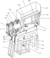
Fig. 1 is a schematic diagram related to the present application.
FIG. 2 is a schematic view of a sequencing slot to which the present application relates.
Reference numbers in the figures: a lifter frame 1; a bottom chassis 101; a guide frame 102; a lifting frame 103; a hand-operated lifting feed screw nut assembly 104; a linear guide 105; a slide table 106; a support plate 107; the roller screening and conveying assembly 2; a conveying motor 201; a feed roller 202; a sorting slot 203; a feeding box 204; a feed inlet 205; a screening port 206; a linear vibration conveying component 3; a vibration feeder 301; a feed rail 302; a feed back port 303; a cushion rubber pad 304; a feed chute 305; a base plate 4; a first support frame 5; a second support 6.
Detailed Description
The technical solutions in the embodiments of the present invention will be described clearly and completely with reference to the accompanying drawings in the embodiments of the present application, and it is obvious that the described embodiments are only some embodiments of the present invention, not all embodiments. Based on the embodiments in the present invention, all other embodiments obtained by a person skilled in the art without creative efforts belong to the protection scope of the present invention.
Example (b):
the utility model provides a screw cylinder screening conveying mechanism, refer to fig. 1 and fig. 2, including elevator frame 1 and locate cylinder screening conveying subassembly 2 and the straight line vibration conveying subassembly 3 on elevator frame 1, elevator frame 1 is including installing bottom frame 101 and the direction frame 102 on the base and locating bottom frame 101, and the crane 103 of being connected with direction frame 102, crane 103's top and cylinder screening conveying subassembly 2 and straight line vibration conveying subassembly 3 are connected, crane 103's bottom and the hand lift screw-nut subassembly 104 that sets up on the bottom frame 101 are connected, crane 103's both sides are connected with the slip table 106 of installing on the direction frame 102 through the linear guide 105 of vertical installation. In the embodiment, the bottom rack 101 is used for supporting the lifting frame 103, the guide rack 102 is used for lifting and guiding the lifting frame 103, and the hand-operated lifting lead screw nut assembly 104 is used for driving the lifting frame 103 to move up and down on the bottom rack 101 and the guide rack 102; specifically, a screw rod in the screw rod nut assembly 104 is lifted by hand, so that the screw rod rotates to ascend or descend under the action of a screw rod nut, and when the screw rod ascends or descends, the screw rod drives the connected lifting frame 103 to ascend or descend on the bottom rack 101 and the guide rack 102 through the linear guide rails 105 on the two sides of the lifting frame 106.
Referring to fig. 1 and 2, the roller screening and conveying assembly 2 comprises a base plate 4 mounted on the lifting frame 103 and a first support frame 5 mounted on the base plate 4, a conveying motor 201 and two feeding rollers 202 connected with the conveying motor 201 are mounted on the first support frame 5, a sorting groove 203 is formed between the two feeding rollers 202, an upper material box 204 connected with a material feeding plate is arranged on the upper side of the sorting groove 203, a material feeding hole 205 corresponding to the sorting groove 203 is formed in the bottom of the upper material box 204, and a screening opening 206 connected with the upper material box 204 is formed in one side of the material feeding hole 205. In this embodiment, the screws on the feed plate enter the feed box 204, enter the sequencing groove 203 through the feed inlet 205 on the feed box 204 and sequence, and then, the feed roller 202 is driven by the conveying motor 201 to rotate so as to drive the screws in the sequencing groove 203 to move towards one side of the linear vibration conveying assembly 3, and when the screws on the sequencing groove 203 are overlapped up and down, the screws enter the feed back port 303 on one side of the linear vibration conveying assembly through the screening port 206 on one side.
Referring to fig. 1, the linear vibration conveying assembly 3 includes a vibration feeder 301 mounted on the bottom plate 4 and a second support frame 6 mounted on the vibration feeder 301, a feeding guide rail 302 connected to the sorting groove 203 is mounted on the second support frame 6, and a material return port 303 connected to the screening port 206 is disposed on one side of the feeding guide rail 302 connected to the sorting groove 203. In this embodiment, in order to alleviate the influence of the vibration feeder 301 on the bottom plate 4, a shock-absorbing rubber pad 304 is installed at the connection position of the vibration feeder 301 and the bottom plate 4, the feeding guide rail 302 is composed of two linear guide rods, a feeding groove 305 connected with the sorting groove 203 is arranged between the two linear guide rods, when the feeding device is used, screws on the sorting groove 203 enter the feeding groove 305 on the feeding guide rail 302, the vibration feeder 201 feeds materials in a vibration mode, and overlapped screws on the sorting groove 203 enter a material return plate through a baffle plate arranged on one side of the material return opening 303, and then the material return plate feeds materials into the storage box for feeding again.
Referring to fig. 1, to facilitate screw movement on the drum screen transport assembly 2 and the linear vibratory transport assembly 3. In the embodiment, the top of the lifting frame 103 is provided with an inclined support plate 107 connected with the bottom plate 4, and the top of the support plate 107 is inclined at an angle of 7 degrees. In other embodiments, the angle at which the top of the support plate 107 is inclined may be set at 3 ° to 12 °.
Specifically, during actual use, screws enter the feeding box 204 through a feeding plate on the pusher, enter the sorting groove 203 between the feeding rollers 202 on two sides through a feeding hole 205 at the bottom of the feeding box 204 and are sorted, the feeding rollers 202 transport the screws on the sorting groove 203 to the feeding guide rail 302 on one side of the linear vibration conveying assembly 3 under the action of the conveying motor 201, the feeding guide rail 302 continues to transport the sorted screws under the action of the vibration feeder 301, when the screws on the sorting groove 203 are stacked up and down, the stacked screws move to the feed back port 303 on one side of the feeding guide rail 302 through the screening port 206, and the stacked screws are pushed to the feed back port 303 through the feed back plate by the arranged baffle plate to enter the storage box for feeding again.
The previous description of the disclosed embodiments is provided to enable any person skilled in the art to make or use the present application. Various modifications to these embodiments will be readily apparent to those skilled in the art, and the generic principles defined herein may be applied to other embodiments without departing from the spirit or scope of the application. Thus, the present application is not intended to be limited to the embodiments shown herein but is to be accorded the widest scope consistent with the principles and novel features disclosed herein.
Claims (5)
1. The utility model provides a screw cylinder screening conveying mechanism, includes elevator frame (1) and locates cylinder screening conveying subassembly (2) and sharp oscillating conveying subassembly (3) on elevator frame (1), its characterized in that:
the roller screening and conveying assembly (2) comprises a bottom plate (4) arranged on the lifting rack (1) and a first support frame (5) arranged on the bottom plate (4), a conveying motor (201) and two feeding rollers (202) connected with the conveying motor (201) are arranged on the first support frame (5), a sorting groove (203) is formed between the two feeding rollers (202), an upper material box (204) connected with the feeding plate is arranged on the upper side of the sorting groove (203), a feeding hole (205) corresponding to the sorting groove (203) is formed in the bottom of the upper material box (204), and a screening opening (206) connected with the upper material box (204) is formed in one side of the feeding hole (205);
linear vibration conveying subassembly (3) are including locating vibration feeder (301) on bottom plate (4) and locating second support frame (6) on vibration feeder (301), be provided with on second support frame (6) with pay-off guide rail (302) that sequencing groove (203) are connected, pay-off guide rail (302) connect in one side of sequencing groove (203) be provided with feed back mouth (303) that screening mouth (206) are connected.
2. The screw roller screening and conveying mechanism according to claim 1, wherein the vibration feeder (301) is disposed on the bottom plate (4) through a shock-absorbing rubber pad (304).
3. A screw roller screening conveyor according to claim 1, characterized in that the feed rail (302) consists of two linear guides between which a feed chute (305) is arranged in connection with the sorting chute (203).
4. The screw roller screening conveying mechanism is characterized in that the lifting frame (1) comprises a bottom frame (101) and a guide frame (102) which are connected with a base and a lifting frame (103) which is arranged on the bottom frame (101) and connected with the guide frame (102), the top of the lifting frame (103) is connected with the bottom plate (4), the bottom of the lifting frame (103) is connected with a hand-operated lifting lead screw nut assembly (104) which is arranged on the bottom frame (101), and two sides of the lifting frame (103) are connected with a sliding table (106) which is arranged on the guide frame (102) through a linear guide rail (105) which is vertically arranged.
5. A screw drum screening conveyor according to claim 4, characterized in that the crane (103) is provided at its top with an inclined support plate (107) connected to the base plate (4).
Priority Applications (1)
| Application Number | Priority Date | Filing Date | Title |
|---|---|---|---|
| CN202222350166.9U CN217971183U (en) | 2022-09-05 | 2022-09-05 | Screw cylinder screening conveying mechanism |
Applications Claiming Priority (1)
| Application Number | Priority Date | Filing Date | Title |
|---|---|---|---|
| CN202222350166.9U CN217971183U (en) | 2022-09-05 | 2022-09-05 | Screw cylinder screening conveying mechanism |
Publications (1)
| Publication Number | Publication Date |
|---|---|
| CN217971183U true CN217971183U (en) | 2022-12-06 |
Family
ID=84262933
Family Applications (1)
| Application Number | Title | Priority Date | Filing Date |
|---|---|---|---|
| CN202222350166.9U Active CN217971183U (en) | 2022-09-05 | 2022-09-05 | Screw cylinder screening conveying mechanism |
Country Status (1)
| Country | Link |
|---|---|
| CN (1) | CN217971183U (en) |
-
2022
- 2022-09-05 CN CN202222350166.9U patent/CN217971183U/en active Active
Similar Documents
| Publication | Publication Date | Title |
|---|---|---|
| CN208616899U (en) | A kind of cardboard automatic charging machine | |
| CN112678214A (en) | Linear filling and capping machine | |
| CN109607155B (en) | Gasket gluing equipment | |
| CN113306760B (en) | Flexible vibration manipulator plate placing machine | |
| CN212953117U (en) | Automatic tray feeding device | |
| CN217971183U (en) | Screw cylinder screening conveying mechanism | |
| CN214451946U (en) | Linear filling and capping machine | |
| CN213922850U (en) | Automatic material placing and taking disc device | |
| CN110127368B (en) | Feeding device of disposable paper pulp dinner plate detection equipment based on machine vision | |
| CN218370352U (en) | Automatic feeding and discharging equipment for plastic uptake box | |
| CN216612881U (en) | Elbow automatic feeding machine | |
| CN212126691U (en) | Screen strorage device | |
| CN214357041U (en) | Anti-overflow module of feeding and food canning device | |
| CN213866745U (en) | Automatic feeding mechanism of pocket flower sewing machine | |
| CN213568441U (en) | Automatic lifting platform for feeding | |
| CN212863027U (en) | Automatic collect product and trade case equipment | |
| CN212638976U (en) | Double-bin feeding mechanism | |
| CN210854139U (en) | Mouse assembly line | |
| CN109823609B (en) | Material arrangement boxing machine | |
| CN217971147U (en) | Screw push plate machine | |
| CN112850029A (en) | Automatic elbow feeding device and feeding method | |
| CN219154807U (en) | Flexible vibration manipulator disc arranging machine | |
| CN217171941U (en) | Lifting device is carried to packing box | |
| CN217570734U (en) | Circulating automatic riveting machine | |
| CN212607980U (en) | Push pedal type automatic feeding machine |
Legal Events
| Date | Code | Title | Description |
|---|---|---|---|
| GR01 | Patent grant | ||
| GR01 | Patent grant |