CN217947255U - Automatic winding mechanism for cable reel - Google Patents
Automatic winding mechanism for cable reel Download PDFInfo
- Publication number
- CN217947255U CN217947255U CN202122790284.7U CN202122790284U CN217947255U CN 217947255 U CN217947255 U CN 217947255U CN 202122790284 U CN202122790284 U CN 202122790284U CN 217947255 U CN217947255 U CN 217947255U
- Authority
- CN
- China
- Prior art keywords
- cable
- electric
- assembly
- mounting seat
- reel
- Prior art date
- Legal status (The legal status is an assumption and is not a legal conclusion. Google has not performed a legal analysis and makes no representation as to the accuracy of the status listed.)
- Active
Links
Images


Abstract
The utility model provides an automatic winding mechanism of a cable drum, which comprises a cable drum component, a driving component and a torsion sensor, wherein the cable drum component is arranged at the top end of the driving component, and the torsion sensor is arranged between the driving component and the cable drum component; an electric cable is arranged on the cable reel component; the cable reel assembly comprises an electric slip ring and a cable reel, and a cable cylinder which is recessed downwards is arranged at the top end of the cable reel; an electric slip ring fixed on the cable tray is arranged at the top end of the cable drum; according to the structure, the tension of the electric cable is detected in real time through the torsion sensor, and the driving assembly is controlled to drive the cable reel assembly according to the tension feedback of the electric cable; therefore, the electric cable can be wound or loosened, the tension of the electric cable is controlled to be in a control range, and the electric cable is protected from being pulled and wound.
Description
Technical Field
The utility model belongs to the cable lays, removes the power supply field, especially relates to a cable dish automatic winding mechanism.
Background
Along with the development of building technology, more and more building sites begin to use mobile robot to participate in corresponding building work, because the building place is big, the site environment is more complicated, and the commercial power cable line can not be fine in the robot removes work used, and portable robot power supply uses the lithium cell as the owner at present, leads to the unable too powerful equipment of carrying of portable robot to carry out the operation, and the continuous working ability is low, and efficiency is not high.
In the prior art, for example, a patent document having a chinese patent application No. 201410224414.2 and a publication date 2014.07.30 discloses an automatic cable winding and unwinding device, which is characterized in that the automatic cable winding and unwinding device comprises a rear shell, a front left shell, a front right shell, a cable winding device, a cable arranging device, a power supply, a controller and a display device; the power supply, the controller and the display device are positioned in the rear shell, and a display and operation panel of the display device is arranged on the upper surface of the rear shell; the front left shell can move in a sliding groove on the front end surface of the rear shell; the disc left edge indicating component is positioned right above the coiling transmission component, and the disc right edge indicating component is positioned right above the disc clamping component; the controller controls the rotation of the cable coiling motor and the movement of the wire arranging motor by setting the wire coiling pitch, the diameter of the cable, the wire coiling total length estimated value or the wire releasing total length value through the operation on the display and operation panel, but the pulling force feedback to the cable is lacked in practical application, and the speed of coiling and uncoiling the cable is difficult to be completely synchronous with the speed of a vehicle.
Disclosure of Invention
An object of the utility model is to provide a cable dish automatic winding mechanism has automatic control and receives and unreel, makes the tension control of cable line in certain extent, and protection cable line is not dragged, twines, very big extension cable rope life, still have receive and release the cable fast, characteristics such as efficient have saved the cost of labor who receive and releases the cable greatly.
In order to achieve the purpose, the automatic cable reel winding mechanism comprises a cable reel assembly, a driving assembly and a torsion sensor, wherein the cable reel assembly is arranged at the top end of the driving assembly, and the torsion sensor is arranged between the driving assembly and the cable reel assembly; an electric cable is arranged on the cable reel component; the cable reel assembly comprises an electric slip ring and a cable reel, and a cable cylinder which is recessed downwards is arranged at the top end of the cable reel; an electric slip ring fixed on the cable tray is arranged at the top end of the cable drum.
According to the structure, the tension of the electric cable is detected in real time through the torsion sensor, and the driving assembly is controlled to drive the cable reel assembly according to the tension feedback of the electric cable; when the torque sensor detects that the tension feedback of the electric cable is too small, the cable disc assembly is driven to wind the electric cable, and when the torque sensor detects that the tension feedback of the electric cable is too large, the cable disc assembly is driven to release the electric cable, so that the electric cable is wound or loosened, the tension of the electric cable is controlled to be ensured in a control range, and the electric cable is protected from being pulled and wound.
Furthermore, a cable channel extending into the cable drum is arranged on the side edge of the cable disc; one end of the electric cable penetrates through the cable channel and extends into the cable barrel and is connected with the electric slip ring, a driving assembly is arranged at the bottom end of the cable disc, and the driving assembly is connected with the torque sensor.
Above setting, when installation electric cable line, pass the cable passageway with electric cable line one end and stretch into a cable section of thick bamboo and connect the electrical slip ring, then electric cable line's installation can be accomplished to the other end winding back on the cable dish, and is simple and convenient.
Further, drive assembly includes pivot, bearing frame, goes up the shaft coupling, goes up the mount pad, lower shaft coupling, synchronous belt drive subassembly and motor, go up the mount pad setting on the mount pad down, locate the bearing frame on last mount pad, be located and be equipped with the pivot in the bearing frame, the top of pivot is through pivot seat connection cable dish, the upper end of last coupling joint torque sensor is passed through to the bottom of pivot, synchronous belt drive subassembly sets up the below of mount pad under, torque sensor's lower extreme passes down the mount pad through lower shaft coupling and connects synchronous belt drive subassembly, the motor is installed under on the mount pad and is connected with synchronous belt drive subassembly.
According to the arrangement, when the torque sensor detects that the tension feedback of the cable is too small, the driving motor rotates to drive the cable disc connected with the rotating shaft to rotate to wind the cable, and when the torque sensor detects that the tension feedback of the cable is too large, the driving motor rotates to drive the cable disc connected with the rotating shaft to rotate to unwind the cable.
Furthermore, synchronous belt drive assembly includes initiative synchronizing wheel, driven synchronizing wheel and belt, the initiative synchronizing wheel is connected with the output of motor, the driven synchronizing wheel is connected with the shaft coupling down, is equipped with the belt between initiative synchronizing wheel and driven synchronizing wheel.
Above setting, when needing to receive and release the hawser, the motor drives the initiative synchronizing wheel rotates, the initiative synchronizing wheel passes through the belt drives driven synchronizing wheel and rotates, thereby rotates power input control cable dish in the lower shaft coupling, controls receiving and releasing of hawser from this, has to receive and release that the cable is fast, efficient characteristics, has saved the cost of labor who receive and releases the cable greatly.
Furthermore, the upper mounting seat is provided with a bearing hole, and the lower end of the lower coupler penetrates through the bearing hole to be connected with the driven synchronizing wheel.
The lower end of the lower coupler penetrates through the bearing hole to be connected with the driven synchronizing wheel, so that the consumption of power transmission is reduced, the structure is simple, and energy is saved.
Drawings
Fig. 1 is the utility model discloses be applied to an inner structure schematic diagram of mobilizable intelligent butt joint cable dish.
Fig. 2 is the structure diagram of the automatic winding mechanism for cable reel of the present invention.
Fig. 3 is the utility model discloses be applied to a first visual angle external structure schematic diagram of mobilizable intelligent butt joint cable dish.
Fig. 4 is the utility model discloses a be applied to a second visual angle external structure schematic diagram of mobilizable intelligent butt joint cable dish.
Fig. 5 is the utility model discloses a be applied to the view of a bottom of a mobilizable intelligent butt joint cable dish.
Fig. 6 is the utility model discloses a be applied to a plug and socket connection diagram of mobilizable intelligent butt joint cable dish.
Fig. 7 is the utility model discloses a be applied to a circuit connection diagram of mobilizable intelligent butt joint cable drum.
Fig. 8 is a cross-sectional view of the cable tray assembly of the present invention.
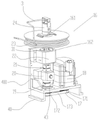
In the figure: the electric slip ring 24, the cable drum 23, the cable drum 231, the rotating shaft 31, the bearing seat 22, the upper coupling 21, the torsion sensor 20, the lower coupling 19, the synchronous belt transmission assembly 17, the driving synchronous wheel 171, the driven synchronous wheel 172, the belt 173, the motor 18, the upper mounting seat 40, the lower mounting seat 400, the bearing hole 43, the automatic cable drum winding mechanism 16, the cable drum assembly 161, the driving assembly 162, the mobile chassis 13, the outer shell 50, the laser slam navigation 8, the ultrasonic sensor 9, the camera 10, the two-dimensional code 12, the bottom plate 28, the driving wheel 25, the mobile motor 26, the universal wheel 27, the plug 30, the socket 29, the pulley 15, the pulley support 151, the intelligent mobile cable drum 2, the cable rope 3, the construction robot 5 and the distribution box 1.
Detailed Description
The present invention will be described in further detail with reference to the accompanying drawings and specific embodiments.
As shown in fig. 1, the automatic winding mechanism for the cable drum is applied to a movable intelligent docking cable drum, and the intelligent docking cable drum comprises more than one intelligent mobile cable drum, an electric cable, a building robot and a distribution box.
Every intelligent movement cable drum 2 is through electric cable 3 interconnect, form an uninterrupted line through electric cable 3 connection between every intelligent movement cable drum 2, the intelligent movement cable drum 2 that is located the circuit front end passes through cable rope 3 and is connected with block terminal 1, and the intelligent movement cable drum 2 that is located the circuit end passes through electric cable 3 and links to each other with construction robot 5, intelligent movement cable drum 2 includes cable drum automatic winding mechanism 16, outside casing 50 and removes chassis 13, outside casing 50 sets up on removing chassis 13, is equipped with cable drum automatic winding mechanism 16 in the outside casing 50, cable drum automatic winding mechanism 16 includes cable drum subassembly 161, drive assembly 162 and torque sensor 21, cable drum subassembly 161 sets up on the top of drive assembly 162, sets up torque sensor 21 between drive assembly 162 and cable drum subassembly 161.
In the present embodiment, the construction robot 5 is a robot applied to construction site assistance, and the specific construction robot 5 is a related art, which will not be described in detail below.
According to the structure, the intelligent mobile cable reel 2 is connected through the cable rope 3 to form an uninterrupted line, so that the construction robot 5 can adapt to construction work in sites with different sizes, and the cable rope 3 required by a construction site can be automatically wound and unwound by arranging the automatic cable reel winding mechanism 16, so that the situation that the cable rope 3 is not easy to fall in the site in the construction site, personnel cannot walk conveniently, the cable rope 3 is protected from being pulled and wound, and the service life of the cable rope 3 is greatly prolonged; when the building robot works, the building robot 5 pulls the electric cable 3 in the moving process, the torsion sensor 21 detects the tension on the electric cable 3 when the building robot 5 moves in real time, and the torsion sensor 21 controls the driving assembly 162 to drive the cable reel assembly 161 according to the tension feedback of the electric cable 3; when the torque sensor 20 detects that the tension feedback of the construction robot 5 is too small, the cable reel assembly 161 is driven to wind the electric cable 3, and when the torque sensor 21 detects that the tension feedback of the construction robot 5 is too large, the cable reel assembly 161 is driven to release the cable 3, so that the electric cable 3 is wound or loosened, the tension of the electric cable 3 is controlled to be within a control range, and the electric cable 3 is protected from being pulled and wound.
As shown in fig. 1 and 2, the cable drum assembly 161 includes an electrical slip ring 24 and a cable drum 23, and a cable drum 231 recessed downward is disposed at a top end of the cable drum 23; an electric slip ring 24 fixed on the cable drum 23 is arranged at the top end of the cable drum 231, and a cable channel extending into the cable drum 231 is arranged at the side edge of the cable drum 23; one end of the electric cable 3 passes through the cable channel and extends into the cable drum 231 and is connected with the electric slip ring 24, a driving assembly 162 is arranged at the bottom end of the cable disc 23, and the driving assembly 162 is connected with the torque sensor 20.
Above setting, when installation electric cable 3, pass the cable passageway with electric cable 3 one end and stretch into cable section of thick bamboo 231 and connect electrical slip ring 24, then electric cable 3's the other end winding can accomplish electric cable 3's installation after on cable dish 23, simple and convenient.
As shown in fig. 1 and 2, the driving assembly includes a rotating shaft 31, a bearing seat 22, an upper coupler 21, an upper mounting seat 40, a lower coupler 19, a synchronous belt transmission assembly 17 and a motor 18, the upper mounting seat 40 is disposed on the lower mounting seat 400, the bearing seat 43 is disposed on the upper mounting seat 40, the rotating shaft 31 is disposed in the bearing seat 43, the top end of the rotating shaft 31 is connected with a cable tray 23 through the rotating shaft seat 43, the bottom end of the rotating shaft 31 is connected with the upper end of the torsion sensor 20 through the upper coupler 21, the synchronous belt transmission assembly 17 is disposed below the lower mounting seat 400, the lower end of the torsion sensor 20 penetrates through the lower mounting seat 400 through the lower coupler 19 to be connected with the synchronous belt transmission assembly 17, and the motor 18 is mounted on the lower mounting seat 400 and connected with the synchronous belt transmission assembly 17; the torque sensor 20 is electrically connected to the motor 18.
With the above arrangement, when the torque sensor 20 detects that the tension feedback of the construction robot 5 is too small, the driving motor 18 rotates to drive the cable disc 23 connected with the rotating shaft 31 to rotate to wind the cable 3, and when the torque sensor 20 detects that the tension feedback of the construction robot 5 is too large, the driving motor 18 rotates to drive the cable disc 23 connected with the rotating shaft 31 to rotate to unwind the cable 3.
As shown in fig. 1-6, the cable reel assembly 161 further comprises a plug 30 and a socket 29, the plug 30 is disposed at the front end of the outer casing 50, the socket 29 is disposed at the rear end of the outer casing 50, one end of the electric cable 3 is connected to the socket 29 through the electric slip ring 24, the other end of the electric cable 3 is connected to the plug 30, the plug 30 on one intelligent mobile cable reel 16 is connected to the socket 29 of the other intelligent mobile cable reel 16 to form a line, a pulley 15 is further disposed in the outer casing 50, the pulley 15 is disposed on the inner wall of the front end of the outer casing 50 through a pulley support 151, and the electric cable 3 is connected to the plug 30 through the pulley 15; through the arrangement of the pulley 15, the cable winding and unwinding of the plug 30 is uniform and stable, and the cable 3 is protected from being pulled and wound.
With the above arrangement, the electrical slip ring 24 can prevent the cable rope 3 from being wound when the cable drum 23 rotates, so that the rotation of the cable drum 23 does not affect the socket 29.
As shown in fig. 1 and 2, the synchronous belt drive assembly 17 includes a driving synchronous pulley 171, a driven synchronous pulley 172 and a belt 173, the driving synchronous pulley 171 is connected to an output end of the motor 18, the driven synchronous pulley 172 is connected to the lower coupling 19, and the belt 173 is disposed between the driving synchronous pulley 171 and the driven synchronous pulley 172.
Above setting, when needing to receive and release the hawser, motor 18 drives initiative synchronizing wheel 171 rotates, initiative synchronizing wheel 171 passes through belt 173 drives driven synchronizing wheel 172 and rotates, thereby rotates power input control cable dish 23 in the lower shaft coupling 19, controls receiving and releasing of hawser 3 from this, has to receive and release that the cable is fast, efficient characteristics, has saved the cost of labor of receiving and releasing the cable greatly.
As shown in fig. 1 and 2, the upper mounting seat 40 is provided with a bearing hole 43, and the lower end of the lower coupling 19 passes through the bearing hole 43 and is connected to the driven synchronizing wheel 172.
With the arrangement, the lower end of the lower coupling 19 penetrates through the bearing hole 43 to be connected with the driven synchronizing wheel 172, so that the power transmission consumption is reduced, the structure is simple, and the energy is saved.
As shown in fig. 5, the moving chassis 13 includes a bottom plate 28, a driving wheel 25, a moving motor 26, and a universal wheel 27, wherein the driving wheel 25 is fixed on the rear end of the bottom plate 28 through the moving motor 26, and the universal wheel 27 is disposed on the front end of the bottom plate 28.
The arrangement is such that the moving motor 26 drives the driving wheel 25 to move forward or backward.
As shown in fig. 3 and 4, a laser slam navigator 8, an ultrasonic sensor 9 and a camera 10 are arranged on the front side of the outer casing 50, the camera 10 is arranged at the front end of the outer casing 50, the ultrasonic sensor 9 is arranged on the outer casing 50 below the camera 10, and the laser slam navigator 8 is arranged below the ultrasonic sensor 9.
Above setting, laser slam navigation 8 effect is the scanning area environment, establishes map navigation and control remove chassis 13 and remove, realizes the mobile location of intelligent movement cable drum 16, ultrasonic sensor 9's effect is to avoid the barrier, and automatic removal work has saved the cost of labor who receive and releases the cable greatly, uses the method that laser slam navigation 8 and camera 10 location combined together to improve the accuracy of navigation effectively moreover.
As shown in fig. 1 and 2, the rear end or the side end of the external shell 50 is provided with the two-dimensional code 12, and after each intelligent mobile cable reel 2 is moved, the intelligent mobile cable reel 2 at the rear scans the two-dimensional code 12 on the intelligent mobile cable reel 2 in front through the camera 10 by setting the two-dimensional code 12, so that the intelligent mobile cable reel 2 is identified and secondarily positioned, and the position of the intelligent mobile cable reel 2 is more accurate.
In this embodiment, the laser slam navigator 8, the ultrasonic sensor 9 and the camera 10 are electrically connected with the moving chassis 13.
Above setting, navigation control through laser slam navigation 8 and camera 10 removes chassis 13 and carries out the location removal, removes chassis 13 through ultrasonic sensor 9 control and keeps away the barrier removal, guarantees from this that the position that 2 moves of intelligent movement cable reels is more accurate.
Above-mentioned structure, when needs connect every intelligent movement cable drum 2, every intelligent movement cable drum 2 confirms the position of removal through the map navigation that laser slam navigation 8 established, the in-process of removal realizes keeping away the barrier through ultrasonic sensor 9, after intelligent movement cable drum removes 2 to the appointed position of map navigation, the intelligent movement cable drum 2 that is located the rear realizes the secondary localization through two-dimensional code 12 on the intelligent movement cable drum 2 of camera 10 scanning the place ahead, in inserting the socket 29 on another intelligent movement cable drum 2 with the cable rope 3 that is connected with plug 30 on every intelligent movement cable drum 2 after the location is accomplished, accomplish the connection between the intelligent movement cable drum 2 from this, it is simple and convenient.
Claims (5)
1. The utility model provides a cable dish automatic winding mechanism which characterized in that: the cable drum assembly is arranged at the top end of the driving assembly, and the torsion sensor is arranged between the driving assembly and the cable drum assembly; an electric cable is arranged on the cable reel component; the cable reel assembly comprises an electric slip ring and a cable reel, and a cable cylinder which is recessed downwards is arranged at the top end of the cable reel; an electric slip ring fixed on the cable tray is arranged at the top end of the cable drum.
2. The automatic winding mechanism of cable reel of claim 1, wherein: a cable channel extending into the cable drum is arranged on the side edge of the cable tray; one end of the electric cable penetrates through the cable channel and extends into the cable barrel and is connected with the electric slip ring, a driving assembly is arranged at the bottom end of the cable disc, and the driving assembly is connected with the torque sensor.
3. The automatic winding mechanism of the cable reel as claimed in claim 1, wherein: the drive assembly comprises a rotating shaft, a bearing seat, an upper coupler, an upper mounting seat, a lower coupler, a synchronous belt transmission assembly and a motor, wherein the upper mounting seat is arranged on the lower mounting seat, the bearing seat is arranged on the upper mounting seat, a rotating shaft is arranged in the bearing seat, the top end of the rotating shaft is connected with a cable disc through the rotating shaft seat, the bottom end of the rotating shaft is connected with the upper end of a torque sensor through the upper coupler, the synchronous belt transmission assembly is arranged below the lower mounting seat, the lower end of the torque sensor penetrates through the lower coupler to be connected with the synchronous belt transmission assembly through the lower mounting seat, and the motor is arranged on the lower mounting seat and is connected with the synchronous belt transmission assembly.
4. The automatic winding mechanism of cable reel of claim 3, wherein: the synchronous belt transmission assembly comprises a driving synchronous wheel, a driven synchronous wheel and a belt, the driving synchronous wheel is connected with the output end of the motor, the driven synchronous wheel is connected with the lower coupler, and the belt is arranged between the driving synchronous wheel and the driven synchronous wheel.
5. The automatic winding mechanism of cable reel of claim 4, wherein: the upper mounting seat is provided with a bearing hole, and the input end of the lower coupler penetrates through the bearing hole to be connected with the driven synchronizing wheel.
Priority Applications (1)
| Application Number | Priority Date | Filing Date | Title |
|---|---|---|---|
| CN202122790284.7U CN217947255U (en) | 2021-11-15 | 2021-11-15 | Automatic winding mechanism for cable reel |
Applications Claiming Priority (1)
| Application Number | Priority Date | Filing Date | Title |
|---|---|---|---|
| CN202122790284.7U CN217947255U (en) | 2021-11-15 | 2021-11-15 | Automatic winding mechanism for cable reel |
Publications (1)
| Publication Number | Publication Date |
|---|---|
| CN217947255U true CN217947255U (en) | 2022-12-02 |
Family
ID=84209055
Family Applications (1)
| Application Number | Title | Priority Date | Filing Date |
|---|---|---|---|
| CN202122790284.7U Active CN217947255U (en) | 2021-11-15 | 2021-11-15 | Automatic winding mechanism for cable reel |
Country Status (1)
| Country | Link |
|---|---|
| CN (1) | CN217947255U (en) |
-
2021
- 2021-11-15 CN CN202122790284.7U patent/CN217947255U/en active Active
Similar Documents
| Publication | Publication Date | Title |
|---|---|---|
| CN105692355A (en) | Robot device capable of automatically reeling and unreeling electric cable or optical cable | |
| CN116184373A (en) | Sonar device for underwater topography exploration | |
| CN210854820U (en) | Power transmission line pay-off | |
| CN217947255U (en) | Automatic winding mechanism for cable reel | |
| KR100994460B1 (en) | Moveable type utility supplying units for lug welding robot | |
| CN218788622U (en) | Cable pipeline walking device and electric cable threading device | |
| CN110581459A (en) | Threading construction auxiliary device for building electrical engineering and use method thereof | |
| CN217823566U (en) | Automatic winding and unwinding mechanism of rifle line that charges and automatic electric pile that fills | |
| CN113955592A (en) | Working method of movable intelligent butt-joint cable reel | |
| CN113998547A (en) | Movable intelligent butt-joint cable reel | |
| CN209815411U (en) | Automatic winding and unwinding device for staying unmanned aerial vehicle | |
| KR200389079Y1 (en) | Puller tensioner for Installing Transmission Line | |
| CN110994424B (en) | Substation equipment inspection detection device | |
| CN210480438U (en) | Winding device | |
| CN210757760U (en) | Cable pipeline robot and system based on curved surface geometric constraint kinematics model | |
| CN214243322U (en) | Mobile energy storage vehicle with electric cabinet | |
| CN219408628U (en) | Underground cable exhibition equipment of putting | |
| CN219217136U (en) | Fast winding and unwinding auxiliary device for wharf boat shore power charging cable | |
| CN215558106U (en) | Long-distance cable winding and unwinding device | |
| CN219708783U (en) | Offshore cable laying device | |
| CN116014635B (en) | Pre-buried pipeline wiring device and use method | |
| CN220844966U (en) | Rotary marine cable collecting and discharging auxiliary tool | |
| CN201181831Y (en) | Cable reel control device | |
| CN213394208U (en) | Artificial intelligence security equipment based on 5G | |
| CN220245153U (en) | Automatic unreel power cable spool |
Legal Events
| Date | Code | Title | Description |
|---|---|---|---|
| GR01 | Patent grant | ||
| GR01 | Patent grant |