CN217885579U - Well island cabinet - Google Patents
Well island cabinet Download PDFInfo
- Publication number
- CN217885579U CN217885579U CN202221397238.9U CN202221397238U CN217885579U CN 217885579 U CN217885579 U CN 217885579U CN 202221397238 U CN202221397238 U CN 202221397238U CN 217885579 U CN217885579 U CN 217885579U
- Authority
- CN
- China
- Prior art keywords
- base
- cabinet
- seat
- supporting seat
- display cabinet
- Prior art date
- Legal status (The legal status is an assumption and is not a legal conclusion. Google has not performed a legal analysis and makes no representation as to the accuracy of the status listed.)
- Active
Links
Images


Landscapes
- Devices For Indicating Variable Information By Combining Individual Elements (AREA)
Abstract
The application discloses well island cabinet relates to the relevant technical field of show cupboard, includes: the display cabinet comprises a base, wherein a placing groove is formed in the middle of the base, a display cabinet is arranged in the placing groove, and a lifting mechanism is arranged between the display cabinet and the base; the lifting mechanism comprises a supporting seat arranged in the placing groove, the supporting seat is rotationally connected with the base, a sliding groove is formed in the middle of the supporting seat, a movable seat is arranged in the sliding groove in a sliding mode, the movable seat is fixedly connected with the display cabinet, a rack is arranged in the sliding groove, the rack is fixedly connected with the movable seat, a lifting motor is fixedly arranged outside the supporting seat, the output end of the lifting motor penetrates through the supporting seat and is fixedly connected with a lifting gear, and the lifting gear is meshed with the rack; this application can adjust the occupation space of show cupboard, can adjust usable floor area, can improve the bandwagon effect simultaneously.
Description
Technical Field
The application relates to the technical field of show cupboard is relevant, especially relates to a well island cabinet.
Background
With the development of society, the living world of human beings is colorful, and various products and creations are continuously full of the eyes of people. The product notification needs to be realized by attractive propaganda means, and the product display becomes one of the important marketing means of the current merchants. Among them, the choice of the place for product display and the display mode adopted are very important.
The island cabinet is a common display cabinet, and the island cabinet is a goods shelf for displaying goods, but the island cabinet occupies a large area at present and is easy to touch other articles during movement.
SUMMERY OF THE UTILITY MODEL
In order to solve the present area occupied of well island cabinet great, run into the problem of other article easily when removing, this application provides a well island cabinet.
The application provides a well island cabinet adopts following technical scheme:
an island cabinet comprising:
the display cabinet comprises a base, wherein a placing groove is formed in the middle of the base, a display cabinet is arranged inside the placing groove, and a lifting mechanism is arranged between the display cabinet and the base;
elevating system is including setting up the supporting seat in putting inslot portion, just rotate between supporting seat and the base and be connected, the spout has been seted up at the middle part of supporting seat, the inside slip of spout is provided with the sliding seat, fixed connection between sliding seat and the show cupboard, the inside of spout is provided with the rack, fixed connection between rack and the sliding seat, the fixed elevator motor that is provided with in outside of supporting seat, elevator motor's output runs through the supporting seat to fixedly connected with lifting gear, the meshing is connected between lifting gear and the rack.
By adopting the technical scheme: the lifting gear is driven to rotate through the lifting motor, the rack is driven to move through the lifting gear, and the movable seat is driven to synchronously move through the rack, so that the movable seat drives the display cabinet to perform height adjustment.
Optionally, the base is symmetrically and fixedly provided with slide rails inside the placing groove, the two sides of the display cabinet are both fixedly provided with slide blocks, and the slide blocks are arranged inside the slide rails in a sliding manner.
By adopting the technical scheme: the sliding block is limited by sliding through the arranged sliding rail, and the display cabinet is limited synchronously by the sliding block.
Optionally, a support frame is fixedly arranged on one side of the base, which is located on the support seat, and a rotating mechanism is arranged between the support frame and the support seat.
By adopting the technical scheme: the supporting frame is used for rotating the rotating mechanism.
Optionally, the rotating mechanism includes a worm wheel fixedly sleeved on the supporting seat, a worm is rotatably arranged in the middle of the supporting frame, the worm and the worm wheel are meshed and connected, a rotating motor is fixedly arranged on one side of the supporting frame, and an output end of the rotating motor is fixedly connected with the worm.
By adopting the technical scheme: the worm is driven to rotate by the arranged rotating motor, so that the worm drives the worm wheel to rotate, and the worm wheel drives the display cabinet to rotate.
Optionally, the both sides symmetry of base has seted up the spacing groove, the inside of spacing groove all is provided with the extension board, be provided with telescopic machanism between extension board and the base.
By adopting the technical scheme: the extending plate is supported in a sliding mode through the limiting groove.
Optionally, the telescopic mechanism includes micro gears symmetrically and rotatably arranged inside the base, the two micro gears are in meshed connection, a folding rod is fixedly connected to the micro gears, one end of the folding rod, which is far away from the micro gears, is rotatably connected to the extension plate, a telescopic motor is fixedly arranged outside the base, and an output end of the telescopic motor is fixedly connected to one micro gear; the middle part of folding rod is articulated setting, and two folding opposite direction of folding rod.
By adopting the technical scheme: the micro gear is driven to rotate by the telescopic motor, so that the micro gear drives the extension plate to slide in position through the folding rod; the folding directions of the two folding rods are opposite, so that the extension plates can be synchronously supported.
Optionally, the display cabinet is in an annular arrangement, one side of the display cabinet is provided with a cabinet door, the cabinet door and the display cabinet are slidably arranged, and the cabinet door is provided with a handle.
By adopting the technical scheme: the display cabinet is controlled to be opened and closed through the cabinet door, and the cabinet door is controlled through the handle.
Compared with the prior art, the beneficial effects of this application are:
1. in this application, mutually support between through elevator motor, lifting gear, rack, spout to drive the sliding seat through the rack and carry out synchronous slip, drive the show cupboard through the sliding seat and go up and down, adjust the occupation space of show cupboard.
2. In this application, through mutually supporting between rotating motor, worm wheel, the supporting seat, make the supporting seat drive the show cupboard and rotate, improve the bandwagon show effect.
3. In this application, mutually support between motor, two micro-gear, two folding rods through flexible, make two folding rods can carry out synchronous promotion to the extension board, make the extension board carry out the position in the inside of spacing groove and slide, adjust usable floor area.
Drawings
FIG. 1 is a schematic perspective view of the present application;
FIG. 2 is a side cross-sectional structural view of the present application;
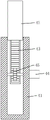
FIG. 3 is a schematic view of the lifting mechanism of the present application;
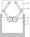
fig. 4 is a schematic structural diagram of the telescopic mechanism in the present application.
Description of reference numerals: 1. a base; 2. a placing groove; 3. a display cabinet; 31. a cabinet door; 32. a handle; 4. a lifting mechanism; 41. a supporting base; 42. a movable seat; 43. a rack; 44. a lifting motor; 45. a lifting gear; 5. a slide rail; 6. a slider; 7. a support frame; 8. a rotating mechanism; 81. a worm gear; 82. a worm; 83. rotating the motor; 9. a limiting groove; 10. an extension plate; 11. a telescoping mechanism; 111. a micro gear; 112. a folding bar; 113. a telescopic motor.
Detailed Description
The present application is described in further detail below with reference to figures 1-4.
Examples
The present application provides the following technical solutions, please refer to fig. 1, the island cabinet includes: to this application whole base 1 that supports, place groove 2 has been seted up at base 1's middle part, the inside of placing groove 2 is provided with show cupboard 3, place groove 2 through the setting and deposit show cupboard 3, wherein show cupboard 3 is the annular setting, one side of show cupboard 3 is provided with cabinet door 31, be convenient for open and shut the control to the inside of show cupboard 3 through the cabinet door 31 that sets up, slide between cabinet door 31 and the show cupboard 3 and set up, and be provided with handle 32 on the cabinet door 31, be convenient for carry out control operation to cabinet door 31 through the handle 32 that sets up.
Please refer to fig. 2 and fig. 3, in order to save the occupied space of the display cabinet 3, and at the same time, it is convenient to move the whole display cabinet 3, a lifting mechanism 4 is disposed between the display cabinet 3 and the base 1, the lifting mechanism 4 includes a supporting seat 41 disposed inside the placing groove 2, and the supporting seat 41 is rotatably connected with the base 1, the supporting seat 41 is rotatably supported by the base 1, a sliding groove is disposed at the middle of the supporting seat 41, a movable seat 42 is slidably disposed inside the sliding groove, the movable seat 42 is slidably supported by the sliding groove, the movable seat 42 is fixedly connected with the display cabinet 3, the movable seat 42 is fixedly supported by the sliding groove, a lifting motor 44 is fixedly disposed outside the supporting seat 41, an output end of the lifting motor 44 penetrates through the supporting seat 41, and is fixedly connected with a lifting gear 45, the lifting gear 45 is engaged with the rack 43, the lifting motor 44 is fixedly supported by the supporting seat 41, and the lifting motor 44 is driven by the lifting gear 45.
Referring to fig. 2, the base 1 is symmetrically and fixedly provided with slide rails 5 inside the placing groove 2, the slide rails 5 are fixedly supported by the base 1, the sliding blocks 6 are fixedly arranged on both sides of the display cabinet 3, the sliding blocks 6 are slidably arranged inside the slide rails 5, the sliding blocks 6 are slidably limited by the slide rails 5, and the display cabinet 3 is synchronously limited by the sliding blocks 6.
Referring to fig. 2, a supporting frame 7 is fixedly disposed on one side of the supporting base 41 of the base 1, and the supporting frame 7 is fixedly supported by the disposed base 1.
Please refer to fig. 2, wherein in order to facilitate the rotation of the display cabinet 3, the display effect is improved, a rotating mechanism 8 is arranged between the support frame 7 and the support seat 41, the rotating mechanism 8 includes a worm wheel 81 fixedly sleeved on the support seat 41, the worm wheel 81 is fixedly supported by the support seat 41, and the support seat 41 is driven to rotate by the worm wheel 81, a worm 82 is arranged at the middle of the support frame 7 in a rotating manner, the worm 82 is meshed with the worm wheel 81, a rotating motor 83 is fixedly arranged at one side of the support frame 7, the output end of the rotating motor 83 is fixedly connected with the worm 82, the rotating motor 83 is fixedly supported by the support frame 7, the worm 82 is driven to rotate by the rotating motor 83, and the worm wheel 81 is driven to synchronously rotate by the worm 82.
Referring to fig. 1, the base 1 is symmetrically provided with limiting grooves 9 at both sides, the extending plates 10 are disposed inside the limiting grooves 9, the extending plates 10 are slidably supported by the limiting grooves 9, and the usable area of the base 1 is increased by the extending plates 10.
Referring to fig. 2 and 4, in order to adjust the usable area of the extension board 10, a telescopic mechanism 11 is disposed between the extension board 10 and the base 1, the telescopic mechanism 11 includes micro gears 111 symmetrically and rotatably disposed inside the base 1, the two micro gears 111 are engaged and connected, the micro gears 111 are rotatably supported by the base 1, one micro gear 111 is rotated to drive the other micro gear 111 to synchronously and reversely rotate, a folding rod 112 is fixedly connected to the micro gear 111, one end of the folding rod 112, which is far away from the micro gear 111, is rotatably connected to the extension board 10, the middle of the folding rod 112 is hinged, the two folding rods 112 are oppositely folded, the two folding rods 112 are driven to synchronously and reversely rotate by the rotation of the two micro gears 111, the two folding rods 112 are capable of synchronously pushing the extension board 10, the extension board 10 slides inside the limiting groove 9 in position, the usable area is adjusted, a telescopic motor 113 is fixedly disposed outside the base 1, an output end of the telescopic motor 113 is fixedly connected to one micro gear 111, the base 1 fixedly supports the telescopic motor 113, and drives the micro gear 111 to rotate.
The implementation principle of the embodiment of the application is as follows:
during the use, start elevator motor 44, the output through elevator motor 44 drives lifting gear 45 and rotates, drives rack 43 through lifting gear 45 and carries out the position slip inside the spout to drive sliding seat 42 through rack 43 and carry out the synchronous slip, drive show cupboard 3 through sliding seat 42 and go up and down, adjust the occupation space of show cupboard 3.
Start rotating motor 83, drive worm 82 through the output that rotates motor 83 and rotate, drive worm wheel 81 through worm 82 and carry out synchronous rotation, drive supporting seat 41 through worm wheel 81 and carry out synchronous rotation, make supporting seat 41 drive show cupboard 3 and rotate, improve show cupboard 3's bandwagon effect.
Start flexible motor 113, output through flexible motor 113 drives a micro-gear 111 and rotates to make a micro-gear 111 drive another micro-gear 111 and carry out synchronous antiport, drive two folding rods 112 through two micro-gears 111 and carry out synchronous antiport, make two folding rods 112 can carry out synchronous promotion to extension board 10, make extension board 10 carry out the position in the inside of spacing groove 9 and slide, adjust usable floor area.
The above embodiments are preferred embodiments of the present application, and the protection scope of the present application is not limited by the above embodiments, so: all equivalent changes made according to the structure, shape and principle of the present application shall be covered by the protection scope of the present application.
Claims (7)
1. An island cabinet, comprising:
the display cabinet comprises a base (1), wherein a placement groove (2) is formed in the middle of the base (1), a display cabinet (3) is arranged inside the placement groove (2), and a lifting mechanism (4) is arranged between the display cabinet (3) and the base (1);
elevating system (4) including setting up supporting seat (41) putting groove (2) inside, just rotate between supporting seat (41) and base (1) and be connected, the spout has been seted up at the middle part of supporting seat (41), the inside slip of spout is provided with sliding seat (42), fixed connection between sliding seat (42) and show cupboard (3), the inside of spout is provided with rack (43), fixed connection between rack (43) and sliding seat (42), the outside of supporting seat (41) is fixed and is provided with elevator motor (44), support seat (41) is run through to the output of elevator motor (44) to fixedly connected with lifting gear (45), the meshing is connected between lifting gear (45) and rack (43).
2. An island cabinet according to claim 1 wherein: the base (1) is positioned inside the placing groove (2) and is symmetrically and fixedly provided with sliding rails (5), sliding blocks (6) are fixedly arranged on two sides of the display cabinet (3), and the sliding blocks (6) are arranged inside the sliding rails (5) in a sliding mode.
3. An island cabinet according to claim 1 wherein: the base (1) is fixedly provided with a support frame (7) on one side of the support seat (41), and a rotating mechanism (8) is arranged between the support frame (7) and the support seat (41).
4. An island cabinet according to claim 3 wherein: slewing mechanism (8) are established worm wheel (81) on supporting seat (41) including fixed cover, the middle part of support frame (7) is rotated and is provided with worm (82), the meshing is connected between worm (82) and worm wheel (81), one side of support frame (7) is fixed and is provided with rotation motor (83), fixed connection between the output of rotation motor (83) and worm (82).
5. An island cabinet according to claim 1 wherein: spacing groove (9) have been seted up to the bilateral symmetry of base (1), the inside of spacing groove (9) all is provided with extension board (10), be provided with telescopic machanism (11) between extension board (10) and base (1).
6. An island cabinet according to claim 5 wherein: the telescopic mechanism (11) comprises micro gears (111) which are symmetrically and rotatably arranged in the base (1), the two micro gears (111) are meshed and connected, a folding rod (112) is fixedly connected to the micro gears (111), one end, far away from the micro gears (111), of the folding rod (112) is rotatably connected with the extension plate (10), a telescopic motor (113) is fixedly arranged outside the base (1), and the output end of the telescopic motor (113) is fixedly connected with one micro gear (111); the middle part of folding rod (112) is articulated the setting, and two folding direction of folding rod (112) is opposite.
7. An island cabinet according to claim 1 wherein: the display cabinet (3) is in an annular arrangement, one side of the display cabinet (3) is provided with a cabinet door (31), the cabinet door (31) and the display cabinet (3) are slidably arranged, and a handle (32) is arranged on the cabinet door (31).
Priority Applications (1)
| Application Number | Priority Date | Filing Date | Title |
|---|---|---|---|
| CN202221397238.9U CN217885579U (en) | 2022-05-30 | 2022-05-30 | Well island cabinet |
Applications Claiming Priority (1)
| Application Number | Priority Date | Filing Date | Title |
|---|---|---|---|
| CN202221397238.9U CN217885579U (en) | 2022-05-30 | 2022-05-30 | Well island cabinet |
Publications (1)
| Publication Number | Publication Date |
|---|---|
| CN217885579U true CN217885579U (en) | 2022-11-25 |
Family
ID=84111634
Family Applications (1)
| Application Number | Title | Priority Date | Filing Date |
|---|---|---|---|
| CN202221397238.9U Active CN217885579U (en) | 2022-05-30 | 2022-05-30 | Well island cabinet |
Country Status (1)
| Country | Link |
|---|---|
| CN (1) | CN217885579U (en) |
-
2022
- 2022-05-30 CN CN202221397238.9U patent/CN217885579U/en active Active
Similar Documents
| Publication | Publication Date | Title |
|---|---|---|
| US20040244825A1 (en) | Dishwasher with drawer lifting mechanism | |
| CN201854975U (en) | Novel display stand | |
| CN107393408A (en) | A kind of industrial equipment intelligent training equipment | |
| CN110772381A (en) | Old-and-disabled-assisting bed | |
| CN110772380A (en) | Combined movement mechanism for old and disabled assisting bed | |
| CN113800157A (en) | Conveniently adjust intelligent commodity circulation storage rack of storage rack | |
| CN217885579U (en) | Well island cabinet | |
| CN215457004U (en) | Show shelf for clothing sales | |
| CN213248029U (en) | Exhibition stand that fingerprint control goes up and down and releases | |
| CN110018718B (en) | Intelligent display terminal | |
| CN112754173A (en) | Rail-connected self-storing and taking multifunctional shoe cabinet | |
| CN217565492U (en) | Liftable showcase | |
| CN203280056U (en) | Mobile lifting shelf | |
| CN215643597U (en) | Display device for animation | |
| CN212754718U (en) | Multi-functional wood dining table | |
| CN216723987U (en) | Over-and-under type showcase convenient to remove | |
| CN214968240U (en) | Medical care is with folding rack | |
| CN217408197U (en) | Multifunctional storage rack | |
| CN112641248A (en) | Library is with portable lift bookshelf | |
| CN216494570U (en) | Display device for art planar design | |
| CN219166067U (en) | Liftable show cupboard convenient to show angle modulation | |
| CN214711327U (en) | Rail-connected self-storing and taking multifunctional shoe cabinet | |
| CN215077228U (en) | Show shelf for clothing show | |
| CN213308680U (en) | Polygonal display cabinet | |
| CN214803797U (en) | Convenient cosmetics show shelf of show |
Legal Events
| Date | Code | Title | Description |
|---|---|---|---|
| GR01 | Patent grant | ||
| GR01 | Patent grant |