CN217811449U - Rain and sewage intercepting and distributing system - Google Patents
Rain and sewage intercepting and distributing system Download PDFInfo
- Publication number
- CN217811449U CN217811449U CN202222133627.7U CN202222133627U CN217811449U CN 217811449 U CN217811449 U CN 217811449U CN 202222133627 U CN202222133627 U CN 202222133627U CN 217811449 U CN217811449 U CN 217811449U
- Authority
- CN
- China
- Prior art keywords
- pipe
- sewage
- rain
- intercepting
- lifting rope
- Prior art date
- Legal status (The legal status is an assumption and is not a legal conclusion. Google has not performed a legal analysis and makes no representation as to the accuracy of the status listed.)
- Active
Links
Images


Abstract
The utility model relates to a rain and sewage intercepting and shunting system, including burying underground in the pipe of damming of the ground bottom, the side of damming pipe is connected with rain and sewage flow-combining pipe, row's rainwater pipe and sewage pipes, and sewage pipes's rear end is used for being connected with sewage systems, and row's rainwater pipe's rear end is used for being connected with rainwater systems, and row's rainwater pipe is located sewage pipes's top. The utility model provides a distribution system is cut to rain and sewage is convenient for narrow areas of topography such as ancient city district, old city district and lays, is favorable to the rain and sewage reposition of redundant personnel operation of underground pipe network.
Description
Technical Field
The application relates to the field of rain and sewage diversion systems, in particular to a rain and sewage intercepting and shunting system.
Background
Rain and sewage flow is a drainage system, which is a sewage discharge mode that rainwater and sewage are separated and are respectively conveyed by a pipeline for discharge or subsequent treatment. The rainwater passes through the rainwater pipe network and directly arranges the river course, and sewage then passes through the sewage pipe network and collects the back, sends to sewage treatment plant and handles, avoids sewage directly to get into the river course and causes the pollution. And the rainwater is collected, utilized and discharged in centralized management, so that the impact of the water quantity on a sewage treatment plant can be reduced, and the treatment efficiency of the sewage treatment plant is ensured.
At present, an intercepting well is often used as a rainwater and sewage diversion chamber, in sunny days, only sewage is converged into the converging water flowing into the intercepting well, the converging water can intercept and concentrate the sewage and send the sewage to a sewage treatment plant, during rainfall, the converging water contains sewage and rainwater, part of the rainwater and the sewage are intercepted and flow into a sewage pipe, and the rest of the rainwater overflows and flows into a river channel through a weir in the well; however, the intercepting well has a large pipe diameter, so that the intercepting well is difficult to lay in narrow streets in terrains such as old cities and ancient cities, and is not beneficial to the rain and sewage diversion operation of underground pipe networks.
SUMMERY OF THE UTILITY MODEL
In order to facilitate the road laying pipeline of narrow topography to carry out rain and sewage reposition of redundant personnel operation, this application provides a rain and sewage cuts off reposition of redundant personnel system of going.
The application provides a rain and sewage intercepting and driving flow dividing system adopts following technical scheme:
a rain and sewage intercepting and shunting system comprises an intercepting pipe buried at the bottom of the ground, wherein the side surface of the intercepting pipe is connected with a rain and sewage combining pipe, a rain drainage pipe and a sewage drainage pipe, the rear end of the sewage drainage pipe is used for being connected with a sewage system, and the rear end of the rain drainage pipe is used for being connected with the rainwater system; the rainwater drainage pipe is positioned above the sewage discharge pipe.
By adopting the technical scheme, when raining in the early stage/sunny day, the combined water enters the intercepting pipe from the rain and sewage combining pipe, and the intercepting pipe intercepts the combined water and intensively sends the combined water to the sewage system at the rear end; when the rainfall increases, sewage in the confluence water is received the action of gravity at the pipe of damming and is precipitated downwards, send the sewage system of rear end to through sewage pipes, because the rainwater pipe that arranges is located sewage pipes's top, clear rainwater overflow gets into the rainwater pipe in the confluence water, send the rainwater system of rear end to through the rainwater pipe that arranges, can reduce a large amount of rainwater and sewage and get into the sewage plant through sewage system simultaneously and cause the possibility of sewage plant overload operation. The pipe diameter of the pipe of damming compares with the pipe diameter of vatch basin, and the pipe diameter of the pipe of damming is less, and the narrow areas of topography such as ancient city district, old city district of being convenient for are laid and are carried out rain sewage reposition of redundant personnel operation.
Optionally, the top end of the intercepting pipe is communicated with the ground, a cleaning opening is arranged at one end, close to the ground, of the intercepting pipe, and a sealing cover used for blocking odor of the intercepting pipe from overflowing is arranged on the surface of the cleaning opening.
By adopting the technical scheme, when foreign matters block the sewage discharge pipe, the foreign matters in the intercepting pipe can be conveniently removed through the cleaning port, and the possibility that the sewage pipe is blocked and sewage flows back to enter the rainwater discharge pipe to pollute the environment is reduced; the cleaning opening is provided with a cover, so that odor of the sewage discharge pipe can be reduced to overflow, and the cleanliness of the environment is improved.
Optionally, a lifting rope is arranged inside the intercepting pipe, the lifting rope is provided with a plurality of spikes, all the spikes are arranged along the extending direction of the lifting rope in a staggered manner, and one end of the lifting rope, which is close to the ground, is installed at the cleaning opening.
By adopting the technical scheme, when the combined water passes through the intercepting pipe, sundries such as hair, vegetable leaves and the like in the combined water are hooked on the spines, and the lifting rope can be pulled upwards to be processed when the sundries needing to be processed by the spines, so that the convenience of cleaning the sundries in the intercepting pipe is improved.
Optionally, one side of the lifting rope close to the ground is connected with a supporting rod, clamping blocks are respectively installed at two ends of the supporting rod, a clamping groove is formed in the cleaning opening, and the clamping blocks are matched and clamped in the clamping grooves.
Through adopting foretell technical scheme, when the debris in the confluence aquatic of needs processing, in stretching into the damming pipe with the lifting rope of barb, joint piece joint in the joint groove can make the lifting rope erect in the scavenge port, reduces the lifting rope accident and falls into the damming pipe and lead to the possibility of jam.
Optionally, a filter screen is installed at one end, far away from the ground, of the lifting rope, and the outer diameter of the filter screen is matched with the inner diameter of the shutoff pipe.
By adopting the technical scheme, when the combined water enters the sewage discharge pipe through the intercepting pipe, impurities in the combined water are intercepted by the sharp spines on the surface of the lifting rope, and part of the impurities which are not intercepted can be intercepted by the filter screen, so that the possibility of blockage of the intercepting pipe is reduced, and the intercepted impurities in the intercepting pipe can be conveniently treated.
Optionally, the guide block is installed to the pipe inner wall of damming, the guide block extending direction sets up with the pipe extending direction syntropy of damming, the guide way has been seted up to the filter screen side reason, the filter screen passes through the guide way and the installation of guide block sliding.
By adopting the technical scheme, when the lifting rope is required to extend into the intercepting pipe, the guide groove of the filter screen slides into the intercepting pipe on the guide block, so that the efficiency of installing the lifting rope in the intercepting pipe is improved.
Optionally, a baffle assembly for blocking odor is installed at one end of the rainwater drainage pipe close to the shutoff pipe.
By adopting the technical scheme, the baffle plate assembly is normally arranged at one end, close to the shutoff pipe, of the rainwater drainage pipe, so that the possibility that the odor of the shutoff pipe overflows the outside from the rainwater drainage pipe can be reduced, and the cleanliness of the environment is kept.
Optionally, the baffle assembly includes a plurality of sector plates and a fixing plate, each sector plate is hinged to the fixing plate, the fixing plate is fixed to the inner wall of the rainwater drainage pipe, a torsion spring is installed at the hinged position of each sector plate and the fixing plate, and all the sector plates are mutually folded in the normal state of the torsion spring.
By adopting the technical scheme, in rainy days, the fan-shaped plate can rotate relative to the interior of the rainwater drainage pipe under the impact of combined flowing water, and the combined flowing water flows into the rainwater system from the rainwater drainage pipe; in sunny days, all the fan-shaped plates are mutually folded by the torsion spring in a normal state, so that the possibility that the odor of the intercepting pipe overflows the outside from the rainwater drainage pipe can be reduced, and the cleanliness of the environment is kept.
In summary, the present application includes at least one of the following beneficial technical effects:
1. by arranging the intercepting pipe, the pipe diameter of the intercepting pipe is smaller than that of the intercepting well, so that rainwater and sewage distribution operation can be conveniently laid in regions with narrow terrains such as ancient cities and old cities;
and 2. By arranging the lifting rope with the sharp spines, foreign matters in the combined water are removed, and the possibility that the sewage discharge pipe is blocked by the foreign matters is reduced.
3. Through setting up the baffle subassembly, the sector plate normality is in the closed condition, can reduce the foul smell of intercepting the pipe and spill over the external world through arranging the downspout, keeps the cleanliness of environment.
Drawings
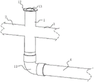
FIG. 1 is a schematic view of the overall structure of embodiment 1;
FIG. 2 is a half sectional view of the whole structure in embodiment 2;
FIG. 3 is a schematic view of the installation of the purge port;
FIG. 4 is a schematic view of a screen construction;
fig. 5 is a partially enlarged view of fig. 2 at a.
Description of the reference numerals: 1. a flow-stopping pipe; 11. a quarter bend fitting; 12. a cleaning port; 13. sealing the cover; 14. a clamping groove; 15. a guide block; 16. a capping slot; 2. a rain and sewage confluence pipe; 3. a rainwater drainage pipe; 4. a sewage discharge pipe; 5. a lifting rope; 51. a support bar; 52. a clamping block; 53. pricking by using a sharp needle; 55. filtering with a screen; 56. a guide groove; 6. a baffle plate assembly; 61. a sector plate; 62. a torsion spring; 63. an articulation member; 631. a hinged block; 632. a hinge plate; 633. a rotating shaft; 64. and (5) fixing the plate.
Detailed Description
The present application is described in further detail below with reference to figures 1-5.
Example 1:
the embodiment of the application discloses distribution system is carried in rain and sewage interception.
Referring to fig. 1, a rain and sewage intercepting and shunting system comprises an intercepting pipe 1 buried in the ground, wherein the side surface of the intercepting pipe 1 is connected with a rain and sewage converging pipe 2, a rain and sewage discharging pipe 3 and a sewage discharging pipe 4, the rear end of the rain and sewage discharging pipe 3 is connected with a rain water system, and the rear end of the sewage discharging pipe 4 is connected with a sewage system.
In the embodiment, the rain water discharge pipe 3 and the rain and sewage collecting flow pipe 2 are at the same horizontal height, and the rain water discharge pipe 3 and the rain and sewage collecting flow pipe 2 are respectively arranged on the side surface of the intercepting pipe 1; the rainwater drainage pipe 3 is positioned above the sewage drainage pipe 4, the right-angled elbow fitting 11 is installed at the bottom of the shutoff pipe 1, one end, far away from the shutoff pipe 1, of the right-angled elbow fitting 11 is connected with the sewage drainage pipe 4, and the right-angled elbow fitting 11 facilitates the combined water accumulated at the bottom of the shutoff pipe 1 to be drained into a sewage system at the rear end through the sewage drainage pipe 4.
Referring to fig. 1, the top of the intercepting pipe 1 is communicated with the ground, one end of the intercepting pipe 1, which is close to the ground, is provided with a cleaning opening 12 which is convenient for cleaning sundries in the intercepting pipe 1, the cleaning opening 12 is provided with a sealing cover groove 16, and a sealing cover 13 is installed in the sealing cover groove 16, so that the odor overflow of the sewage discharge pipe 4 can be reduced, and the cleanliness of the environment is improved.
The implementation principle of the embodiment 1 of the application is as follows:
when raining in the early stage/sunny day, the combined water enters the cut-off pipe 1 from the rain and sewage flow combining pipe 2, the combined water is sewage or rain and sewage mixed liquid with a large sewage component, the rain water discharging pipe 3 is positioned above the sewage discharging pipe 4, and the cut-off pipe 1 cuts the combined water from the sewage discharging pipe 4 at the bottom and sends the combined water to a sewage system at the rear end in a centralized manner; when the rainfall increases, confluence water gets into shutoff pipe 1 from rain and sewage confluence flow pipe 2, and sewage in the confluence aquatic deposits downwards under the action of gravity, concentrates the sewage system who sends to the rear end from the blow off water pipe 4 of bottom, and clear rainwater overflow gets into row's of rain water pipe 3 in the confluence water, sends the rainwater system of rear end through row's of rain water pipe 3, can reduce a large amount of rainwater and sewage and get into the sewage plant through sewage system simultaneously and cause the possibility of sewage plant overload operation. The pipe diameter of pipe 1 of damming compares with the pipe diameter of vatch basin, and the pipe diameter of pipe 1 of damming is less, and the narrow street lane of topography such as the ancient city district of being convenient for, old city district lays, is favorable to the distribution of rain and sewage operation of underground pipe network.
Example 2:
the embodiment of the application discloses rain and sewage intercepting and shunting system.
Referring to fig. 2 and 3, a rain and sewage intercepting and diverting system disclosed in the embodiment of the present application is different from that of embodiment 1 in that:
a supporting rod 51 is erected on the surface of the cleaning opening 12, clamping blocks 52 are respectively arranged at two ends of the supporting rod 51, a clamping groove 14 is formed in the cleaning opening 12, the two clamping blocks 52 are respectively clamped in the two clamping grooves 14, the shapes of the clamping blocks 52 are the same as those of the clamping grooves 14, the supporting rod 51 is positioned below the sealing cover 13, and the sealing cover 13 is not interfered to cover the cleaning opening 12 when the supporting rod 51 is clamped in the cleaning opening 12; the support rod 51 is connected with a lifting rope 5, the lifting rope 5 extends into the intercepting pipe 1, the surface of the lifting rope 5 is provided with a plurality of obliquely arranged spikes 53, all the spikes 53 are arranged along the lifting rope 5 in a staggered way, in the embodiment, the spikes 53 of the lifting rope 5 are partially positioned below the rain and sewage converging pipe 2.
Referring to fig. 2 and 4, a filter screen 55 is fixed at one end of the lifting rope 5 far from the ground, the outer diameter of the filter screen 55 is matched with the inner diameter of the cut-off pipe 1, a guide groove 56 is formed in the side edge of the filter screen 55, a guide block 15 is fixed on the inner wall of the cut-off pipe 1, the extension direction of the guide block 15 is arranged in the same direction as the water flow direction of the cut-off pipe 1, the guide block 15 is respectively arranged in a staggered manner with the rain and sewage combining pipe 2, the rain and sewage discharging pipe 3 and the sewage discharging pipe 4, the filter screen 55 is slidably mounted on the guide block 15 through the guide groove 56, the shape of the guide groove 56 is the same as that of the guide block 15, when the lifting rope 5 needs to be inserted into the cut-off pipe 1, the filter screen 55 slides on the guide block 15 through the guide groove 56, and the lifting rope 5 connected with the filter screen 55 simultaneously enters the cut-off pipe 1, so that the mounting efficiency of the lifting rope 5 is improved; the guide grooves 56 of the screen 55 are mounted on the guide block 15 to maintain the side walls of the screen 55 in abutment with the interior of the closure tube 1, reducing the possibility of the screen 55 becoming everted due to uneven forces on its surface.
In this embodiment, the number of the guide blocks 15 is two, and in other embodiments, the number of the guide blocks 15 may be three or four, but the guide blocks may function to guide the movement of the screen 55 in the cutoff pipe 1.
Referring to fig. 5, a baffle assembly 6 is arranged at one end of the rainwater drainage pipe 3 close to the cut-off pipe 1, the baffle assembly 6 comprises a fixed plate 64 and a plurality of sector plates 61, the fixed plate 64 is fixed on the inner wall of the rainwater drainage pipe 3, a hinge 63 is arranged between each sector plate 61 and the fixed plate 64, each hinge 63 comprises two hinge blocks 631, a rotating shaft 633 and a hinge plate 632, the two hinge blocks 631 are fixed on the fixed plate 64, the rotating shaft 633 is rotatably connected between the two hinge blocks 631, the hinge plate 632 is fixed on the sector plates 61, and the rotating shaft 633 penetrates through the hinge plate 632 and is rotatably arranged with the hinge plate 632; a torsion spring 62 is arranged between the hinge plate 632 and the hinge block 631, and all the sector plates 61 are in a mutually folded state in a normal state under the action of the torsion spring 62, so that the possibility that the odor of the intercepting pipe 1 overflows the outside from the rainwater drainage pipe 3 is reduced, and the environmental cleanliness is kept; in rainy weather, the fan-shaped plate 61 can rotate relative to the inside of the rainwater drainage pipe 3 under the impact of the combined flowing water of the fan-shaped plate 61, and the combined flowing water flows into the rainwater system from the rainwater drainage pipe 3.
The implementation principle of embodiment 2 of the present application is as follows:
when the combined water of the rain and sewage combined flow pipe 2 flows into the sewage discharge pipe 4 through the cut-off pipe 1, the sundries such as hair, vegetable leaves and the like in the combined water are hooked on the sharp spines 53, so that the possibility of environmental pollution caused by the blockage of the cut-off pipe 1 and the reverse flow of the sewage into the rain water discharge pipe 3 is reduced; and part of impurities which are not blocked by the barbs are blocked by the filter screen 55, so that the efficiency of treating the garbage in the intercepting pipe 1 is further improved, and the possibility of blocking the intercepting pipe 1 is reduced.
The above is a preferred embodiment of the present application, and the scope of protection of the present application is not limited by the above, so: equivalent changes in structure, shape and principle of the present application shall be covered by the protection scope of the present application.
Claims (8)
1. The utility model provides a rain and sewage cuts off reposition of redundant personnel system that goes which characterized in that: the intercepting pipe comprises an intercepting pipe (1) buried at the bottom of the ground, wherein the side surface of the intercepting pipe (1) is connected with a rain and sewage combining pipe (2), a rain water discharging pipe (3) and a sewage discharging pipe (4), the rear end of the sewage discharging pipe (4) is used for being connected with a sewage system, and the rear end of the rain water discharging pipe (3) is used for being connected with the rainwater system; the rainwater drainage pipe (3) is positioned above the sewage discharge pipe (4).
2. A rain and sewage interception and diversion system according to claim 1, characterized in that: the top end of the intercepting pipe (1) is communicated with the ground, one end, close to the ground, of the intercepting pipe (1) is provided with a cleaning opening (12), and a sealing cover (13) used for blocking odor overflowing of the intercepting pipe (1) is installed on the cleaning opening (12).
3. A rain and sewage intercepting and flow dividing system according to claim 2, wherein: a lifting rope (5) is arranged in the intercepting pipe (1), the lifting rope (5) is provided with a plurality of spikes (53), all the spikes (53) are arranged in a staggered mode along the extending direction of the lifting rope (5), and one end, close to the ground, of the lifting rope (5) is installed on the cleaning opening (12).
4. A rain and sewage intercepting and flow dividing system according to claim 3, wherein: one side that lifting rope (5) are close to ground is connected with bracing piece (51), joint piece (52) are installed respectively to the both ends of bracing piece (51), joint groove (14) have been seted up in scavenge port (12), joint piece (52) match the joint in joint groove (14).
5. A rain and sewage interception and diversion system according to claim 4, characterized in that: one end, far away from the ground, of the lifting rope (5) is provided with a filter screen (55), and the outer diameter of the filter screen (55) is matched with the inner diameter of the intercepting pipe (1).
6. A rain and sewage interception and diversion system according to claim 5, characterized in that: guide block (15) are installed to intercepting pipe (1) inner wall, guide block (15) extending direction sets up with intercepting pipe (1) extending direction syntropy, guide way (56) have been seted up to filter screen (55) side reason, filter screen (55) are through guide way (56) and guide block (15) installation of sliding.
7. A rain and sewage interception and diversion system according to claim 1, characterized in that: one end of the rainwater drainage pipe (3) close to the intercepting pipe (1) is provided with a baffle plate component (6) for blocking odor.
8. A rain and sewage intercepting and flow dividing system according to claim 7, wherein: the baffle plate assembly (6) comprises a plurality of sector plates (61) and a fixing plate (64), each sector plate (61) is hinged to the fixing plate (64), the fixing plate is fixed to the inner wall of the rainwater drainage pipe (3), a torsion spring (62) is installed at the hinged position of each sector plate (61) and the fixing plate (64), and all the sector plates (61) are mutually folded in due to the normal state of the torsion spring (62).
Priority Applications (1)
| Application Number | Priority Date | Filing Date | Title |
|---|---|---|---|
| CN202222133627.7U CN217811449U (en) | 2022-08-15 | 2022-08-15 | Rain and sewage intercepting and distributing system |
Applications Claiming Priority (1)
| Application Number | Priority Date | Filing Date | Title |
|---|---|---|---|
| CN202222133627.7U CN217811449U (en) | 2022-08-15 | 2022-08-15 | Rain and sewage intercepting and distributing system |
Publications (1)
| Publication Number | Publication Date |
|---|---|
| CN217811449U true CN217811449U (en) | 2022-11-15 |
Family
ID=83975496
Family Applications (1)
| Application Number | Title | Priority Date | Filing Date |
|---|---|---|---|
| CN202222133627.7U Active CN217811449U (en) | 2022-08-15 | 2022-08-15 | Rain and sewage intercepting and distributing system |
Country Status (1)
| Country | Link |
|---|---|
| CN (1) | CN217811449U (en) |
-
2022
- 2022-08-15 CN CN202222133627.7U patent/CN217811449U/en active Active
Similar Documents
| Publication | Publication Date | Title |
|---|---|---|
| CN208777112U (en) | Municipal drainage structure | |
| CN107747345B (en) | Surface pollution control system and method for combined drainage pipe network system | |
| CN209686564U (en) | A kind of small sponge urban ecology rainwater storage cell system | |
| CN108018936B (en) | A inlet for stom water for rainwater is retrieved and is recycled | |
| CN104863247A (en) | Sewer rain grate with filter function | |
| CN214461069U (en) | Municipal works hidden canal prevents stifled structure | |
| EP0924356A2 (en) | Structure for collecting rain water | |
| CN217811449U (en) | Rain and sewage intercepting and distributing system | |
| CN110644506A (en) | Side slope protection structure | |
| CN205329832U (en) | Take inlet for stom water of filter frame | |
| CN112538879B (en) | Highway sewage treatment structure and treatment method thereof | |
| CN213174049U (en) | Drainage system who possesses quick water conservancy diversion of rainwater | |
| CN206635911U (en) | Rain inlet structure with ponding function inside discharge subgrade and pavement | |
| WO1998022665A1 (en) | Rain water collection system and the use of a pertaining rain water diverting device | |
| CN107119781A (en) | A kind of automatic sewage collection system of urban flood control and drainage and method | |
| CN208685750U (en) | A kind of town road rainwater collection irrigation system | |
| CN112832353A (en) | Urban underground sewage pipeline laying system | |
| CN104047359B (en) | Jump weir formula cuts dirty inlet for stom water | |
| CN112962770A (en) | Rainwater overflow well | |
| CN209412696U (en) | A kind of highway bridge drainage system | |
| CN218814193U (en) | Diversion reconstruction system for village-town rain-sewage converging channel | |
| CN218970173U (en) | Outdoor non-point source pollution's rain and sewage distribution system | |
| CN212689073U (en) | Green energy-saving building rainwater collecting and processing system | |
| CN219297884U (en) | Road drainage structure | |
| CN219824795U (en) | Highway drainage structure |
Legal Events
| Date | Code | Title | Description |
|---|---|---|---|
| GR01 | Patent grant | ||
| GR01 | Patent grant |