CN217776312U - Auxiliary device for milling thin-wall shell parts - Google Patents
Auxiliary device for milling thin-wall shell parts Download PDFInfo
- Publication number
- CN217776312U CN217776312U CN202221971916.8U CN202221971916U CN217776312U CN 217776312 U CN217776312 U CN 217776312U CN 202221971916 U CN202221971916 U CN 202221971916U CN 217776312 U CN217776312 U CN 217776312U
- Authority
- CN
- China
- Prior art keywords
- supporting plate
- face
- plate
- upright post
- base
- Prior art date
- Legal status (The legal status is an assumption and is not a legal conclusion. Google has not performed a legal analysis and makes no representation as to the accuracy of the status listed.)
- Active
Links
Images


Abstract
The utility model belongs to the technical field of machining, concretely relates to thin wall class casing part mills auxiliary device. The device comprises a base, a stand column, a pressing plate, a surface A supporting plate, a fastening nut, a cushion block, a surface B supporting plate and a surface C supporting plate; the base is in a rectangular plate shape and serves as an installation platform of the device, and the left end and the right end of the base are provided with U-shaped grooves which are used for being fixedly connected with a milling platform of a milling machine through fastening bolts; the lower end of the upright post is fixedly connected with the base through threads or welding and the like, and the outer surface of the upright post is provided with threads for matching connection with a fastening nut; the pressing plate is of a U-shaped structure, an oval slotted hole is formed in the middle of the pressing plate, and the stand column penetrates through the oval slotted hole; the structure of the utility model is easy to manufacture, no complex structural member is provided, and the manufacturing cost is lower; the device principle is simple, and convenient operation can accomplish the milling process of a plurality of thin wall faces fast through the conversion of several backup pads, and convenient and fast has guaranteed the machining precision.
Description
Technical Field
The utility model belongs to the technical field of machining, concretely relates to thin wall class casing part mills auxiliary device.
Background
The utility model relates to a thin wall class casing part mills auxiliary device. The thin-wall shell parts are widely applied to various products in production and life, and also widely applied to the thin-wall shell parts in airplane assembly production. The part of this type, because the size is great, whole wallboard thickness is thinner, whole wallboard size 150 x 150mm above, the wall thickness is about 3mm, spatial structure. In the production of the parts, if a plate blank is adopted, the processing is very difficult, because more materials need to be removed, the generated participation stress or the deformation degree is more difficult to control, meanwhile, the thin-wall shell parts are generally limited by specification materials and the like of the cutter, and the cutter at a plurality of parts cannot process. For this reason, thin-walled housing parts, especially housing parts having a deep cavity structure, are usually made from a cast material, and then the allowance is removed by milling or the like.
The utility model relates to a as shown in figure 1 thin wall class casing part, the characteristics of this part are that there is dark chamber, and the cavity degree of depth reaches 149mm, and the wall thickness is 3mm, and cavity inner form side angle is R5, if need process in the cavity, then need use The length of the cutter is more than 149mm, but the cutter with the specification is difficult to find or high in cost, so that no allowance is left in the inner cavity when the blank is cast, and only a machining allowance is left on the outer molded surface and is removed by adopting a milling mode. When milling the outer allowance, it is found that, because the wall thickness is thin, if no auxiliary measures are taken, a large deformation occurs during processing, resulting in dimensional tolerance. For this purpose, special milling aids need to be designed to improve the deformation. Based on the above, the utility model discloses design the clamping device that mills that can be used for this thin wall casing part, aim at solving and mill the deformation problem.
SUMMERY OF THE UTILITY MODEL
The utility model aims at providing a thin wall class casing part mills auxiliary device to solve the above-mentioned problem that exists among the prior art.
The technical scheme of the utility model as follows:
the thin-wall shell part milling auxiliary device comprises a base, an upright post, a pressing plate, an A-surface supporting plate, a fastening nut, a cushion block, a B-surface supporting plate and a C-surface supporting plate.
The base is made of steel materials and is in a rectangular plate shape, the base is used as an installation platform of the device, and the left end and the right end of the base are provided with U-shaped grooves which are used for being fixedly connected with a milling platform of a milling machine through fastening bolts.
The stand support for steel material, the lower extreme passes through forms such as screw thread or welding and base fixed connection, the surface of stand is provided with the screw thread for be connected with fastening nut cooperation.
The pressing plate is of a U-shaped structure, an oval slot is formed in the middle of the pressing plate, and the stand column penetrates through the oval slot and can be adjusted in position through the oval slot; one end of the pressing plate is provided with a notch for avoiding interference with a part to be processed when enough pressing area is ensured.
The A-side supporting plate is of a T-shaped structure, an oval slotted hole is formed in the A-side supporting plate and used for enabling the stand column to penetrate through, and the oval slotted hole can guarantee that the relative positions of the rest stand columns can be adjusted during installation.
The cushion block is a hollow shell joint at the lower part, and a U-shaped groove is formed in one side surface of the lower end of the cushion block and used for avoiding the pressing position of the pressing plate so as to ensure that the pressing plate can press the part tightly; the upper end face of the cushion block is provided with a round hole for the upright post to pass through.
The B surface supporting plate is of a T-shaped structure, is provided with an elliptical slot hole for the upright post to pass through, and is different from the A surface supporting plate in that the supporting area of the B surface supporting plate is larger,
the whole C-face supporting plate is of a T-shaped structure, the left length and the right length of the bottom edge of the T-shaped support plate are different, an oval slot hole is formed in the support plate and used for allowing the stand column to penetrate through, and the supporting face of the support plate is provided with two U-shaped slots and used for avoiding a rib M of a vertical plate where the C-face is located, so that the supporting face is supported on the D-face.
Compared with the prior art, the beneficial effects of the utility model are that:
1. the device has the advantages of easy manufacture, no complex structural part and lower manufacture cost;
2. in addition, the device principle is simple, and convenient operation can accomplish the milling process of a plurality of thin wall faces through the conversion of several backup pads fast, and convenient and fast has guaranteed the machining precision.
Drawings
FIG. 1 is a schematic view of a structure of a part to be machined;
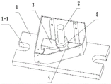
FIG. 2 is a schematic view of a milling fixture for face A;
fig. 3 is a schematic structural view of the platen 3;
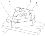
FIG. 4 is a schematic view of a milling fixture for face B;
fig. 5 is a front view and a left side view of the spacer 6;
FIG. 6 is an axial side view of the spacer 6;
FIG. 7 is a schematic view of a milling fixture for face C;
in the figure: 1-a base; 2-upright post; 3, pressing a plate; 4-a face support plate; 5-fastening a nut; 6, a cushion block; 7-B face support plate; 8-C face support plate.
Detailed Description
The following description will further explain embodiments of the present invention with reference to the drawings and technical solutions.
It should be understood that the appended drawings are not to scale, but are merely drawn with appropriate simplifications to illustrate various features of the basic principles of the invention. Specific design features of the invention disclosed herein, including, for example, specific dimensions, orientations, locations, and configurations, will be determined in part by the particular intended application and environment of use. In the several figures of the drawings, identical or equivalent components (elements) are referenced with the same reference numerals.
Example 1:
thin wall class casing part mills auxiliary device, includes base 1, stand 2, clamp plate 3, A face backup pad 4, fastening nut 5, cushion 6, B face backup pad 7 and C face backup pad 8.
The base 1 is made of steel materials and is in a rectangular plate shape, and serves as an installation platform of the device, and the left end and the right end of the installation platform are provided with U-shaped grooves which are used for being fixedly connected with a milling platform of a milling machine through fastening bolts.
The stand 2 support for steel material, the lower extreme passes through forms such as screw thread or welding and base 1 fixed connection, the surface of stand is provided with the screw thread for with fastening nut 5 cooperation be connected.
The pressing plate 3 is of a U-shaped structure, an elliptical slotted hole 3-1 is formed in the middle of the pressing plate, and the upright post 2 penetrates through the elliptical slotted hole 3-1 and can be adjusted in position through the elliptical slotted hole 3-1; one end of the pressing plate 3 is provided with a notch 3-2 for avoiding interference with a part to be processed when enough pressing area is ensured.
The A-side supporting plate 4 is of a T-shaped structure, and is provided with an oval slot hole for the upright post 2 to pass through, wherein the oval slot hole can ensure that the relative positions of the rest upright posts 2 can be adjusted during installation.
The cushion block 6 is a lower hollow shell joint, and one side surface of the lower end of the cushion block is provided with a U-shaped groove 6-1 which is used for avoiding the pressing position of the pressing plate 3 and ensuring that the pressing plate 3 can realize the pressing of the part; the upper end face of the cushion block 6 is provided with a round hole 6-2 for the upright post 2 to pass through.
The B face supporting plate 7 is of a T-shaped structure, is provided with an oval slot hole for the upright post 2 to pass through, is different from the A face supporting plate 4 in that the supporting area of the B face supporting plate 7 is larger,
the C-face supporting plate 8 is integrally of a T-shaped structure, the left length and the right length of the bottom edge of the T-shape are different, an oval slot hole is formed in the T-shaped supporting plate and used for enabling the stand column 2 to penetrate through, and the supporting face of the C-face supporting plate is provided with two U-shaped slots used for avoiding ribs M of a vertical plate where the C-face is located, so that the supporting face is supported on the D-face.
Example 2:
a thin-wall shell part milling auxiliary device comprises: the device comprises a base 1, a stand column 2, a pressing plate 3, a face A supporting plate 4, a fastening nut 5, a cushion block 6, a face B supporting plate 7 and a face C supporting plate 8. When the surfaces A, B and C are milled, the specific operation steps are as follows:
1, firstly, when the surface A is machined, parts are installed according to the sequence shown in figure 2, a pressure plate 3 is placed in a part cavity through an elliptical slotted hole 3-1, then an upright post penetrates through the elliptical slotted hole in a surface A supporting plate 4, the surface A supporting plate 4 is adjusted, a supporting surface is made to be attached to the inner side surface of a vertical plate where the surface A is located, a fastening nut 5 is adopted for screwing, the clamping of the parts and the supporting of the surface A are completed, and the surface A can be machined on a common milling machine.
And 2, after finishing the processing of the surface A, processing the surface B. The face A supporting plate 4 is dismounted, the cushion block 6 is placed according to the mode shown in the figure 4, the upright post 2 penetrates through the oval slotted hole of the face B supporting plate 7, the face B supporting plate 7 is adjusted, the supporting surface is tightly attached to the inner side surface of the vertical plate where the face B is located, the fastening nut 5 is adopted to tighten the supporting surface, the clamping of parts and the supporting of the face B are completed, and the face A can be machined on a common milling machine.
And 3, after finishing the processing of the surface B, processing the surface C. Lift B face backup pad 7 off, install C face backup pad 8 according to the mode as figure 7, installation and adjustment mode are on the same side, adopt fastening nut 5 to screw up, notice when installation C face backup pad 8, will guarantee that muscle M on the part is located the recess of holding surface for the holding surface top is on face D, guarantees the location effect, places because the unsettled deformation of large tracts of land.
Claims (3)
1. The milling auxiliary device for the thin-wall shell parts is characterized by comprising a base (1), an upright post (2), a pressing plate (3), an A-surface supporting plate (4), a fastening nut (5), a cushion block (6), a B-surface supporting plate (7) and a C-surface supporting plate (8);
the base (1) is in a rectangular plate shape and is used as an installation platform of the device, and the left end and the right end of the base are provided with U-shaped grooves which are used for being fixedly connected with a milling platform of a milling machine through fastening bolts;
the lower end of the upright post (2) is fixedly connected with the base (1) in the forms of threads, welding or the like, and the outer surface of the upright post (2) is provided with threads for being matched and connected with the fastening nut (5);
the pressing plate (3) is of a U-shaped structure, an elliptical slotted hole (3-1) is formed in the middle of the pressing plate, and the upright post (2) penetrates through the elliptical slotted hole (3-1) and can be adjusted in position through the elliptical slotted hole (3-1); one end of the pressure plate (3) is provided with a notch (3-2) for avoiding interference with a part to be processed when enough pressing area is ensured;
the A-side supporting plate (4) is of a T-shaped structure, an oval slot hole is formed in the A-side supporting plate and used for the upright post (2) to penetrate through, and the oval slot hole can ensure that the relative positions of the rest upright posts (2) can be adjusted during installation;
the cushion block (6) is a lower hollow shell joint, and one side surface of the lower end of the cushion block is provided with a U-shaped groove (6-1) for avoiding the pressing position of the pressing plate (3) and ensuring that the pressing plate (3) can realize the pressing of a part; the upper end face of the cushion block (6) is provided with a round hole (6-2) for the upright post (2) to pass through;
the B surface supporting plate (7) is of a T-shaped structure, is provided with an elliptical groove hole for the upright post (2) to pass through, and is different from the A surface supporting plate (4) in that the supporting area of the B surface supporting plate (7) is larger,
the C face supporting plate (8) is provided with an oval slot hole for the upright post (2) to pass through, and the supporting face of the C face supporting plate is provided with two U-shaped slots for avoiding a rib M of a vertical plate where the C face is located so as to enable the supporting face to be propped against the D face.
2. Milling aid for thin-walled shell-like parts according to claim 1, characterised in that the base (1) and the upright (2) are made of steel.
3. The milling aid for thin-walled shell-like parts according to claim 1 or 2, characterized in that the C-face support plate (8) is of a T-shaped overall configuration, with the T-shaped base side not being of uniform length from side to side.
Priority Applications (1)
| Application Number | Priority Date | Filing Date | Title |
|---|---|---|---|
| CN202221971916.8U CN217776312U (en) | 2022-07-29 | 2022-07-29 | Auxiliary device for milling thin-wall shell parts |
Applications Claiming Priority (1)
| Application Number | Priority Date | Filing Date | Title |
|---|---|---|---|
| CN202221971916.8U CN217776312U (en) | 2022-07-29 | 2022-07-29 | Auxiliary device for milling thin-wall shell parts |
Publications (1)
| Publication Number | Publication Date |
|---|---|
| CN217776312U true CN217776312U (en) | 2022-11-11 |
Family
ID=83942990
Family Applications (1)
| Application Number | Title | Priority Date | Filing Date |
|---|---|---|---|
| CN202221971916.8U Active CN217776312U (en) | 2022-07-29 | 2022-07-29 | Auxiliary device for milling thin-wall shell parts |
Country Status (1)
| Country | Link |
|---|---|
| CN (1) | CN217776312U (en) |
-
2022
- 2022-07-29 CN CN202221971916.8U patent/CN217776312U/en active Active
Similar Documents
| Publication | Publication Date | Title |
|---|---|---|
| CN102039532A (en) | Positioning method for machining workpiece and automatic clamp thereof | |
| CN102347668A (en) | Round stator punching and pressing mold structure with adjustable skewed slot angle | |
| CN113953859B (en) | Six point positioning tool for blade | |
| CN217776312U (en) | Auxiliary device for milling thin-wall shell parts | |
| CN107378572B (en) | Tool for machining stator plate of wind driven generator | |
| CN102284616B (en) | Adjustable Z-shaped offset bending mold | |
| CN102019475A (en) | Multifunctional angle pin discharging fixture | |
| CN202192154U (en) | Adjustable Z-shaped offset bending die | |
| CN209157739U (en) | A kind of elongate member milling fixture | |
| CN201900464U (en) | Automatic clamp for machining of workpiece | |
| CN2481449Y (en) | Clamp for internal grinding wing bearing seat | |
| CN209754556U (en) | Clamp with adjustable inclined plane | |
| CN212240040U (en) | Special milling fixture for weak-rigidity slice part | |
| CN209850238U (en) | Positioning assembly and tool | |
| CN216373474U (en) | Lower backing plate for die | |
| CN113305608A (en) | Clamping tool for milling certain cylindrical cross parts and batch application | |
| CN202668151U (en) | Clamp for machining drilling-milling combined surface of cylinder cover of engine | |
| CN206382664U (en) | A kind of tool for being used to process circular big cavity plate | |
| CN102205498A (en) | Clamp special for surface milling of multiple parts | |
| CN218363402U (en) | Sheet metal parts machining is with supplementary anchor clamps that support | |
| CN218518210U (en) | Mounting device for processing and positioning lower part structure of precombustion chamber | |
| CN220838968U (en) | Structural beam milling die | |
| CN218800648U (en) | Clamp for machining thin-wall part | |
| CN220480900U (en) | Clamping tool for machining casing | |
| CN213105694U (en) | Clamp for machining swash plate seat |
Legal Events
| Date | Code | Title | Description |
|---|---|---|---|
| GR01 | Patent grant | ||
| GR01 | Patent grant |