CN217710382U - Bridge cracking rear combination reinforcing apparatus - Google Patents
Bridge cracking rear combination reinforcing apparatus Download PDFInfo
- Publication number
- CN217710382U CN217710382U CN202221850032.7U CN202221850032U CN217710382U CN 217710382 U CN217710382 U CN 217710382U CN 202221850032 U CN202221850032 U CN 202221850032U CN 217710382 U CN217710382 U CN 217710382U
- Authority
- CN
- China
- Prior art keywords
- plate
- bridge
- carbon fiber
- prestressed carbon
- web
- Prior art date
- Legal status (The legal status is an assumption and is not a legal conclusion. Google has not performed a legal analysis and makes no representation as to the accuracy of the status listed.)
- Active
Links
Images


Landscapes
- Bridges Or Land Bridges (AREA)
Abstract
The utility model provides a bridge post-cracking combined reinforcing device, which belongs to the technical field of bridge engineering, and has the structure that prestressed carbon fiber plates are arranged on the bottom surface of a bridge web plate of a bridge cracking section, each prestressed carbon fiber plate is arranged in parallel, each prestressed carbon fiber plate is anchored and stretched on the bottom surface of the bridge web plate at the position through anchoring devices at the two ends in the length direction, and the prestressed carbon fiber plates are fixedly bonded with the bottom surface of the bridge web plate at the position through structural adhesive; two side surfaces of a bridge web plate at the bridge cracking section are respectively and fixedly connected with a ribbed steel plate; the plate body part of the ribbed steel plate is fixedly anchored on the side face of the bridge web plate through anchor bolts. The utility model discloses after the bridge produced the structural crack, make up at web and bottom plate and consolidate. The strength of the main beam is improved, the problem of rigidity reduction caused by web cracking is solved, the rigidity of the main beam is effectively improved, the crack development of the main beam is limited, and the purpose of reinforcing a bridge structure is achieved.
Description
Technical Field
The utility model belongs to the technical field of the bridge engineering technique and specifically relates to a bridge fracture back combination reinforcing apparatus.
Background
Generally, with the continuous increase of traffic volume, a large number of bridges built in early period generate structural cracks at key positions because the bearing capacity does not meet the requirement of vehicle load increase. Common reinforcing methods, such as a steel plate pasting reinforcing method, a prestress carbon fiber plate reinforcing method and the like, only reinforce a bridge bottom plate, improve the overall strength of the girder, neglect the problem of web cracking, and under the action of an external load, because of the stress concentration problem at the crack, the web crack is opened, the girder is not in a full-section stress state, and the rigidity is greatly reduced, so that the rigidity of the bridge is improved very limitedly after the conventional method is used for reinforcing, and the effect is not good.
SUMMERY OF THE UTILITY MODEL
The technical task of the utility model is to solve the not enough of prior art, provide a bridge fracture back combination reinforcing apparatus.
The technical scheme of the utility model is realized in the following way, the bridge cracking post-combination reinforcing device of the utility model comprises a prestressed carbon fiber plate, a ribbed steel plate and an anchor bolt,
a prestressed carbon fiber plate is arranged on the bottom surface of the bridge web plate at the bridge cracking section,
the prestressed carbon fiber plates are arranged in a strip shape, transverse spans on the bottom surface of the bridge web plate are uniformly distributed on the bottom surface of the bridge web plate at intervals, each prestressed carbon fiber plate is arranged in parallel, the longitudinal length of each prestressed carbon fiber plate is smaller than the length span of the whole bridge monomer of a cracking section, each prestressed carbon fiber plate is anchored and tensioned on the bottom surface of the bridge web plate through anchoring devices at two ends of the prestressed carbon fiber plate in the length direction, one end of each anchoring device at two ends is fixed to the prestressed carbon fiber plate, and the other end of each anchoring device at two ends is connected with the prestressed carbon fiber plate in a tensioning manner; the prestressed carbon fiber plate is fixedly bonded with the bottom surface of the web plate of the bridge through structural adhesive,
two side surfaces of a bridge web plate at the bridge cracking section are respectively and fixedly connected with a ribbed steel plate;
ribbed steel sheet is provided with plate body portion and rib portion, and plate body portion passes through crab-bolt fixed anchor and connects in roof beam body web side, and rib portion exposes in the external world, and the rib of rib portion moves towards the length direction parallel arrangement along the bridge web.
The anchoring device of the prestressed carbon fiber plate is provided with a fixed end anchorage device and a tensioning end anchorage device,
the fixed end anchorage and the tensioning end anchorage are respectively fixedly anchored on the bottom surface of the bridge web plate at two ends of a prestressed carbon fiber plate,
the fixed end of the prestressed carbon fiber plate is fixedly connected with a fixed head piece which is fixed on an anchorage device at the fixed end,
the tensioning end of the prestressed carbon fiber plate is fixedly connected with a tensioning head piece, the tensioning head piece is fixed on a floating tensioning piece, the floating tensioning piece is in sliding fit and is restrained on an anchorage device at the tensioning end through a rail, a tensioning jack is arranged between the anchorage device at the tensioning end and the floating tensioning piece, and the tensioning jack supports the floating tensioning piece through tension to tension the prestressed carbon fiber plate; and structural glue is coated between the prestressed carbon fiber plate in a tension state and the bottom surface of the bridge web for fixing and bonding.
The prestressed carbon fiber plates are uniformly arranged on the bottom surface of the bridge web at intervals of 40cm in transverse width span on the bottom surface of the bridge web.
The vertical height of the plate body part of the ribbed steel plate is less than or equal to the height of the central shaft of the bridge web,
the rib part of the ribbed steel plate is provided with n U-shaped ribs in the horizontal direction, the U-shaped opening parts of the U-shaped ribs are fixedly welded on the surface of the plate body part, and the number of the U-shaped ribs n is more than or equal to 3 and less than or equal to 10;
the inclination of the plate body part of the ribbed steel plate is consistent with the inclination of the side face of the bridge web plate;
the inner surface of the plate body part of the ribbed steel plate is fixedly bonded with the side face of the bridge web plate through steel adhesive.
The ribbed portion of ribbed steel sheet faces and is provided with one row of anchor bolt hole along the central line between two U type ribs, the configuration crab-bolt on each anchor bolt hole, be provided with the packing ring between the plate body portion of anchor bolt head and ribbed steel sheet, horizontal span interval distance between the anchor bolt hole sets up to 15cm, the surface of every anchor bolt hole contact packing ring is provided with annular fixed slot, the excircle diameter of annular fixed slot is greater than packing ring excircle diameter, the groove depth is less than the thickness of packing ring, packing ring thickness is the slope setting, its inclination and bridge web side inclination phase-match, the outer exposed surface that matches the back packing ring sets up to vertical face, the thinnest department of packing ring thickness sets up to 3mm, the internal surface that the packing ring laminated ribbed steel sheet plate body portion sets up to anti-skidding frosting.
The side face of the bridge web is provided with a pre-drilled hole corresponding to the position of the anchor bolt, the diameter of the pre-drilled hole is larger than that of the anchor bolt, after the ribbed steel plate is in place and the steel bonding glue is poured, the anchor bolt is screwed, and the redundant steel bonding glue between the side face of the bridge web and the plate body part of the ribbed steel plate is extruded to form close adhesion and fastening.
The surface of the prestressed carbon fiber plate is coated with protective paint.
Compared with the prior art, the utility model produced beneficial effect is:
the utility model discloses a bridge fracture back combination reinforcing apparatus is after the bridge produces structural crack, makes up at web and bottom plate and consolidates.
The utility model discloses replaced traditional single reinforcement method, both improved the intensity of girder, solved the rigidity reduction problem that the web fracture arouses again, effectively improved girder rigidity to restriction girder crack development reaches the purpose of consolidating the bridge structures.
Under the effect of external load, the stress state of the main beam is effectively guaranteed, and therefore the rigidity of the reinforced bridge is guaranteed to be improved.
The prestress carbon fiber plate reinforcing technology is an active reinforcing technology which can fully exert the strength of a carbon fiber material through prestress application, increase the strength and the rigidity of a structure, reduce the deflection deformation of the structure and reduce and close cracks.
The utility model discloses a bridge fracture back combination reinforcing apparatus reasonable in design, simple structure, safe and reliable, convenient to use, easy to maintain have fine using value widely.
Drawings
FIG. 1 is a schematic structural view of the combined reinforcing structure for a cracked bridge of the present invention;
FIG. 2 is a schematic structural diagram of a large sample of the combined structure adopted by the present invention;
FIG. 3 is a schematic structural diagram of a ribbed steel plate used in the present invention;
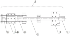
fig. 4 is a schematic structural diagram of an anchoring device used in the present invention.
The reference numerals in the drawings denote:
1. ribbed steel plate, 2, anchor bolt, 3, prestressed carbon fiber plate.
4. A bridge 5, a web 6, a web bottom 7 and a web side 7,
8. an anchoring device 9, a structural adhesive,
10. the plate body part 11, the rib part,
12. a fixed end anchorage device 13, a tension end anchorage device,
14. a fixed head piece, 15, a tension head piece,
16. a floating tension member 17, a tension jack,
18. u-shaped ribs, 19, adhesive steel glue,
20. anchor bolt hole 21, gasket 22, annular fixing groove 23, antiskid frosting surface,
24. pre-drilling, 25, and protective coating.
Detailed Description
The following detailed description is made on the bridge cracking rear combination reinforcing device of the present invention with reference to the accompanying drawings.
As shown in the attached drawings, the structure of the combined reinforcing device after the bridge cracking comprises a prestressed carbon fiber plate 3, a ribbed steel plate 1 and an anchor bolt 2,
a prestressed carbon fiber plate 3 is arranged on the bottom surface 6 of the bridge web plate at the bridge cracking section,
the prestressed carbon fiber plates 3 are arranged in a strip shape, transverse spans on the bottom surface 6 of the bridge web are uniformly distributed on the bottom surface 6 of the bridge web at intervals, each prestressed carbon fiber plate 3 is arranged in parallel, the longitudinal length of each prestressed carbon fiber plate is smaller than the length span of the whole bridge monomer of a crack section, each prestressed carbon fiber plate is anchored and tensioned on the bottom surface 6 of the bridge web through anchoring devices 8 at two ends of the prestressed carbon fiber plate in the length direction, one end of each anchoring device at two ends is fixed to the prestressed carbon fiber plate, and the other end of each anchoring device at two ends is connected with the prestressed carbon fiber plate in a tensioning manner; the prestressed carbon fiber plate is fixedly bonded with the bottom surface of the web plate of the bridge through structural adhesive 9,
two side surfaces of a bridge web plate at the bridge cracking section are respectively and fixedly connected with a ribbed steel plate;
ribbed steel sheet 1 is provided with plate body portion 10 and rib portion 11, and plate body portion 10 passes through crab-bolt 2 fixed anchor and connects at roof beam body web side 7, and rib portion 11 exposes in the external world, and the rib of rib portion moves towards the length direction parallel arrangement along the bridge web.
The anchoring device 8 of the prestressed carbon fiber plate is provided with a fixed end anchorage 12 and a tensioning end anchorage 13,
the fixed end anchorage 12 and the tensioning end anchorage 13 are respectively fixedly anchored on the bottom surface of the bridge web plate at two ends of a prestressed carbon fiber plate,
the fixed end of the prestressed carbon fiber plate 3 is fixedly connected with a fixed head piece 14, the fixed head piece 14 is fixed on a fixed end anchorage 12,
the tensioning end of the prestressed carbon fiber plate 3 is fixedly connected with a tensioning head piece 15, the tensioning head piece 15 is fixed on a floating tensioning piece 16, the floating tensioning piece 16 is in sliding fit and is restrained on an anchorage device 13 at the tensioning end through a rail, a tensioning jack 17 is arranged between the anchorage device 13 at the tensioning end and the floating tensioning piece 16, and the tensioning jack 17 supports the floating tensioning piece through tension so as to tension the prestressed carbon fiber plate; and structural glue 9 is coated between the prestressed carbon fiber plate in a tension state and the bottom surface of the bridge web for fixing and bonding.
The prestressed carbon fiber plates 3 are uniformly arranged on the bottom surface of the bridge web at intervals of 40cm in the transverse span on the bottom surface 6 of the bridge web.
The vertical height of the plate body part of the ribbed steel plate 1 is less than or equal to the height of the central shaft of the bridge web,
the rib part 11 of the ribbed steel plate 1 is provided with n U-shaped ribs 18 in the horizontal direction, U-shaped opening parts of the U-shaped ribs are fixedly welded on the surface of the plate body part, and the number of the U-shaped ribs n is more than or equal to 3;
the inclination of the plate body part of the ribbed steel plate is consistent with the inclination of the side face of the bridge web plate;
the inner surface of the plate body part of the ribbed steel plate is fixedly bonded with the side face 7 of the bridge web plate through steel adhesive 19.
Rib of ribbed steel sheet face between two U type ribs be provided with one row of anchor bolt hole 20 along the central line, configuration crab-bolt 2 on each anchor bolt hole, be provided with packing ring 21 between the plate body portion of anchor bolt head and ribbed steel sheet, horizontal span interval distance between the anchor bolt hole sets up to 15cm, the surface of every anchor bolt hole contact packing ring is provided with annular fixed slot 22, the excircle diameter of annular fixed slot is greater than packing ring excircle diameter, the groove depth is less than the thickness of packing ring, packing ring thickness is the slope setting, its inclination and bridge web side inclination phase-match, the outer exposed surface of matching back packing ring sets up to vertical face, the thinnest department of packing ring thickness sets up to 3mm, the internal surface of packing ring laminating ribbed steel sheet plate body sets up to anti-skidding frosting 23.
The position that corresponds the crab-bolt of bridge web side has seted up the predrilled hole 24, and the diameter of predrilled hole is greater than the crab-bolt diameter, waits that ribbed steel sheet takes one's place, pours into the viscose glue back, screws up the crab-bolt, extrudes the unnecessary viscose glue solution between bridge web side and ribbed steel sheet plate body portion, forms the close fastening of pasting.
The surface of the prestressed carbon fiber sheet is coated with a protective coating 25.
The utility model discloses a bridge fracture back combination reinforcing apparatus, wherein:
the prestressed carbon fiber plate strip-shaped carbon fiber plate is uniformly arranged on the bottom surface of a concrete beam at a transverse interval of 40cm, the longitudinal length of the prestressed carbon fiber plate strip-shaped carbon fiber plate is slightly smaller than the span of the bridge, the prestressed carbon fiber plate strip-shaped carbon fiber plate is fixed with a bridge web through two-end anchoring devices and structural glue, the single end of the prestressed carbon fiber plate strip-shaped carbon fiber plate is tensioned, the structural glue is firstly smeared on the surface of the carbon fiber plate in the construction sequence, and then the prestressed carbon fiber plate strip-shaped carbon fiber plate is installed in place and tensioned.
The ribbed steel plate is made of Q235B, the vertical height D0 is the height of a central shaft of the beam body and comprises n longitudinal U-shaped ribs, and the specific number is determined by calculation according to the height of a neutral shaft and the size of the U-shaped ribs; the inclination of the ribbed steel plate is consistent with that of the beam web; the longitudinal length of the ribbed steel plate is determined according to the crack distribution condition of the span-middle position of the web plate; the ribbed steel plate is fixed with the concrete beam body through steel adhesive.
A row of anchor bolt holes are formed between the two U-shaped ribs along the central line, the longitudinal spacing distance between the screw holes is 15cm, an annular fixing groove is formed in the outer surface, contacting the gasket, of each anchor bolt hole, the outer circle diameter of each annular fixing groove is larger than that of the corresponding gasket, the depth of each groove is smaller than the thickness of the corresponding gasket, the thickness of each gasket is adjusted according to the inclination of the ribbed steel plate, the thinnest part is 3mm, and the outer edge of each gasket is attached to the surface of the corresponding steel plate to form an anti-skid frosting surface;
the anchor bolt is a phi 12mm anchor bolt, a pre-drilling hole is formed in the corresponding position of the concrete beam body before the ribbed steel plate is adhered, the hole diameter is larger than the diameter of the anchor bolt, after the ribbed steel plate is in place and the steel adhesive glue is poured, the bolt is tightened, and the redundant steel adhesive glue is extruded out to achieve the close adhesion degree.
The utility model discloses a concrete implementation method does: the method comprises the steps of firstly installing a prestressed carbon fiber plate on the bottom surface of a bridge web plate and tensioning the prestressed carbon fiber plate to enable a bridge girder bottom plate and the bridge web plate to have certain pre-stress, then pasting a ribbed steel plate in a midspan cracking range, and tightly pressing and pasting the ribbed steel plate by using an anchor bolt.
The anchoring device adopts a prestress carbon fiber plate reinforcing system, and mainly comprises 6 main parts, namely a carbon fiber plate, an anchoring system (comprising a support, an anchor head, a tension rod and the like), carbon plate glue, a tensioning machine (comprising a jack, a tool baffle, a tool rod, a high-strength nut and the like), a batten and the like. The carbon fiber plate is prestressed and tensioned by a carbon fiber plate coated with carbon plate glue for a component needing to be reinforced, so that the component problem is repaired, the carbon fiber plate and the component form a unified whole, and the bearing capacity of the component is improved.
The carbon fiber has the characteristics of high strength, high modulus, high temperature resistance, corrosion resistance, fatigue resistance and the like. The tensile strength of the carbon fiber plate is 10 times or even more higher than that of the reinforcing steel bar. The prestressed carbon fiber plate technology is in a higher-capacity adaptation level before the carbon fiber plate bears high load weight, a certain strength is controlled in advance, and the high-strength performance of the carbon fiber plate is exerted more fully. In addition, the balance structure can enhance the rigidity of the structure, so that crack development is greatly relieved, the width of the crack is reduced, and the technical requirements of the highway bridge bearing capacity prestress carbon fiber plate on constructors are better improved. Careful handling is required to avoid damage to the carbon fibres.
Claims (7)
1. A combined reinforcing device after a bridge is cracked is characterized by comprising a prestressed carbon fiber plate, a ribbed steel plate and anchor bolts,
a prestressed carbon fiber plate is arranged on the bottom surface of the bridge web plate at the bridge cracking section,
the prestressed carbon fiber plates are arranged in a strip shape, transverse spans on the bottom surface of the bridge web plate are uniformly distributed on the bottom surface of the bridge web plate at intervals, each prestressed carbon fiber plate is arranged in parallel, the longitudinal length of each prestressed carbon fiber plate is smaller than the length span of the whole bridge monomer of a cracking section, each prestressed carbon fiber plate is anchored and tensioned on the bottom surface of the bridge web plate through anchoring devices at two ends of the prestressed carbon fiber plate in the length direction, one end of each anchoring device at two ends is fixed to the prestressed carbon fiber plate, and the other end of each anchoring device at two ends is connected with the prestressed carbon fiber plate in a tensioning manner; the prestressed carbon fiber plate is fixedly bonded with the bottom surface of the web plate of the bridge through structural adhesive,
two side surfaces of a bridge web plate at the bridge cracking section are respectively and fixedly connected with a ribbed steel plate;
ribbed steel sheet is provided with plate body portion and rib portion, and plate body portion passes through the fixed anchor of crab-bolt and connects in bridge web side, and rib portion exposes in the external world, and the rib of rib portion moves towards the length direction parallel arrangement along the bridge web.
2. The bridge post-cracking combination reinforcing device according to claim 1, characterized in that:
the anchoring device of the prestressed carbon fiber plate is provided with a fixed end anchorage device and a tensioning end anchorage device,
the fixed end anchorage device and the tensioning end anchorage device are respectively fixedly anchored on the bottom surface of the bridge web plate at two ends of a prestressed carbon fiber plate,
the fixed end of the prestressed carbon fiber plate is fixedly connected with a fixed head piece which is fixed on an anchorage device at the fixed end,
the tensioning end of the prestressed carbon fiber plate is fixedly connected with a tensioning head piece, the tensioning head piece is fixed on a floating tensioning piece, the floating tensioning piece is in sliding fit and is restrained on an anchorage device at the tensioning end through a rail, a tensioning jack is arranged between the anchorage device at the tensioning end and the floating tensioning piece, and the tensioning jack supports the floating tensioning piece through tension to tension the prestressed carbon fiber plate; and structural glue is coated between the prestressed carbon fiber plate in a tension state and the bottom surface of the bridge web for fixing and bonding.
3. The bridge post-cracking combination reinforcing device according to claim 1, characterized in that:
the transverse width span of the prestressed carbon fiber plates on the bottom surface of the bridge web is uniformly distributed on the bottom surface of the bridge web at intervals of 40 cm.
4. The bridge post-cracking combination reinforcing device according to claim 1, characterized in that:
the vertical height of the plate body part of the ribbed steel plate is less than or equal to the height of the central shaft of the bridge web,
the ribbed part of the ribbed steel plate is provided with n U-shaped ribs in the horizontal direction, the U-shaped opening parts of the U-shaped ribs are fixedly welded on the surface of the plate body part, and the number of the U-shaped ribs n is more than or equal to 3;
the inclination of the plate body part of the ribbed steel plate is consistent with the inclination of the side face of the bridge web plate;
the inner surface of the plate body part of the ribbed steel plate is fixedly bonded with the side face of the bridge web plate through steel adhesive.
5. The bridge post-cracking combination reinforcing device according to claim 4, characterized in that:
the rib portion of ribbed steel sheet faces between two U type ribs and is provided with one row of anchor bolt hole along the central line, the configuration crab-bolt on the anchor bolt hole of each department, be provided with the packing ring between the plate body portion of anchor bolt head and ribbed steel sheet, horizontal span interval distance between the anchor bolt hole sets up to 15cm, the surface of every anchor bolt hole contact packing ring is provided with annular fixed slot, the excircle diameter of annular fixed slot is greater than packing ring excircle diameter, annular fixed slot depth is less than the thickness of packing ring, packing ring thickness is the slope setting, its inclination and bridge web side inclination phase-match, the outer exposed surface of matching back packing ring sets up to vertical face, the thinnest department of packing ring thickness sets up to 3mm, the internal surface that the packing ring laminated ribbed steel sheet plate body portion sets up to anti-skidding frosting.
6. The bridge post-cracking combination reinforcing device according to claim 1, characterized in that:
the side face of the bridge web is provided with a pre-drilled hole corresponding to the position of the anchor bolt, the diameter of the pre-drilled hole is larger than that of the anchor bolt, after the ribbed steel plate is in place and the steel bonding glue is poured, the anchor bolt is screwed, and the redundant steel bonding glue between the side face of the bridge web and the plate body part of the ribbed steel plate is extruded to form close adhesion and fastening.
7. The bridge post-cracking combination reinforcing device according to claim 1, characterized in that:
the surface of the prestressed carbon fiber plate is coated with protective paint.
Priority Applications (1)
| Application Number | Priority Date | Filing Date | Title |
|---|---|---|---|
| CN202221850032.7U CN217710382U (en) | 2022-07-18 | 2022-07-18 | Bridge cracking rear combination reinforcing apparatus |
Applications Claiming Priority (1)
| Application Number | Priority Date | Filing Date | Title |
|---|---|---|---|
| CN202221850032.7U CN217710382U (en) | 2022-07-18 | 2022-07-18 | Bridge cracking rear combination reinforcing apparatus |
Publications (1)
| Publication Number | Publication Date |
|---|---|
| CN217710382U true CN217710382U (en) | 2022-11-01 |
Family
ID=83779918
Family Applications (1)
| Application Number | Title | Priority Date | Filing Date |
|---|---|---|---|
| CN202221850032.7U Active CN217710382U (en) | 2022-07-18 | 2022-07-18 | Bridge cracking rear combination reinforcing apparatus |
Country Status (1)
| Country | Link |
|---|---|
| CN (1) | CN217710382U (en) |
-
2022
- 2022-07-18 CN CN202221850032.7U patent/CN217710382U/en active Active
Similar Documents
| Publication | Publication Date | Title |
|---|---|---|
| CN203320978U (en) | Tensioning and anchoring device for prestressed carbon fiber sheet reinforced long-span concrete structure | |
| CN103321430B (en) | Pre-stressed carbon fiber sheet material is reinforced greatly across the construction method of concrete structure | |
| WO2017211107A1 (en) | Pre-stressed steel wire rope-based flexure- and shear-strengthening concrete t beam, and strengthening method thereof | |
| CN101074578B (en) | Special anchoros for wedged variable-corrugated clamped sheets | |
| CN109881842A (en) | A kind of FRP sheet material change chucking power wave-shaped splint anchor | |
| CN109025353A (en) | A kind of device and construction method of pre-stress FRP sheet material reinforcement of rc beam | |
| CN111622133A (en) | Bridge external pre-tightening force reinforcing system and mounting method thereof | |
| CN217710382U (en) | Bridge cracking rear combination reinforcing apparatus | |
| CN113338658A (en) | Reinforcing system and reinforcing method for T-shaped beam web | |
| CN110886185A (en) | Box girder with anchoring device and box girder bridge | |
| CN210239208U (en) | Anchoring structure for pasting carbon fiber plate at bottom of reinforced concrete beam | |
| CN212406216U (en) | Fiber cloth prestress applying device | |
| CN215925725U (en) | Large-tonnage prestressing force carbon fiber plate anchor | |
| CN210976324U (en) | Prestressed composite-ultra-high performance concrete composite beam | |
| CN208183557U (en) | A kind of prestressed fiber cloth reinforced device | |
| CN111622136A (en) | Prestressed carbon fiber flexible material tensioning and anchoring device and construction method thereof | |
| CN219218699U (en) | Prestressed carbon fiber plate anchoring structure for bridge | |
| CN109898883A (en) | A kind of anchorage technology measure of armored concrete beam bottom sticking carbon fiber plate | |
| CN219080117U (en) | Reinforced structure of T-beam-attached steel plate conversion box beam | |
| CN212865569U (en) | Box girder bottom plate reinforced structure, box girder and box girder bridge | |
| CN115595901B (en) | Method for reinforcing arch springing of upper bearing arch bridge based on cable structure | |
| CN217841004U (en) | Transverse deformation resetting and carbon fiber sheet prestress reinforcing system for damaged beam | |
| CN220789470U (en) | Reinforcing device for reinforced concrete T-shaped beam bridge | |
| CN211948017U (en) | Bridge crack repairing and fixing structure | |
| CN214220647U (en) | Flat friction type anchorage device applied to tensioning of prestressed FRP (fiber reinforced plastic) grids |
Legal Events
| Date | Code | Title | Description |
|---|---|---|---|
| GR01 | Patent grant | ||
| GR01 | Patent grant |