CN217649192U - Holding posture correcting pen - Google Patents
Holding posture correcting pen Download PDFInfo
- Publication number
- CN217649192U CN217649192U CN202221624759.3U CN202221624759U CN217649192U CN 217649192 U CN217649192 U CN 217649192U CN 202221624759 U CN202221624759 U CN 202221624759U CN 217649192 U CN217649192 U CN 217649192U
- Authority
- CN
- China
- Prior art keywords
- pen
- sleeve
- groove
- pen point
- finger
- Prior art date
- Legal status (The legal status is an assumption and is not a legal conclusion. Google has not performed a legal analysis and makes no representation as to the accuracy of the status listed.)
- Active
Links
Images


Abstract
The utility model provides a holding posture correction pen, it includes: the pen holder is formed by rotationally butting a pen point sleeve and a pen tube, a rotational connection point of the pen holder is positioned in the middle of the finger groove, and each finger groove is divided into a first groove and a second groove which rotate relatively; the pen core is axially arranged in the pen holder and comprises a pen point and a core rod; the sliding column is sleeved outside the core rod, a first rotating part is arranged on the outer surface of the sliding column, a second rotating part is arranged on the inner side wall of the pen point sleeve, and the second rotating part is in spiral sliding fit with the first rotating part so that the pen point extends out of or retracts into the pen point sleeve; and rotating the pen point sleeve until the three first grooves and the three second grooves are in one-to-one butt joint to form complete finger grooves, and enabling the pen point to extend out of the pen point sleeve. The utility model has the advantages of being simple in structure and convenient in operation, during the use, rotatory nib cover makes the nib stretch out to hold in the finger recess that corresponds with the finger and just can normally write.
Description
Technical Field
The utility model belongs to the technical field of learning tools, especially, relate to a holding posture correction pen.
Background
The pen is used as an indispensable writing tool in daily life and work, the correctness of the pen holding posture is very important when the pen is used, and particularly the pen holding posture is more important for children who do not form the pen holding habit, the wrong pen holding posture not only influences the writing speed and the normative performance, but also induces the phenomena of myopia, strabismus, spinal curvature and the like, and in order to solve the problem, various pen holding posture correcting pens are generated.
Most pen holding posture correction pens in the existing market are realized by adding pen caps or additionally arranging three finger arc-shaped surfaces at pen holding positions, the pen caps occupy a large area, and especially primary school students can write with the original pens under the condition that parents do not supervise, and the posture correction cannot be well performed. The mode of additionally arranging the finger arc-shaped surface has limited effect, no mandatory measures are provided, the writing can be carried out at the position where the finger arc-shaped surface is not pressed, and the aim of posture correction can not be well achieved. In order to solve the problem, the utility model with the publication number CN202847211U discloses a pen for correcting the holding posture, which adopts three finger-shaped grooves to correct the holding posture, and through the cooperation of the central processing unit, the pressure sensor and the telescopic mechanism, when the thumb, the middle finger and the forefinger of the user respectively press the corresponding finger-shaped grooves (namely the pen holding posture is correct), the central processing unit controls the telescopic mechanism to drive the pen core to extend, thereby writing normally; on the contrary, when the thumb, the middle finger and the index finger of the user do not press the corresponding finger-shaped grooves (namely the pen holding posture is incorrect), the central processing unit controls the telescopic mechanism to shrink the pen core, so that the correction purpose is achieved. The holding posture correcting pen can force a user to use a correct holding posture for writing, but has the problems of complex structure and higher cost, electronic elements in the pen are greatly influenced by factors such as environment and the like, and the service life of the pen is shorter.
SUMMERY OF THE UTILITY MODEL
The utility model provides an above-mentioned technical problem, provide a hold appearance and correct pen, should hold appearance and correct a simple structure, convenient to use, user only need use the exact posture to hold when setting up the finger recess, the nib could stretch out from the front end of nib cover, normally writes, does not need other supplementary, and the cost is lower and durable, and life is longer relatively.
In order to achieve the above object, the utility model discloses a technical scheme be:
provided is a holding posture correcting pen, which comprises:
the pen holder is formed by rotationally butting a pen point sleeve and a pen tube, a rotational connection point of the pen holder is positioned in the middle of the finger groove, and each finger groove is divided into a first groove and a second groove which rotate relatively;
the refill is axially arranged in the pen holder and comprises a pen point and a core rod which are coaxially arranged;
the sliding column is sleeved outside the core rod, a first rotating part is arranged on the outer surface of the sliding column, a second rotating part is arranged on the inner side wall of the pen point sleeve, and the second rotating part is in spiral sliding fit with the first rotating part, so that the pen point extends out of or retracts into the front end part of the pen point sleeve;
when writing, the pen point sleeve is rotated until the three first grooves and the three second grooves are in one-to-one butt joint to form complete finger grooves, and the pen point extends out of the pen point sleeve.
According to the holding posture correction pen provided by the technical scheme, the pen point sleeve is rotationally connected with the pen tube to divide the complete finger groove into two parts. When the pen point sleeve is used, the pen point sleeve is rotated until the three first grooves and the three second grooves are in one-to-one butt joint to form complete finger grooves, the pen point extends out of the pen point sleeve, and when the thumb, the middle finger and the forefinger of a user respectively press the corresponding finger grooves, namely the pen holding posture is correct, the pressing force of the pen point sleeve prevents the pen point sleeve and the pen tube from rotating relatively, so that the pen core is kept in an extending state and cannot retract, and normal writing can be performed. When not using, but the nib cover is rotated, under second rotating part and first rotating part spiral sliding fit, retracts the refill in the nib cover, avoids appearing pricking the phenomenon of bad nib to a certain extent.
In some other embodiments of the present application, the holding posture correcting pen further includes an elastic element sleeved outside the pen point, one end of the elastic element abuts against the inner side of the front end of the pen point sleeve, the other end of the elastic element abuts against the core rod, and a restoring force of the elastic element pushes against the core rod to drive the pen point to retract into the pen point sleeve; after the holding posture correction pen finishes writing and loosens the hand, the elastic element is arranged to enable the pen point to automatically retract into the pen point sleeve, and the restoring force of the elastic element enables the pen point to keep in a retracting state.
In some other embodiments of the present application, a limiting portion is disposed on an outer peripheral wall of the core rod connected to one end of the pen tip, one side of the limiting portion abuts against one end of the sliding column, and the other side of the limiting portion abuts against one end of the elastic element; through setting up spacing portion for the slip post can push against the refill motion and stretch out, makes the restoring force of spring can push against the refill motion and retract equally, and is simple and convenient.
In other embodiments of the present application, the elastic element is a return spring, and the return spring provides an elastic force required by the sliding column to return.
In some other embodiments of the present application, the first rotating portion is an external threaded bar, and the second rotating portion is a notch spirally engaged with the external threaded bar, wherein the notch is connected to the external threaded bar and slides along an extending direction of the external threaded bar.
In some other embodiments of the present application, the holding posture correcting pen further includes a square block sleeved outside the core bar, the square block is fixedly disposed at one end of the sliding column away from the pen tip, a flange is disposed on an inner peripheral wall of the pen tube, and the flange surrounds to form a square hole matched with the square block; the square hole is used for restricting the sliding column from radially rotating in cooperation with the square block, so that the sliding column can only move along the axial direction.
In other embodiments of this application, the sliding column with square piece integration is connected, and the integration connected mode, simple structure, convenient processing.
In other embodiments of the present application, an annular flange is disposed on an inner peripheral wall of the nib cover, the second rotating portion is disposed on the annular flange, and the annular flange is matched with the shape of the sliding column to facilitate connection and assembly of the sliding column.
In some other embodiments of the present application, a cylindrical clamping portion is disposed at one end of the pen barrel, one of an annular protrusion and an annular groove is disposed on an outer circumferential wall of the cylindrical clamping portion, the inner circumferential wall of one end of the pen nib sleeve connected to the pen barrel is provided with the other of the annular protrusion and the annular groove, the cylindrical clamping portion is sleeved in the pen nib sleeve, and the annular protrusion is embedded in the annular groove; the pen point sleeve is rotatably connected with the pen tube through the matching of the annular protrusion and the annular groove.
In other embodiments of the present application, the outer diameter of the pen tube is 13mm, and the length of the holding posture correction pen is 140mm, so that the holding posture correction pen formed by the size is most suitable for being used by primary and secondary school students.
Other features and advantages of the present invention will become more apparent from the following detailed description of the invention when read in conjunction with the accompanying drawings.
Drawings
FIG. 1 is a schematic structural view of the pen point of the holding posture correction pen according to the present invention in an extended state;
FIG. 2 is a schematic view of the pen point retracting state of the holding posture correction pen of the present invention;
FIG. 3 is a cross-sectional view of the pen point retracted state of the holding posture correction pen of the present invention;
FIG. 4 is a sectional view of a structure of a pen nib cover according to an embodiment of the present invention;
FIG. 5 is a sectional view of the pen barrel according to the present invention;
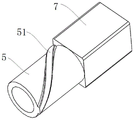
fig. 6 is a schematic structural view of the sliding column of the present invention.
In the above figures: a holding posture correction pen 100; a nib cover 1; a second rotating section 11; an annular flange 12; a pen tube 2; a flange 21; a cylindrical snap-in section 22; a square hole 22; a finger groove 3; a first groove 31; a second groove 32; a pen core 4; a pen tip 41; a core bar 42; a stopper portion 43; a sliding post 5; a first rotating part 51; an elastic element 6; a square block 7; an annular projection 8; an annular groove 9.
Detailed Description
The present invention is specifically described below by way of exemplary embodiments. It should be understood, however, that elements, structures and features of one embodiment may be beneficially incorporated in other embodiments without further recitation.
In the description of the present invention, it should be noted that the terms "inside", "outside", "upper", "lower", "front", "rear", and the like indicate orientations or positional relationships based on positional relationships shown in the drawings, and are only for convenience of description and simplification of description, but do not indicate or imply that the device or element referred to must have a specific orientation, be constructed and operated in a specific orientation, and thus, should not be construed as limiting the present invention.
The terms "first", "second" and "third" are used for descriptive purposes only and are not to be construed as indicating or implying relative importance or implicitly indicating the number of technical features indicated. Thus, features defined as "first", "second", "third" may explicitly or implicitly include one or more of the features.
In order to better understand the technical solutions, the technical solutions are described in detail below with reference to the accompanying drawings and specific embodiments.
Referring to fig. 1 to 6, in an exemplary embodiment of a holding posture correction pen 100 of the present invention, the holding posture correction pen 100 includes a pen holder, a pen core 4, and a sliding column 5.
Specifically, three finger grooves 3 corresponding to correct pen holding postures are arranged on the outer surface of the pen holder, the pen holder is formed by rotatably butting the pen point sleeve 1 and the pen tube 2, the rotating connection point of the pen point sleeve is positioned in the middle of the finger grooves 3, and each finger groove 3 is divided into a first groove 31 and a second groove 32 which rotate relatively.
The cartridge 4 is axially arranged in the pen holder, and the cartridge 4 comprises a pen tip 41 and a core rod 42 which are coaxially arranged.
The outside of core bar 42 is located to the slip post 5 cover, and the surface of slip post 5 is provided with first rotating part 51, and the inside wall of nib cover 1 is provided with second rotating part 11, and second rotating part 11 and the spiral sliding fit of first rotating part 51 for nib 41 stretches out or retracts from the front end of nib cover 1.
During writing, the three first grooves 31 and the three second grooves 32 of the pen tip sleeve 1 are in one-to-one butt joint to form the complete finger grooves 3, and the pen tip 41 extends out of the pen tip sleeve 1. In this embodiment, the first groove 31 is disposed on the pen nib cover 1, and the second groove 32 is disposed on the pen barrel 2.
More specifically, the holding posture correction pen 100 provided by the embodiment has a simple structure, is convenient to use, and is easy to popularize. The penholder is provided with three finger grooves 3 corresponding to the correct pen holding posture, and the correct pen holding posture can be kept by respectively pinching the thumb, the middle finger and the forefinger of a user into the corresponding finger grooves during writing. The pen point sleeve 1 is rotationally connected with the pen tube 2 to divide the three complete finger grooves 3 into two parts. When the pen is used, the pen point sleeve 1 is rotated until the three first grooves 31 and the three second grooves 32 are in one-to-one butt joint to form the complete finger grooves 3, the pen point 41 extends out of the pen point sleeve 1, and when the thumb, the middle finger and the forefinger of a user respectively press the corresponding finger grooves 3, namely the pen holding posture is correct, the pressing force of the pen point sleeve 1 and the pen tube 2 is prevented from rotating relatively by the pressing force of the pen point sleeve 1, so that the pen core 4 is kept in the extending state and cannot retract, and normal writing can be performed. When the pen nib holder is not used, the pen nib 41 can be retracted into the pen nib holder 1 by rotating the pen nib holder 1 and spirally sliding matching the second rotating portion 11 and the first rotating portion 51, so that the phenomenon that the pen nib 41 is damaged by pricking is avoided to a certain extent.
The pen 100 for correcting the grip posture provided by the embodiment can forcibly use the correct grip posture to write to a certain extent. Specifically, if the nib sleeve 1 is not rotated in place and the pen core 4 cannot be completely extended, normal writing cannot be performed, and when the holding posture is incorrect, a large force is required to prevent the nib sleeve 1 and the pen tube 2 from rotating relatively, and normal and comfortable writing cannot be performed.
Further, referring to fig. 4, an annular flange 12 is disposed on the inner peripheral wall of the nib cover 1, the second rotating portion 11 is disposed on the annular flange 12, and the annular flange 12 is matched with the shape of the sliding column 5 to facilitate the connection and assembly of the sliding column 5.
Preferably, referring to fig. 4 and 6, in the present embodiment, the first rotating portion 51 is a male screw thread strip, and the second rotating portion 11 is a notch spirally engaged with the male screw thread strip, the notch being connected with the male screw thread strip and sliding along the extending direction of the male screw thread strip. Part external screw thread strip is located the notch, and the notch plays the effect of spiral business turn over with the cooperation of external screw thread strip. When the holding posture correction pen 100 is used, the rotating pen tip sleeve 1 drives the notch to slide along the external thread strip, so that the sliding column 5 where the external thread strip is located makes a spiral feeding motion towards the pen tip 41, and the pen tip 41 is pushed to extend out from the front end part of the pen tip sleeve 1. It should be noted that the present application does not limit the rotation direction of the pen tip cover 1, i.e. the rotation direction of the external thread strip, and the first rotation portion 51 and the second rotation portion 11 may be other components that are spirally engaged, for example, in other embodiments, the first rotation portion 51 may be a thread groove, and the second rotation portion 11 may be a projection engaged therewith.
Referring to fig. 3, the holding posture correcting pen 100 further includes an elastic element 6 sleeved outside the pen point 41, one end of the elastic element 6 abuts against the inner side of the front end of the pen tip sleeve 1, the other end abuts against the core rod 42, and the restoring force of the elastic element 6 pushes against the core rod 42 to drive the pen point 41 to retract into the pen tip sleeve 1; further, a stopper 43 is provided on the outer peripheral wall of the core pin 42 connected to one end of the pen tip 41, one side of the stopper 43 abuts on one end of the slide column 5, and the other side abuts on one end of the elastic member 6.
The grip posture correction pen 100 according to the present embodiment automatically retracts the pen tip 41 into the pen nib cover 1 by the restoring force of the elastic member 6 after the writing is completed and the hand is released, and maintains the retracted state of the pen tip 41. Meanwhile, the restoring force of the elastic element 6 ensures that when the holding posture is incorrect, a larger pressing force is needed to prevent the pen point sleeve 1 and the pen tube 2 from rotating relatively, so that a user can write harder in the posture, normal writing is not facilitated, and the function of forcibly using the correct posture to write is further realized. The limiting part 43 is arranged, so that the sliding column 5 and the elastic element 6 can be abutted to the refill 4 conveniently, the refill 4 can be driven or pushed to move, and the pen holder is simple and convenient. Preferably, the elastic element 6 is a return spring, which provides the elastic force required for the return of the sliding post 5.
Further, referring to fig. 3 and 6, the holding posture correction pen 100 further includes a square block 7 sleeved outside the core rod 42, the square block 7 is fixedly disposed at one end of the sliding column 5 away from the pen tip 41, a flange 21 is disposed on the inner peripheral wall of the pen tube 2, and the flange 21 surrounds and forms a square hole 22 matched with the square block 7. In this embodiment, the square hole 22 and the square block 7 cooperate to restrict the sliding column 5 from rotating radially, so that the sliding column 5 can only move in the axial direction, and the pen tip 41 can be extended or retracted. Preferably, in this embodiment, the sliding column 5 is integrally connected with the square block 7, and this connection mode is simple in structure and convenient to process.
Referring to fig. 4 and 5, a cylindrical clamping portion 22 is arranged at one end of the pen barrel 2, one of the annular protrusion 8 and the annular groove 9 is arranged on the outer circumferential wall of the cylindrical clamping portion 22, the other one of the annular protrusion 8 and the annular groove 9 is arranged on the inner circumferential wall of the one end of the pen tip cover 1 connected with the pen barrel 2, and the cylindrical clamping portion 22 is sleeved in the pen tip cover 1 and the annular protrusion 8 is embedded in the annular groove 9. The annular protrusion 8 is matched with the annular groove 9, so that the pen point sleeve 1 is rotationally connected with the pen tube 2. Specifically, in the present embodiment, the outer diameter of the end of the nib cover 1 connected to the barrel 2 is the same as the outer diameter of the barrel 2, and the outer diameter of the cylindrical engaging portion 22 is smaller than the outer diameter of the barrel 2. Illustratively, in the present embodiment, the outer peripheral wall of the cylindrical clamping portion 22 is provided with an annular groove 9, and the inner peripheral wall of the nib cover 1 is provided with an annular protrusion 8.
Referring to fig. 1, in order to make the size of the pen 100 more suitable for the middle and primary school students, in the present embodiment, the length L of the pen 100 is preferably 140mm, and the outer diameter d of the pen tube 2 is preferably 13mm. Illustratively, the pen tip cover 1 has a length dimension L1 of 26mm.
The utility model provides a pen 100 for correcting holding posture, rotating the pen point sleeve 1 to make the pen point 41 stretch out from the pen point sleeve 1, when the holding posture is correct, normal writing can be carried out, when the holding posture is not right, the pen point 41 can not stretch out completely or even retract into the pen point sleeve 1, normal and comfortable writing can not be carried out, and the pen holding posture can be corrected conveniently; the holding posture correction pen 100 is reasonable in structure, comfortable, convenient, easy to use and suitable for wide popularization.
The above description is only a preferred embodiment of the present invention, and is not intended to limit the present invention in other forms, and any person skilled in the art may apply the equivalent embodiments modified or modified by the above technical contents disclosed as equivalent variations to other fields, but any simple modifications, equivalent changes and modifications made to the above embodiments according to the technical spirit of the present invention will still fall within the protection scope of the technical solution of the present invention.
Claims (10)
1. A holding posture correcting pen is characterized by comprising:
the pen holder is formed by rotationally butting a pen point sleeve and a pen tube, a rotational connection point of the pen holder is positioned in the middle of the finger groove, and each finger groove is divided into a first groove and a second groove which rotate relatively;
the refill is axially arranged in the pen holder and comprises a pen point and a core rod which are coaxially arranged;
the sliding column is sleeved outside the core rod, a first rotating part is arranged on the outer surface of the sliding column, a second rotating part is arranged on the inner side wall of the pen point sleeve, and the second rotating part is in spiral sliding fit with the first rotating part, so that the pen point extends out of or retracts into the front end part of the pen point sleeve;
when writing, the pen point sleeve is rotated until the three first grooves and the three second grooves are in one-to-one butt joint to form complete finger grooves, and the pen point extends out of the pen point sleeve.
2. The pen of claim 1, further comprising an elastic element sleeved outside the pen tip, wherein one end of the elastic element abuts against the inner side of the front end of the pen tip sleeve, the other end of the elastic element abuts against the core rod, and the restoring force of the elastic element pushes the core rod to drive the pen tip to retract into the pen tip sleeve.
3. The pen as claimed in claim 2, wherein a stopper is provided on an outer peripheral wall of the core rod connected to one end of the nib, one side of the stopper abuts against one end of the sliding column, and the other side abuts against one end of the elastic member.
4. The pen of claim 2, wherein the elastic element is a return spring.
5. The pen of claim 1, wherein the first rotating portion is an externally threaded strip, the second rotating portion is a slot spirally engaged with the externally threaded strip, and the slot is connected with the externally threaded strip and slides along an extending direction of the externally threaded strip.
6. The pen of claim 1, further comprising a square block sleeved outside the core rod, wherein the square block is fixedly disposed at an end of the sliding column away from the pen tip, and a flange is disposed on an inner peripheral wall of the pen tube and surrounds a square hole matching the square block.
7. The pen of claim 6, wherein the sliding post is integrally connected to the square block.
8. The pen as claimed in claim 1, wherein an annular flange is provided on an inner peripheral wall of the nib cover, and the second rotating portion is provided on the annular flange.
9. The holding posture correction pen according to claim 1, wherein one end of the pen barrel is provided with a cylindrical clamping portion, the outer peripheral wall of the cylindrical clamping portion is provided with one of an annular protrusion and an annular groove, the inner peripheral wall of the pen nib sleeve connected with one end of the pen barrel is provided with the other one of the annular protrusion and the annular groove, the cylindrical clamping portion is sleeved in the pen nib sleeve, and the annular protrusion is embedded in the annular groove.
10. The pen as claimed in claim 1, wherein the outer diameter of the pen tube is 13mm, and the length of the pen is 140mm.
Priority Applications (1)
| Application Number | Priority Date | Filing Date | Title |
|---|---|---|---|
| CN202221624759.3U CN217649192U (en) | 2022-06-27 | 2022-06-27 | Holding posture correcting pen |
Applications Claiming Priority (1)
| Application Number | Priority Date | Filing Date | Title |
|---|---|---|---|
| CN202221624759.3U CN217649192U (en) | 2022-06-27 | 2022-06-27 | Holding posture correcting pen |
Publications (1)
| Publication Number | Publication Date |
|---|---|
| CN217649192U true CN217649192U (en) | 2022-10-25 |
Family
ID=83685273
Family Applications (1)
| Application Number | Title | Priority Date | Filing Date |
|---|---|---|---|
| CN202221624759.3U Active CN217649192U (en) | 2022-06-27 | 2022-06-27 | Holding posture correcting pen |
Country Status (1)
| Country | Link |
|---|---|
| CN (1) | CN217649192U (en) |
-
2022
- 2022-06-27 CN CN202221624759.3U patent/CN217649192U/en active Active
Similar Documents
| Publication | Publication Date | Title |
|---|---|---|
| WO2020211623A1 (en) | Torsion position clamping pen | |
| CN100469595C (en) | Rotary advancement-type writing implement | |
| TW490400B (en) | Variable contour grip | |
| CN110303801B (en) | Telescopic pen | |
| US9610797B2 (en) | Ergonomic and versatile writing instrument | |
| CN110370842B (en) | Press flexible pen | |
| US6517271B1 (en) | Double-chuck mechanical pencil | |
| CN110356144B (en) | Bidirectional pressing telescopic pen | |
| CN110395067B (en) | Magnetic rotary telescopic pen | |
| US5555602A (en) | Eraser assembly | |
| JPS6056596A (en) | Writing utensil having projecting and pulling-in mechanism | |
| CN217649192U (en) | Holding posture correcting pen | |
| CN210363090U (en) | Hand-held telescopic pen | |
| CA2795230C (en) | Improved expandable writing instrument | |
| CN110303800B (en) | Compression pen with replaceable refill | |
| CN103660698B (en) | Writing instrument with simplified assembly | |
| US20020021290A1 (en) | Input pen | |
| EP0863023B1 (en) | Double-chuck mechanical pencil | |
| JPH0761758B2 (en) | Rotating device for writing instruments | |
| CN209920834U (en) | Writing tool | |
| WO2005100045A1 (en) | Front-knock type ballpen | |
| JPH0432315Y2 (en) | ||
| JPH0632397Y2 (en) | Compound writing instrument | |
| JPS5852149Y2 (en) | Shape pencil | |
| JPH061831Y2 (en) | mechanical pencil |
Legal Events
| Date | Code | Title | Description |
|---|---|---|---|
| GR01 | Patent grant | ||
| GR01 | Patent grant |